


B. Reassemble in reverse order with following precaution.
1. Lubricate inside of coil plate assembly with grease.
2. Insure that flywheel key is seated properly.
3. Use clamp flywheel - special tool 102-809-0100 - when tightening flywheel. Tighten
54 ~ 63 Nm (550 ~ 650 Kg cm / 40 ~ 47 ft lbs).
4. Clamp plate (M-41) has one side protruding. This side faces up.
5. When setting ignition timing, spark advance lever can be adjusted by moving bolt
(P-72). Use dial indicator thru spark plug hole. Rotate pulley to mark (red line) on coil
plate assembly. Spark plug of #1 cylinder should spark when inscribed mark on
pulley on coil plate assembly.
See figure 14.
C. Specification
1. Ignition timing when using dial indicator in spark plug hole 0.200 ~ 0. 250
(5 ~ 6.6 mm).
2. Spark distance:
min 0.24 (6 mm) / 500 rpm
min 0.40 (10 mm) / 3000 rpm
3. Fly wheel nut torque : 54 ~ 63 Nm (550 ~ 650 Kg cm / 40 ~ 47 ft lbs)
4. Pulley bolt torque : 20 ~ 24 Nm (200 ~ 250 Kg cm / 14 ~ 18 ft lbs)
III-3 CARBURETTOR
A. Disassembly
1. Remove 2 Phillip screws (C-45) from float cover.
2. Remove nut (C-9).
3. Remove banjo (C-8).
4. Float assembly can be removed from top. CAUTION: Do not bend needle.
– 14 –
Figure 14
Содержание 302
Страница 1: ...302 YAMATO MOTOR CO LTD Ota Japan November 2012 M O D E L M A N U A L ...
Страница 2: ...YAMATO EUROpE www YamatoRacing co uk ...
Страница 14: ... 11 pOWER UNIT GROUp ...
Страница 15: ...pOWER UNIT GROUp 12 ...
Страница 18: ... 15 MAGNETO GROUp ...
Страница 19: ... 16 CARBURETTOR GROUp ...
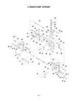
Страница 23: ... 20 LOWER UNIT GROUp ...
Страница 24: ... 21 LOWER UNIT GROUp ...
Страница 25: ...GEAR CASE GROUp 22 ...
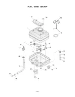
Страница 26: ... 23 FUEL TANK GROUp ...
Страница 27: ... 24 IV TROUBLESHOOTING ...
Страница 28: ... 25 V CROSS SECTION OF MOTOR ...