background image

Digital Controller SIO Driver   

GP-Pro EX Device/PLC Connection Manual

26

‹

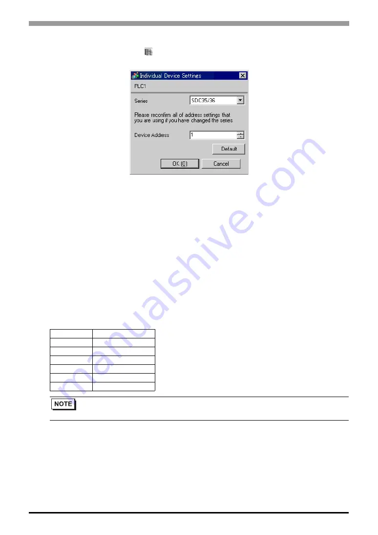
Device Setting

To display the setting screen, click 

 ([Setting]) of the External Device you want to set from [Device-Specific 

Settings] of [Device/PLC Settings].

„

Settings of External Device

Use the PARA key, mode key, enter key, down key and up key in front of the Controller for communication 

settings of the External Device. Please refer to the manual of the Controller for more details.

‹

Procedure

1.Press and hold the PARA key in operation display (2 seconds) to move to the bank selection display.

2.Press the enter key in the bank selection display to move to the bank setup display.

3.Press the PARA key several times to display the setup items.

4.Press the enter key to blink the display area of the setting value.

5.Use the down/up keys to select the setting contents.

6.Press the enter key to confirm the change.

7.Press the mode key to move to the operation display.

‹

Setting Value

Setup Items

Setting Value

C64

0

C65

1

C66

1

C67

1

C68

0

C69

0

• Parameters to be set vary depending on the Controller. Please refer to the manual of the Controller 

for more details.

Содержание DCP31 Series

Страница 1: ... Controller SIO Driver 1 System Configuration 3 2 Selection of External Device 8 3 Example of Communication Setting 9 4 Setup Items 65 5 Cable Diagram 70 6 Supported Device 103 7 Device Code and Address Code 114 8 Error Messages 116 ...

Страница 2: ...l Device Select a model series of the External Device to be connected and connection method 2 Selection of External Device page 8 3 Example of Communication Settings This section shows setting examples for communicating between the Display and the External Device 3 Example of Communication Setting page 9 4 Setup Items This section describes communication setup items on the Display Set communicatio...

Страница 3: ...ock on the controller RS422 485 4 wire Setting Example 4 page 15 Cable Diagram 2 page 71 RS422 485 2 wire Setting Example 5 page 17 Cable Diagram 3 page 75 SDC25 26 C25 2 C26 2 Terminal block on the controller RS422 485 2 wire Setting Example 6 page 19 Cable Diagram6 page 96 SDC30 31 C30 040 C30 041 C31 045 C31 446 C31 546 Terminal block on the controller RS422 485 4 wire Setting Example 7 page 21...

Страница 4: ...on the controller RS422 485 4 wire Setting Example 19 page 45 Cable Diagram 2 page 71 RS422 485 2 wire Setting Example 20 page 47 Cable Diagram 3 page 75 DCP32 P32A 2 Terminal block on the controller RS422 485 4wire Setting Example 21 page 49 Cable Diagram 2 page 71 RS422 485 2 wire Setting Example 22 page 51 Cable Diagram 3 page 75 DCP551 DCP551 2 Terminal block on the controller RS232C Setting E...

Страница 5: ...an connect maximum 16 units of External Device Note that maximum 15 units can be connected if DMC10 is included Do not add the termination resistance when the Controller to be connected using 1 n connection includes the following series SDC15 SDC25 26 SDC35 36 DMC10 Display Controller Display Controller n 1 Controller Controller n 1 Display n 1 COM1 COM2 Controller Controller Controller Controller...

Страница 6: ...50A PS 3651A COM1 1 PS 3700A Pentium 4 M PS 3710A COM1 1 COM2 1 COM3 2 COM4 2 It is necessary to set up the SIO type with the Dip switch Please set up as follows according to SIO type to be used COM3 2 COM3 2 PS 3711A COM1 1 COM2 2 COM2 2 COM2 2 Dip switch Setting Description 1 OFF Reserve always OFF 2 OFF SIO type RS 232C 3 OFF 4 OFF Output mode of SD TXD data Always output 5 OFF Terminal resista...

Страница 7: ...sertion to RD RXD None 7 OFF Short circuit of SDA TXA and RDA RXA Does not Exist 8 OFF Short circuit of SDB TXB and RDB RXB Does not Exist 9 OFF RS RTS Auto control mode Disable 10 OFF Dip switch Setting Description 1 OFF Reserve always OFF 2 ON SIO type RS 422 485 3 ON 4 OFF Output mode of SD TXD data Always output 5 OFF Terminal resistance 220Ω insertion to SD TXD None 6 OFF Terminal resistance ...

Страница 8: ...e External Device to be connected Select Yamatake Corporation Driver Select a model series of the External Device to be connected and connection method Select Digital Controller SIO Check the External Device which can be connected in Digital Controller SIO in system configuration 1 System Configuration page 3 Use System Area Cannot use in this driver Port Select the Display port to be connected to...

Страница 9: ...ation settings of the Display and the External Device recommended by Digital Electronics Corp are shown 3 1 Setting Example 1 Setting of GP Pro EX Communication Settings To display the setting screen select Device PLC Settings from System setting window in workspace When using SDC10 you need to set Wait To Send to 70ms or more ...

Страница 10: ... Press and hold the PARA key in operation mode 3 seconds to move to the parameter mode 2 Press and hold the PARA key in parameter mode 3 seconds to move to the setup mode 3 Press the PARA key several times to display the setup items 4 Use the down up keys to select the setting contents Setting value will blink 5 When you stop operating for 2 seconds blinking of the setting value ends to confirm th...

Страница 11: ...er SIO Driver GP Pro EX Device PLC Connection Manual 11 3 2 Setting Example 2 Setting of GP Pro EX Communication Settings To display the setting screen select Device PLC Settings from System setting window in workspace ...

Страница 12: ...PARA key in operation display 2 seconds to move to the parameter setting display 2 Press and hold the PARA key in the parameter setting display 2 seconds to move to the setup display 3 Press the PARA key several times to display the setup items 4 Use the down up keys to select the setting contents Setting value will blink 5 When you stop key operation for 2 seconds blinking of the setting value en...

Страница 13: ...er SIO Driver GP Pro EX Device PLC Connection Manual 13 3 3 Setting Example 3 Setting of GP Pro EX Communication Settings To display the setting screen select Device PLC Settings from System setting window in workspace ...

Страница 14: ...xternal Device Please refer to the manual of the Controller for more details Procedure 1 Press and hold the ENT key and the down key together 3 seconds or more to display the setup items 2 Press the down up keys to select the setup items and press the ENT key 3 Use the down up keys to select the setup contents and press the ENT key 4 Press the DISP key to move to the standard display Setting Value...

Страница 15: ...er SIO Driver GP Pro EX Device PLC Connection Manual 15 3 4 Setting Example 4 Setting of GP Pro EX Communication Settings To display the setting screen select Device PLC Settings from System setting window in workspace ...

Страница 16: ...xternal Device Please refer to the manual of the Controller for more details Procedure 1 Press and hold the ENT key and the down key together 3 seconds or more to display the setup items 2 Press the down up keys to select the setup items and press the ENT key 3 Use the down up keys to select the setup contents and press the ENT key 4 Press the DISP key to move to the standard display Setting Value...

Страница 17: ...er SIO Driver GP Pro EX Device PLC Connection Manual 17 3 5 Setting Example 5 Setting of GP Pro EX Communication Settings To display the setting screen select Device PLC Settings from System setting window in workspace ...

Страница 18: ...xternal Device Please refer to the manual of the Controller for more details Procedure 1 Press and hold the ENT key and the down key together 3 seconds or more to display the setup items 2 Press the down up keys to select the setup items and press the ENT key 3 Use the down up keys to select the setup contents and press the ENT key 4 Press the DISP key to move to the standard display Setting Value...

Страница 19: ...er SIO Driver GP Pro EX Device PLC Connection Manual 19 3 6 Setting Example 6 Setting of GP Pro EX Communication Settings To display the setting screen select Device PLC Settings from System setting window in workspace ...

Страница 20: ... Press and hold the PARA key in operation display 2 seconds to move to the bank selection display 2 Press the enter key in the bank selection display to move to the bank setup display 3 Press the PARA key several times to display the setup items 4 Press the enter key to blink the display area of the setting value 5 Use the down up keys to select the setting contents 6 Press the enter key to confir...

Страница 21: ...er SIO Driver GP Pro EX Device PLC Connection Manual 21 3 7 Setting Example 7 Setting of GP Pro EX Communication Settings To display the setting screen select Device PLC Settings from System setting window in workspace ...

Страница 22: ...ode before setting Please refer to the manual of the Controller for more details Procedure 1 Press the MODE key twice in the standard display When the RUN READY mode switch display appears change to the READY mode 2 Press and hold the ENT key and the down key together 3 seconds or more to display the setup items 3 Press the down up keys to select the setup items and press the ENT key 4 Use the dow...

Страница 23: ...er SIO Driver GP Pro EX Device PLC Connection Manual 23 3 8 Setting Example 8 Setting of GP Pro EX Communication Settings To display the setting screen select Device PLC Settings from System setting window in workspace ...

Страница 24: ...ode before setting Please refer to the manual of the Controller for more details Procedure 1 Press the MODE key twice in the standard display When the RUN READY mode switch display appears change to the READY mode 2 Press and hold the ENT key and the down key together 3 seconds or more to display the setup items 3 Press the down up keys to select the setup items and press the ENT key 4 Use the dow...

Страница 25: ...er SIO Driver GP Pro EX Device PLC Connection Manual 25 3 9 Setting Example 9 Setting of GP Pro EX Communication Settings To display the setting screen select Device PLC Settings from System setting window in workspace ...

Страница 26: ... Press and hold the PARA key in operation display 2 seconds to move to the bank selection display 2 Press the enter key in the bank selection display to move to the bank setup display 3 Press the PARA key several times to display the setup items 4 Press the enter key to blink the display area of the setting value 5 Use the down up keys to select the setting contents 6 Press the enter key to confir...

Страница 27: ...r SIO Driver GP Pro EX Device PLC Connection Manual 27 3 10 Setting Example 10 Setting of GP Pro EX Communication Settings To display the setting screen select Device PLC Settings from System setting window in workspace ...

Страница 28: ...setting Please refer to the manual of the Controller for more details Procedure 1 Press the PARA key in the standard display to display PARA Next press the ENT key to display rnry and move to the READY mode 2 Press the PARA key several times in the standard display to display SETUP 3 Press the ENT key to display the setup items 4 Press the down up keys to select the setup items and press the ENT k...

Страница 29: ...r SIO Driver GP Pro EX Device PLC Connection Manual 29 3 11 Setting Example 11 Setting of GP Pro EX Communication Settings To display the setting screen select Device PLC Settings from System setting window in workspace ...

Страница 30: ...setting Please refer to the manual of the Controller for more details Procedure 1 Press the PARA key in the standard display to display PARA Next press the ENT key to display rnry and move to the READY mode 2 Press the PARA key several times in the standard display to display SETUP 3 Press the ENT key to display the setup items 4 Press the down up keys to select the setup items and press the ENT k...

Страница 31: ...r SIO Driver GP Pro EX Device PLC Connection Manual 31 3 12 Setting Example 12 Setting of GP Pro EX Communication Settings To display the setting screen select Device PLC Settings from System setting window in workspace ...

Страница 32: ...setting Please refer to the manual of the Controller for more details Procedure 1 Press the PARA key in the standard display to display PARA Next press the ENT key to display rnry and move to the READY mode 2 Press the PARA key several times in the standard display to display SETUP 3 Press the ENT key to display the setup items 4 Press the down up keys to select the setup items and press the ENT k...

Страница 33: ...r SIO Driver GP Pro EX Device PLC Connection Manual 33 3 13 Setting Example 13 Setting of GP Pro EX Communication Settings To display the setting screen select Device PLC Settings from System setting window in workspace ...

Страница 34: ...al Device Please refer to the manual of the Controller for more details Procedure 1 Press the PARA key in the standard display to move to the setup mode 2 Press the ENT key to display the setup items 3 Press the down up keys to select the setup items and press the ENT key 4 Use the down up keys to select the setup contents and press the ENT key 5 Press the DISP key to move to the standard display ...

Страница 35: ...r SIO Driver GP Pro EX Device PLC Connection Manual 35 3 14 Setting Example 14 Setting of GP Pro EX Communication Settings To display the setting screen select Device PLC Settings from System setting window in workspace ...

Страница 36: ...al Device Please refer to the manual of the Controller for more details Procedure 1 Press the PARA key in the standard display to move to the setup mode 2 Press the ENT key to display the setup items 3 Press the down up keys to select the setup items and press the ENT key 4 Use the down up keys to select the setup contents and press the ENT key 5 Press the DISP key to move to the standard display ...

Страница 37: ...r SIO Driver GP Pro EX Device PLC Connection Manual 37 3 15 Setting Example 15 Setting of GP Pro EX Communication Settings To display the setting screen select Device PLC Settings from System setting window in workspace ...

Страница 38: ...al Device Please refer to the manual of the Controller for more details Procedure 1 Press the PARA key in the standard display to move to the setup mode 2 Press the ENT key to display the setup items 3 Press the down up keys to select the setup items and press the ENT key 4 Use the down up keys to select the setup contents and press the ENT key 5 Press the DISP key to move to the standard display ...

Страница 39: ...r SIO Driver GP Pro EX Device PLC Connection Manual 39 3 16 Setting Example 16 Setting of GP Pro EX Communication Settings To display the setting screen select Device PLC Settings from System setting window in workspace ...

Страница 40: ...ting Please refer to the manual of the Controller for more details Procedure 1 Press the PARA key in the standard display to display PARA Next press the ENT key to display rnry and move to the READY mode 2 Press the PARA key several times in the standard display to display SETUP 3 Press the ENT key to display the setup items 4 Press the down up keys to select the setup items and press the ENT key ...

Страница 41: ...r SIO Driver GP Pro EX Device PLC Connection Manual 41 3 17 Setting Example 17 Setting of GP Pro EX Communication Settings To display the setting screen select Device PLC Settings from System setting window in workspace ...

Страница 42: ...ting Please refer to the manual of the Controller for more details Procedure 1 Press the PARA key in the standard display to display PARA Next press the ENT key to display rnry and move to the READY mode 2 Press the PARA key several times in the standard display to display SETUP 3 Press the ENT key to display the setup items 4 Press the down up keys to select the setup items and press the ENT key ...

Страница 43: ...r SIO Driver GP Pro EX Device PLC Connection Manual 43 3 18 Setting Example 18 Setting of GP Pro EX Communication Settings To display the setting screen select Device PLC Settings from System setting window in workspace ...

Страница 44: ...f the Controller After setting turn ON the power of the External Device again 2 Click Set with the ladder software to display the setting screen 3 Click Model Setting from the menu to select the model No of the External Device 4 Click Environmental Setting from the menu to perform the setup transfer setting 5 Select Communication from Basic Function in the tree view to set the communication 6 Tran...

Страница 45: ...r SIO Driver GP Pro EX Device PLC Connection Manual 45 3 19 Setting Example 19 Setting of GP Pro EX Communication Settings To display the setting screen select Device PLC Settings from System setting window in workspace ...

Страница 46: ... Controller for more details Procedure 1 While pressing the FUNC key press the PARA key to move to the screen of the setting group selection 2 Press the PARA key several times to display the setup data setting group and press the ENT key 3 Press the down up keys several times to select the setup items and press the ENT key 4 Use the down up keys to select the setup contents and press the ENT key 5...

Страница 47: ...r SIO Driver GP Pro EX Device PLC Connection Manual 47 3 20 Setting Example 20 Setting of GP Pro EX Communication Settings To display the setting screen select Device PLC Settings from System setting window in workspace ...

Страница 48: ... Controller for more details Procedure 1 While pressing the FUNC key press the PARA key to move to the screen of the setting group selection 2 Press the PARA key several times to display the setup data setting group and press the ENT key 3 Press the down up keys several times to select the setup items and press the ENT key 4 Use the down up keys to select the setup contents and press the ENT key 5...

Страница 49: ...r SIO Driver GP Pro EX Device PLC Connection Manual 49 3 21 Setting Example 21 Setting of GP Pro EX Communication Settings To display the setting screen select Device PLC Settings from System setting window in workspace ...

Страница 50: ... Controller for more details Procedure 1 While pressing the FUNC key press the PARA key to move to the screen of the setting group selection 2 Press the PARA key several times to display the setup data setting group and press the ENT key 3 Press the down up keys several times to select the setup items and press the ENT key 4 Use the down up keys to select the setup contents and press the ENT key 5...

Страница 51: ...r SIO Driver GP Pro EX Device PLC Connection Manual 51 3 22 Setting Example 22 Setting of GP Pro EX Communication Settings To display the setting screen select Device PLC Settings from System setting window in workspace ...

Страница 52: ... Controller for more details Procedure 1 While pressing the FUNC key press the PARA key to move to the screen of the setting group selection 2 Press the PARA key several times to display the setup data setting group and press the ENT key 3 Press the down up keys several times to select the setup items and press the ENT key 4 Use the down up keys to select the setup contents and press the ENT key 5...

Страница 53: ...r SIO Driver GP Pro EX Device PLC Connection Manual 53 3 23 Setting Example 23 Setting of GP Pro EX Communication Settings To display the setting screen select Device PLC Settings from System setting window in workspace ...

Страница 54: ... External Device to the READY mode before setting Please refer to the manual of the Controller for more details Procedure 1 Press the RUN HOLD key while pressing the PROG key to move to the READY mode 2 Press the SETUP key in the standard display to move to the setup mode 3 Press the down up keys several times to select the setup items and press the ENT key 4 Use the down up keys to select the set...

Страница 55: ...r SIO Driver GP Pro EX Device PLC Connection Manual 55 3 24 Setting Example 24 Setting of GP Pro EX Communication Settings To display the setting screen select Device PLC Settings from System setting window in workspace ...

Страница 56: ... External Device to the READY mode before setting Please refer to the manual of the Controller for more details Procedure 1 Press the RUN HOLD key while pressing the PROG key to move to the READY mode 2 Press the SETUP key in the standard display to move to the setup mode 3 Press the down up keys several times to select the setup items and press the ENT key 4 Use the down up keys to select the set...

Страница 57: ...r SIO Driver GP Pro EX Device PLC Connection Manual 57 3 25 Setting Example 25 Setting of GP Pro EX Communication Settings To display the setting screen select Device PLC Settings from System setting window in workspace ...

Страница 58: ... External Device to the READY mode before setting Please refer to the manual of the Controller for more details Procedure 1 Press the RUN HOLD key while pressing the PROG key to move to the READY mode 2 Press the SETUP key in the standard display to move to the setup mode 3 Press the down up keys several times to select the setup items and press the ENT key 4 Use the down up keys to select the set...

Страница 59: ...r SIO Driver GP Pro EX Device PLC Connection Manual 59 3 26 Setting Example 26 Setting of GP Pro EX Communication Settings To display the setting screen select Device PLC Settings from System setting window in workspace ...

Страница 60: ... External Device to the READY mode before setting Please refer to the manual of the Controller for more details Procedure 1 Press the RUN HOLD key while pressing the PROG key to move to the READY mode 2 Press the SETUP key in the standard display to move to the setup mode 3 Press the down up keys several times to select the setup items and press the ENT key 4 Use the down up keys to select the set...

Страница 61: ...r SIO Driver GP Pro EX Device PLC Connection Manual 61 3 27 Setting Example 27 Setting of GP Pro EX Communication Settings To display the setting screen select Device PLC Settings from System setting window in workspace ...

Страница 62: ... External Device to the READY mode before setting Please refer to the manual of the Controller for more details Procedure 1 Press the RUN HOLD key while pressing the PROG key to move to the READY mode 2 Press the SETUP key in the standard display to move to the setup mode 3 Press the down up keys several times to select the setup items and press the ENT key 4 Use the down up keys to select the set...

Страница 63: ...r SIO Driver GP Pro EX Device PLC Connection Manual 63 3 28 Setting Example 28 Setting of GP Pro EX Communication Settings To display the setting screen select Device PLC Settings from System setting window in workspace ...

Страница 64: ... External Device to the READY mode before setting Please refer to the manual of the Controller for more details Procedure 1 Press the RUN HOLD key while pressing the PROG key to move to the READY mode 2 Press the SETUP key in the standard display to move to the setup mode 3 Press the down up keys several times to select the setup items and press the ENT key 4 Use the down up keys to select the set...

Страница 65: ...ect Device PLC Settings from System setting window in workspace Setup Items Setup Description SIO Type Select the SIO type to communicate with the External Device Speed Select speed between the External Device and the Display Data Length Select data length Parity Select how to check parity Stop Bit Select stop bit length Flow Control Display the communication control method to prevent overflow of ...

Страница 66: ...xternal Device use an integer from 0 to 255 to enter how many times the Display retransmits the command Wait To Send Use an integer from 0 to 255 to enter standby time ms for the Display from receiving packets to transmitting next commands RI VCC Switches RI VCC of the 9th pin It is necessary to change RI 5V by changeover switch of IPC when connect with IPC Please refer to the manual of the IPC fo...

Страница 67: ... the serial interface specifications of Display unit for SIO Type We cannot guarantee the operation if a communication type that the serial interface does not support is specified For details concerning the serial interface specifications refer to the manual for Display unit Speed Select speed between the External Device and the Display Data Length Select data length Parity Select how to check par...

Страница 68: ... Equipment Settings Touch the External Device you want to set from the displayed list and touch Option Wait To Send Use an integer from 0 to 255 to enter standby time ms for the Display from receiving packets to transmitting next commands Setup Items Setup Description Device PLC Name Select the External Device to set Device name is a title of the External Device set with GP Pro EX Initial value PL...

Страница 69: ...EX Device PLC Connection Manual 69 Setup Items Setup Description RI VCC Switches RI VCC of the 9th pin It is necessary to change RI 5V by changeover switch of IPC when connect with IPC Please refer to the manual of the IPC for more detail ...

Страница 70: ...p Check the terminal No on the side of External Device in the manual of the External Device It varies depending on the additional function Connect the isolation unit when communication is not stabilized under the influence of a noise etc Recommended cable Cable Diagram 1 Company Name Model No Fujikura Densen 2 cores IPEV S 0 9mm2x1P 3 cores ITEV S 0 9mm2 x1T Hitachi Densen 2 cores KPEV S 0 9mm2x1P...

Страница 71: ...cate by RS 422 485 4 wire can be used COM Port of IPC page 6 A COM port conversion adapter by Pro face CA3 ADPCOM 01 Terminal block conversion adapter by Pro face CA3 ADPTRM 01 Your own cable Cable length 500m or less B Your own cable GP 4 COM2 4 All GP models except GP 3200 series and AGP 3302B C Online adapter by Pro face CA4 ADPONL 01 Terminal block conversion adapter by Pro face CA3 ADPTRM 01 ...

Страница 72: ...l resistance Controller Your own cable Signal name RDB SDB SG TERM CA3 ADPCOM 01 CA3 ADPTRM 01 Display Shield Terminal block RDA SDA RDB SDB SG FG RDA SDA RDB SDB SG FG RDA SDA 150 ǡ more than 1 2W r5 Terminal resistance 150 ǡ more than 1 2W r5 Terminal resistance Signal name Terminal block Signal name 150 ǡ more than 1 2W r5 Terminal resistance 150 ǡ more than 1 2W r5 Terminal resistance Shield C...

Страница 73: ...more than 1 2W r5 Terminal resistance Controller Controller Display Signal name RDB SDB SG TERM CA4 ADPONL 01 CA3 ADPTRM 01 Display Shield Terminal block RDA SDA Signal name RDB SDB SG FG RDA SDA 150 ǡ more than 1 2W r5 Terminal resistance 150 ǡ more than 1 2W r5 Terminal resistance Controller 150 ǡ more than 1 2W r5 Terminal resistance 150 ǡ more than 1 2W r5 Terminal resistance Your own cable Si...

Страница 74: ...1 2W r5 Terminal resistance Terminal block Controller 150 ǡ more than 1 2W r5 Terminal resistance 150 ǡ more than 1 2W r5 Terminal resistance Your own cable CA4 ADPONL 01 Display Signal name RDB 7 RDA 2 SDB 8 9 TERMTX SDA FG 3 TERMRX 1 SG 5 D Sub 9 Pin plug Pin Shell Shield Signal name RDB SDB SG FG RDA SDA Shield Signal name RDB SDB SG FG RDA SDA 150 ǡ more than 1 2W r5 Terminal resistance 150 ǡ ...

Страница 75: ...our own cable Cable length 500m or less B Your own cable GP 3 COM2 3 All GP models except GP 3200 series and AGP 3302B C Online adapter by Pro face CA4 ADPONL 01 Terminal block conversion adapter by Pro face CA3 ADPTRM 01 Your own cable D Online adapter by Pro face CA4 ADPONL 01 Your own cable IPC 4 4 Only the COM port which can communicate by RS 422 485 2 wire can be used COM Port of IPC page 6 E...

Страница 76: ... 01 Display Shield RDA SDA Signal name RDB SDB SG FG RDA SDA 150 ǡ more than 1 2W r5 Terminal resistance Terminal block Controller 150 ǡ more than 1 2W r5 Terminal resistance Your own cable Signal name RDB SDB SG TERM CA3 ADPCOM 01 CA3 ADPTRM 01 Display Shield RDA SDA Signal name RDB SDB SG FG RDA SDA Shield Signal name RDB SDB SG FG RDA SDA 150 ǡ more than 1 2W r5 Terminal resistance Terminal blo...

Страница 77: ... FG RDA SDA 150 ǡ more than 1 2W r5 Terminal resistance Terminal block Controller 150 ǡ more than 1 2W r5 Terminal resistance Display Signal name SDA 3 RDB 2 SG 5 4 ERA SDB ERB 7 9 CSB 6 FG RDA 1 CSA 8 D Sub 9 Pin socket Pin Shell Shield Signal name RDB SDB SG FG RDA SDA Shield Signal name RDB SDB SG FG RDA SDA 150 ǡ more than 1 2W r5 Terminal resistance Terminal block Controller Terminal block Co...

Страница 78: ...play Shield RDA SDA Signal name RDB SDB SG FG RDA SDA 150 ǡ more than 1 2W r5 Terminal resistance Terminal block Controller 150 ǡ more than 1 2W r5 Terminal resistance Your own cable Signal name RDB SDB SG TERM CA4 ADPONL 01 CA3 ADPTRM 01 Display Shield RDA SDA Signal name RDB SDB SG FG RDA SDA Shield Signal name RDB SDB SG FG RDA SDA 150 ǡ more than 1 2W r5 Terminal resistance Terminal block Cont...

Страница 79: ...B SG FG RDA SDA 150 ǡ more than 1 2W r5 Terminal resistance Terminal block Signal name Controller 150 ǡ more than 1 2W r5 Terminal resistance Your own cable CA4 ADPONL 01 Display RDB 7 RDA 2 SDB 8 9 TERMTX SDA FG 3 TERMRX 1 SG 5 Shell Shield RDB SDB SG FG RDA SDA Shield RDB SDB SG FG RDA SDA 150 ǡ more than 1 2W r5 Terminal resistance Signal name D Sub 9 Pin plug Pin Terminal block Signal name Con...

Страница 80: ...ck Controller more than 1 2W Terminal resistance Your own cable 150ǡr5 Signal name RDB SDB SG TERM CA3 ADPCOM 01 CA3 ADPTRM 01 Display Shield RDA SDA Signal name RDB SDB SG FG RDA SDA 150ǡr5 more than 1 2W Terminal resistance Terminal block Controller more than 1 2W Terminal resistance Your own cable 150ǡr5 Signal name RDB SDB SG TERM CA3 ADPCOM 01 CA3 ADPTRM 01 Display Shield RDA SDA Signal name ...

Страница 81: ...B SG FG RDA SDA 150ǡr5 more than 1 2W Terminal resistance Terminal block Controller 150ǡr5 more than 1 2W Terminal resistance Display Signal name NC 3 DATA 2 GND 㧔SG㧕 5 NC 7 ERA 4 CSA 8 ERB 9 CSB 6 FG DATA 1 D Sub 9 Pin socket Pin Shell Shield Signal name RDB SDB SG FG RDA SDA Shield Signal name RDB SDB SG FG RDA SDA 150ǡr5 more than 1 2W Terminal resistance Terminal block Controller Terminal bloc...

Страница 82: ...ur own cable Cable length 500m or less B Your own cable GP 3 COM2 3 All GP models except GP 3200 series and AGP 3302B C Online adapter by Pro face CA4 ADPONL 01 Terminal block conversion adapter by Pro face CA3 ADPTRM 01 Your own cable D Online adapter by Pro face CA4 ADPONL 01 Your own cable IPC 4 4 Only the COM port which can communicate by RS 422 485 2 wire can be used COM Port of IPC page 6 E ...

Страница 83: ...1 n Connection Termination resistance is not necessary Termination resistance is not necessary Signal name RDB SDB SG TERM CA3 ADPCOM 01 CA3 ADPTRM 01 Display Shield RDA SDA DA DB SG Terminal block Signal name Controller Your own cable Signal name RDB SDB SG TERM CA3 ADPCOM 01 CA3 ADPTRM 01 Display Shield RDA SDA DA DB SG Shield DA DB SG Terminal block Signal name Controller Terminal block Signal ...

Страница 84: ...ance is not necessary Signal name SDA 3 RDB 2 SG 5 4 ERA SDB ERB 7 9 CSB 6 FG RDA 1 CSA 8 D Sub 9 Pin socket Pin Shell Shield DA DB SG Terminal block Signal name Controller Display SDA 3 RDB 2 SG 5 4 ERA SDB ERB 7 9 CSB 6 FG RDA 1 CSA 8 D Sub 9 Pin socket Shell Shield DA DB SG Shield DA DB SG Signalname Pin Terminal block Signal name Controller Terminal block Signal name Controller Display ...

Страница 85: ...nnection Termination resistance is not necessary Termination resistance is not necessary Signal name RDB SDB SG TERM CA4 ADPONL 01 CA3 ADPTRM 01 Display Shield RDA SDA DA DB SG Terminal block Signal name Controller Your own cable Signal name RDB SDB SG TERM CA4 ADPONL 01 CA3 ADPTRM 01 Display Shield RDA SDA DA DB SG Shield DA DB SG Terminal block Signal name Controller Terminal block Signal name C...

Страница 86: ...stance is not necessary CA4 ADPONL 01 Display RDB 7 RDA 2 SDB 8 9 TERMTX SDA FG 3 TERMRX 1 SG 5 D Sub 9 Pin plug Shell Shield DA DB SG Signal name Pin Terminal block Signal name Controller Your own cable CA4 ADPONL 01 Display RDB 7 RDA 2 SDB 8 9 TERMTX SDA FG 3 TERMRX 1 SG 5 Shell Shield DA DB SG Shield DA DB SG Signal name D Sub 9 Pin plug Pin Terminal block Signal name Controller Terminal block ...

Страница 87: ...1 n Connection Termination resistance is not necessary Termination resistance is not necessary Signal name RDB SDB SG TERM CA3 ADPCOM 01 CA3 ADPTRM 01 Display Shield RDA SDA DA DB SG Terminal block Signal name Controller Your own cable Signal name RDB SDB SG TERM CA3 ADPCOM 01 CA3 ADPTRM 01 Display Shield RDA SDA DA DB SG Shield DA DB SG Terminal block Signal name Controller Terminal block Signal ...

Страница 88: ...s not necessary Signal name NC 3 DATA 2 GND 㧔SG㧕 5 NC 7 ERA 4 CSA 8 FG DATA 1 D Sub 9 Pin socket Pin Shell Shield DA DB SG Terminal block Signal name Controller Display ERB 9 CSB 6 NC 3 DATA 2 GND 㧔SG㧕 5 NC 7 ERA 4 CSA 8 ERB 9 CSB 6 FG DATA 1 D Sub 9 Pin socket Shell Shield DA DB SG Shield DA DB SG Signalname Pin Terminal block Signal name Controller Terminal block Signal name Controller Display ...

Страница 89: ...ur own cable Cable length 500m or less B Your own cable GP 3 COM2 3 All GP models except GP 3200 series and AGP 3302B C Online adapter by Pro face CA4 ADPONL 01 Terminal block conversion adapter by Pro face CA3 ADPTRM 01 Your own cable D Online adapter by Pro face CA4 ADPONL 01 Your own cable IPC 4 4 Only the COM port which can communicate by RS 422 485 2 wire can be used COM Port of IPC page 6 E ...

Страница 90: ... ADPCOM 01 CA3 ADPTRM 01 Display Shield RDA SDA 㧗 㧙 SG FG 150 ǡ more than 1 2W r5 Terminal resistance 150 ǡ more than 1 2W r5 Terminal resistance Terminal block Signal name Controller Your own cable Signal name RDB SDB SG TERM CA3 ADPCOM 01 CA3 ADPTRM 01 Display Shield RDA SDA 㧗 㧙 SG FG Shield 㧗 㧙 SG FG 150 ǡ more than 1 2W Terminal resistance Terminal block Signal name Controller Terminal block S...

Страница 91: ...Shell Terminal block Signal name Controller 150 ǡ more than 1 2W r5 Terminal resistance 150 ǡ more than 1 2W r5 Terminal resistance Display SDA 3 RDB 2 SG 5 4 ERA SDB ERB 7 9 CSB 6 FG RDA 1 CSA 8 Shield 㧗 㧙 SG FG Shield 㧗 㧙 SG FG Signal name D Sub 9 Pin socket Pin Shell 150 ǡ more than 1 2W r5 Terminal resistance Terminal block Signal name Controller Terminal block Signal name Controller 150 ǡ mor...

Страница 92: ... CA3 ADPTRM 01 Display Shield RDA SDA 㧗 㧙 SG FG 150 ǡ more than 1 2W r5 Terminal resistance Terminal block Signal name Controller 150 ǡ more than 1 2W r5 Terminal resistance Your own cable Signal name RDB SDB SG TERM CA4 ADPONL 01 CA3 ADPTRM 01 Display Shield RDA SDA 㧗 㧙 SG FG Shield 㧗 㧙 SG FG 150 ǡ more than 1 2W r5 Terminal resistance Terminal block Signal name Controller Terminal block Signal n...

Страница 93: ... 2W r5 Terminal resistance Signal name D Sub 9 Pin plug Pin Shell Terminal block Signal name 150 ǡ more than 1 2W r5 Terminal resistance Controller Your own cable CA4 ADPONL 01 Display RDB 7 RDA 2 SDB 8 9 TERMTX SDA FG 3 TERMRX 1 SG 5 Shield 㧗 㧙 SG FG Shield 㧗 㧙 SG FG Signal name D Sub 9 Pin plug Pin Shell Terminal block Signal name Controller Terminal block Signal name Controller 150 ǡ more than ...

Страница 94: ...3 ADPCOM 01 CA3 ADPTRM 01 Display Shield RDA SDA SG FG 150ǡr5 more than 1 2W Terminal resistance 150ǡr5 more than 1 2W Terminal resistance Terminal block Signal name Controller Your own cable 㧗 㧙 Signal name RDB SDB SG TERM CA3 ADPCOM 01 CA3 ADPTRM 01 Display Shield RDA SDA SG FG Shield SG FG 150ǡr5 more than 1 2W Terminal resistance Terminal block Signal name Controller Terminal block Signal name...

Страница 95: ...Shell Terminal block Signal name Controller 150ǡr5 more than 1 2W Terminal resistance 150ǡr5 more than 1 2W Terminal resistance Display 㧗 㧙 NC 3 DATA 2 GND 㧔SG㧕 5 NC 7 ERA 4 CSA 8 FG DATA 1 Shield SG FG Shield SG FG Signal name D Sub 9 Pin socket Pin Shell 150ǡr5 more than 1 2W Terminal resistance Terminal block Signal name Controller Terminal block Signal name Controller 150ǡr5 more than 1 2W Ter...

Страница 96: ...ur own cable Cable length 500m or less B Your own cable GP 3 COM2 3 All GP models except GP 3200 series and AGP 3302B C Online adapter by Pro face CA4 ADPONL 01 Terminal block conversion adapter by Pro face CA3 ADPTRM 01 Your own cable D Online adapter by Pro face CA4 ADPONL 01 Your own cable IPC 4 4 Only the COM port which can communicate by RS 422 485 2 wire can be used COM Port of IPC page 6 E ...

Страница 97: ...Connection Termination resistance is not necessary Termination resistance is not necessary Signal name RDB SDB SG TERM CA3 ADPCOM 01 CA3 ADPTRM 01 Display Shield RDA SDA DA DB SG FG Terminal block Signal name Controller Your own cable Signal name RDB SDB SG TERM CA3 ADPCOM 01 CA3 ADPTRM 01 Display Shield RDA SDA DA DB SG FG Shield DA DB SG FG Terminal block Signal name Controller Terminal block Si...

Страница 98: ...is not necessary SDA 3 RDB 2 SG 5 4 ERA SDB ERB 7 9 CSB 6 FG RDA 1 CSA 8 Shield DA DB SG FG Signal name D Sub 9 Pin socket Pin Shell Terminal block Signal name Controller Display SDA 3 RDB 2 SG 5 4 ERA SDB ERB 7 9 CSB 6 FG RDA 1 CSA 8 Shield DA DB SG FG Shield DA DB SG FG Signal name D Sub 9 Pin socket Pin Shell Terminal block Signal name Controller Terminal block Signal name Controller Display ...

Страница 99: ...ion Termination resistance is not necessary Termination resistance is not necessary Signal name RDB SDB SG TERM CA4 ADPONL 01 CA3 ADPTRM 01 Display Shield RDA SDA DA DB SG FG Terminal block Signal name Controller Your own cable Signal name RDB SDB SG TERM CA4 ADPONL 01 CA3 ADPTRM 01 Display Shield RDA SDA DA DB SG FG Shield DA DB SG FG Terminal block Signal name Controller Terminal block Signal na...

Страница 100: ...ce is not necessary CA4 ADPONL 01 Display RDB 7 RDA 2 SDB 8 9 TERMTX SDA FG 3 TERMRX 1 SG 5 Shield DA DB SG FG Signal name D Sub 9 Pin plug Pin Shell Terminal block Signal name Controller Your own cable CA4 ADPONL 01 Display RDB 7 RDA 2 SDB 8 9 TERMTX SDA FG 3 TERMRX 1 SG 5 Shield DA DB SG FG Shield DA DB SG FG Signal name D Sub 9 Pin plug Pin Shell Terminal block Signal name Controller Terminal b...

Страница 101: ...Connection Termination resistance is not necessary Termination resistance is not necessary Signal name RDB SDB SG TERM CA3 ADPCOM 01 CA3 ADPTRM 01 Display Shield RDA SDA DA DB SG FG Terminal block Signal name Controller Your own cable Signal name RDB SDB SG TERM CA3 ADPCOM 01 CA3 ADPTRM 01 Display Shield RDA SDA DA DB SG FG Shield DA DB SG FG Terminal block Signal name Controller Terminal block Si...

Страница 102: ...ot necessary NC 3 DATA 2 GND 㧔SG㧕 5 NC 7 ERA 4 CSA 8 FG DATA 1 Shield DA DB SG FG Signal name D Sub 9 Pin socket Pin Shell Terminal block Signal name Controller Display ERB 9 CSB 6 NC 3 DATA 2 GND SG 5 NC 7 ERA 4 CSA 8 FG DATA 1 Shield DA DB SG FG Shield DA DB SG FG Signal name D Sub 9 Pin socket Pin Shell Terminal block Signal name Controller Terminal block Signal name Controller Display ERB 9 CS...

Страница 103: ...External Device first Then it changes the target bit address among the word data once read and returns the word data to the External Device Note that the correct data may not be written if you change the word address value in the ladder program while the Display reads the data of the External Device and returns it to the External Device To set Enable System Data Area in the system area setting of ...

Страница 104: ...alue in the ladder program while the Display reads the data of the External Device and returns it to the External Device To set Enable System Data Area in the system area setting of GP Pro EX may cause malfunction Do not set Enable System Data Area You can set only reading area size for the system data area available to use in the Controller Please refer to the GP Pro EX Reference Manual for readi...

Страница 105: ... ladder program while the Display reads the data of the External Device and returns it to the External Device To set Enable System Data Area in the system area setting of GP Pro EX may cause malfunction Do not set Enable System Data Area You can set only reading area size for the system data area available to use in the Controller Please refer to the GP Pro EX Reference Manual for reading area siz...

Страница 106: ...he ladder program while the Display reads the data of the External Device and returns it to the External Device To set Enable System Data Area in the system area setting of GP Pro EX may cause malfunction Do not set Enable System Data Area You can set only reading area size for the system data area available to use in the Controller Please refer to the GP Pro EX Reference Manual for reading area s...

Страница 107: ...ladder program while the Display reads the data of the External Device and returns it to the External Device To set Enable System Data Area in the system area setting of GP Pro EX may cause malfunction Do not set Enable System Data Area You can set only reading area size for the system data area available to use in the Controller Please refer to the GP Pro EX Reference Manual for reading area size...

Страница 108: ...ladder program while the Display reads the data of the External Device and returns it to the External Device To set Enable System Data Area in the system area setting of GP Pro EX may cause malfunction Do not set Enable System Data Area You can set only reading area size for the system data area available to use in the Controller Please refer to the GP Pro EX Reference Manual for reading area size...

Страница 109: ...ladder program while the Display reads the data of the External Device and returns it to the External Device To set Enable System Data Area in the system area setting of GP Pro EX may cause malfunction Do not set Enable System Data Area You can set only reading area size for the system data area available to use in the Controller Please refer to the GP Pro EX Reference Manual for reading area size...

Страница 110: ...ladder program while the Display reads the data of the External Device and returns it to the External Device To set Enable System Data Area in the system area setting of GP Pro EX may cause malfunction Do not set Enable System Data Area You can set only reading area size for the system data area available to use in the Controller Please refer to the GP Pro EX Reference Manual for reading area size...

Страница 111: ...he ladder program while the Display reads the data of the External Device and returns it to the External Device To set Enable System Data Area in the system area setting of GP Pro EX may cause malfunction Do not set Enable System Data Area You can set only reading area size for the system data area available to use in the Controller Please refer to the GP Pro EX Reference Manual for reading area s...

Страница 112: ... ladder program while the Display reads the data of the External Device and returns it to the External Device To set Enable System Data Area in the system area setting of GP Pro EX may cause malfunction Do not set Enable System Data Area You can set only reading area size for the system data area available to use in the Controller Please refer to the GP Pro EX Reference Manual for reading area siz...

Страница 113: ... ladder program while the Display reads the data of the External Device and returns it to the External Device To set Enable System Data Area in the system area setting of GP Pro EX may cause malfunction Do not set Enable System Data Area You can set only reading area size for the system data area available to use in the Controller Please refer to the GP Pro EX Reference Manual for reading area siz...

Страница 114: ...DC26 SDC35 SDC36 7 3 SDC20 SDC21 7 4 SDC30 SDC31 7 5 SDC40A 7 6 SDC40B Device Device Name Device Code HEX Address Code Data 0080 Word Address Device Device Name Device Code HEX Address Code Data 0080 Word Address Device Device Name Device Code HEX Address Code Data 0080 Word Address Device Device Name Device Code HEX Address Code Data 0080 Word Address Device Device Name Device Code HEX Address Co...

Страница 115: ...vice Name Device Code HEX Address Code Data 0080 Word Address Device Device Name Device Code HEX Address Code Data 0080 Word Address Device Device Name Device Code HEX Address Code Data 0080 Word Address Device Device Name Device Code HEX Address Code Data 0080 Word Address Device Device Name Device Code HEX Address Code Data 0080 Word Address ...

Страница 116: ... of External Device set with GP Pro EX Initial value PLC1 Error Message Displays messages related to the error which occurs Error Occurrence Area Displays IP address or device address of External Device where error occurs or error codes received from External Device IP address is displayed such as IP address Decimal MAC address Hex Device address is displayed such as Address Device addressî Receiv...

Отзывы: