– 17 –
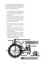
About the front and rear wheel speed sensor
Do not remove the speed sensors installed at
the front and rear wheels because they are
used for regulating YRC controls.
•
If you change the front and rear wheels
to non-standard parts, manufacture and
attach a rotor and sensor referring to the
diagram below.
•
If you change the front fork/rear brake
bracket to a non-standard part too, create
a mount for the sensor assembly and
attach the front and rear wheel sensors
referring to the diagram below.
*1. When manufacturing a rotor and sensor,
use a steel type material with magnetic
properties.
*2. Make the angle of attachment in the
rotation direction of the rotor of the sensor
assembly the same as the angle indicated
in the diagram below.
*3. If you change the rotor sensor or sensor
assembly attachment bracket to a non-
standard part, there is a possibility of
malfunction due to vibration or noise even
if the part is attached properly.
THIRD ANGLE PROJECTION METHOD
Sensor mount
Reference shape
M6×1.0
14±0.1
Φ11.8
+0.1
0
ROTOR, SENSOR
0.8 – 2.3
ROTOR, SENSOR
t2
2CR-85970-00
Center of sensor
D/2±0.2
Rotation
direction
100°
FR. WHEEL SENSOR ASSY.
2CR-85980-00
RR. WHEEL SENSOR ASSY.
(40 parts
equiangularly)
Diameter at sensor
detecting position
ΦD (90 – 180)
40×4±0.05
(when D=Φ90: 4 mm, when D=Φ180: 8 mm)
Holes (40 locations)
40×8±0.2
(4)
Содержание YZF-R1
Страница 1: ......
Страница 43: ...40 36 38 33 29 29 34 21 22 22 24 23 23 35 25 26 37 28 30 32 31 30 28 28 29 27...
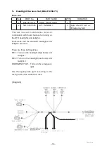
Страница 79: ...76 4 Headlight Cord Wiring Diagram...
Страница 80: ...77 5 YZF R1 Wiring Diagram...
Страница 82: ...Published by YAMAHA MOTOR ENGINEERING co LTD...

