


YST-SW800
YST-SW800
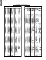
Check the operation and make adjustment as follows.
a. Connect CB205.
b. Connect the probe of the oscilloscope between TP201
and TP202.
c. Turn on the power switch and the STANDBY/ON switch
on the front panel.
d. Check the waveform on the oscilloscope and adjust
VR201 so that a = b is obtained.
Permissible range: a/b = 1.0
±
0.1
CAUTION
Electric potential is always applied to the ground side of the oscilloscope.
Be careful so that no other part comes in contact with it.
Caution for operation check of the SW power supply section and the power amplifier
As a high voltage is applied to the SW power supply section and the power amplifier, be careful not
to receive an electric shock.
V : 50V/div
H : 10
µ
sec/div
AC range
1 : 1 probe
0V
a
b
280Vp-p
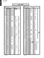
Power (1) P.C.B
Q18
Q16
Q22
Q24
Q39
Q25
Q23
Q17
Q19
– B
GND
+ B
Main (1) P.C.B
Main (2) P.C.B
q
6
Содержание YST-SW800
Страница 3: ...YST SW800 YST SW800 REAR PANEL 2 U C models A model B G models ...
Страница 26: ...YST SW800 YST SW800 ...