background image

11

 En

Placing

PREPARATION

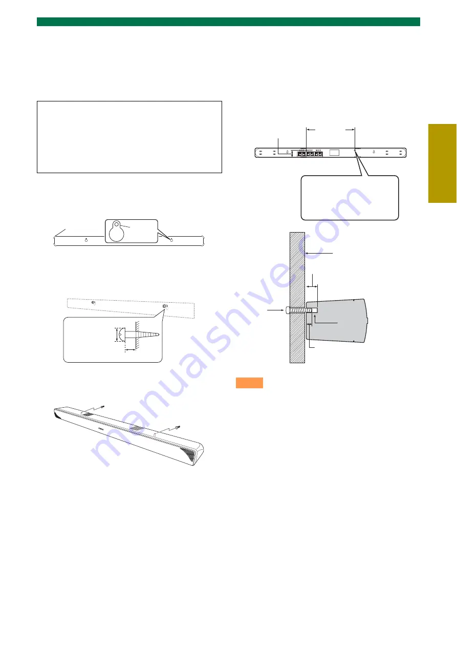
Attaching the speaker to a wall

Installing the speaker using the keyholes

You can attach the speaker to a wall using 
commercially available screws (#8, Diameter: 7 to 9 
mm (1/4” to 3/8”)).

1

Attach the supplied mounting template on 
a wall and mark the holes of the mounting 
template.

2

Remove the mounting template and then 
install the commercially available screws 
at the marks.

3

Hang the speaker on the screws using the 
keyholes on the back of the speaker.

Installing the speaker using the screw 
holes

You can also use the screw holes on the rear of the 
speaker for installing the speaker using a 
commercially available rack etc.

• Attach the speaker to a rack or wall. Do not attach the 

speaker to a wall that is made of weak materials such as 
plaster or veneered woods. Doing so may cause the 
speaker to fall.

• Use commercially available screws that can support the 

weight of the installation.

• Make sure you use specified screws to attach the speaker. 

Using clamps other than specified screws, such as short 
screws, nails, or two-sided tape, may cause the speaker to 
fall.

• When connecting the speaker, fix the speaker cables in 

place where they will not become loose. If your foot or 
hand accidentally gets caught on a loose speaker cable, the 
speaker may fall.

• After attaching the speaker, check that the speaker is fixed 

securely. Yamaha will bear no responsibility for any 
accidents caused by improper installations.

When installing the speaker on a wall, all 
installation work must be performed by a 
qualified contractor or dealer. The customer 
must never attempt to perform this installation 
work. Improper or inadequate installation could 
cause the speaker to fall, resulting in personal 
injury.

Tapes or thumbtacks

Mark

4 to 6 mm (3/16” to 1/4”)

Diameter: 
7 to 9 mm or 
more (#8, 1/4” 
to 3/8” or more)

Notes

Screw holes

Hole depth: 14 mm (9/16”)

Diameter: 6 mm (1/4”)

Pitch: 256 mm (10-1/16”)

256 mm

(10-1/16”)

37 mm (1-7/16”)

Rack etc.

14 mm (9/16”)

Screw
(M6)

Screw 
hole

Min 7 mm (1/4”)

NS-BR300

Содержание YHT-S400

Страница 1: ...Home Theater Package Subwoofer Integrated Receiver Speaker YHT S400 SR 300 NS BR300 Owner s Manual English...

Страница 2: ...or when unused for long periods of time 14 Refer all servicing to qualified service personnel Servicing is required when the apparatus has been damaged in any way such as power supply cord or plug is...

Страница 3: ...e with these requirements provides a reasonable level of assurance that your use of this product in a residential environment will not result in harmful interference with other electronic devices This...

Страница 4: ...om a wall outlet or the unit during a lightning storm 14 Do not attempt to modify or fix this unit Contact qualified Yamaha service personnel when any service is needed The cabinet should never be ope...

Страница 5: ...ound tone control 21 Adjusting the audio delay 21 Setting the audio output 21 Switching on off the HDMI control function 21 Changing the brightness of the front panel display 22 Changing the setting o...

Страница 6: ...erence Guide If the effective operation distance of the remote control decreases considerably replace the batteries with two new ones as soon as possible Do not use an old battery together with new on...

Страница 7: ...the operational status of the system P 14 Rear panel of the subwoofer integrated receiver 1 Power Cable For connecting an AC wall outlet P 12 2 HDMI IN 1 3 HDMI OUT HDMI IN 1 3 for connecting HDMI com...

Страница 8: ...ders of the system is activated 4 DOCK indicator Lights up when the system is receiving a signal from an iPod stationed in the Yamaha iPod universal dock such as YDS 11 sold separately connected to th...

Страница 9: ...trol the wheel of iPod 5 RETURN Returns to the previous menu or cancels preset registration pairing operation 6 SUBWOOFER Adjust the volume balance of subwoofer P 21 7 SURROUND MODE Selects the surrou...

Страница 10: ...ing the location of the subwoofer integrated receiver Depending on your installation environment connections to external components can be done before installing this system We recommend that you temp...

Страница 11: ...ight of the installation Make sure you use specified screws to attach the speaker Using clamps other than specified screws such as short screws nails or two sided tape may cause the speaker to fall Wh...

Страница 12: ...the radio wave reception is weak in your area or you want to improve the radio wave reception we recommend that you use an outdoor antenna For details consult your nearest authorized Yamaha dealer or...

Страница 13: ...a TV from this system you can select optical digital input and connect to digital output jack y For analog connection you need to connect an audio cable to the analog input terminal You can connect e...

Страница 14: ...n off the volume temporarily press MUTE While the mute function is activated the VOLUME indicator flashes To resume the volume press MUTE again or press VOLUME When sound of HDMI is output from the TV...

Страница 15: ...EREO The system memorizes the settings assigned to each input source While watching TV use this function when you feel uncomfortable with the difference in volume between channels TV programs and comm...

Страница 16: ...xisting under a preset number is cleared when you store a new station under the same preset number If the number of received stations does not reach 40 automatic preset tuning automatically stops afte...

Страница 17: ...the frequency appears in the display y You can cancel the operation and return to OPTION menu by pressing RETURN on the remote control 3 Select the preset number of the registered station you want to...

Страница 18: ...iver you can enjoy playback of your iPod Supported iPod iPod Click and Wheel including iPod classic iPod nano iPod mini iPod touch Battery charge feature This system charges the battery of an iPod sta...

Страница 19: ...communication between them The connecting operation on the system is only available for the most recently connected Bluetooth component 1 Press DOCK to set the input to DOCK 2 Press OPTION to enter OP...

Страница 20: ...turn to the previous menu If you do not operate within 30 seconds after entering the setup menu the system automatically exits the setup menu Setup menu Overview Item Description of function Page 1 SW...

Страница 21: ...ange Default setting AUTO AUTO 0 to 240 ms You can adjust the delay time by the 10 ms AUTO If you operate HDMI connection to a TV with the function to automatically adjusting the audio delay you can a...

Страница 22: ...ted front left right center channels such as a bar type speaker 2CH When you connect front left right 2 channel speakers 3CH When you connect front left right 2 channel speakers and a center speaker T...

Страница 23: ...able the HDMI control function on each device For this system set HDMI CONTROL to ON P 21 For external devices refer to the instruction manual supplied with each device 3 Turn off the TV and then turn...

Страница 24: ...s set to TV Set HDMI AUDIO in the setup menu to AMP 21 Sound is too low on one side The cables may be connected improperly Make sure all cables are connected properly 12 Speaker channels other than th...

Страница 25: ...0 ms 21 The HDMI control function does not operate properly The number of the connected HDMI components is over the limit Disconnect some of the HDMI components No picture or sound The connected HDMI...

Страница 26: ...dio receiver such as YBA 10 sold separately and the Bluetooth component are in the process of the pairing The Yamaha Bluetooth wireless audio receiver such as YBA 10 sold separately and the Bluetooth...

Страница 27: ...th allows HDTVs and other displays go from millions of colors to billions of colors and eliminate on screen color banding for smooth tonal transitions and subtle gradations between colors The increase...

Страница 28: ...ansmits all ATSC HDTV standards and supports 8 channel digital audio with bandwidth to spare to accommodate future enhancements and requirements When used in combination with HDCP High bandwidth Digit...

Страница 29: ...NS BR300 Type Accoustic suspension type Non magnetic shielding type Driver Full range 4 10 cm 1 1 2 4 in cone 3 Frequency Response 150 Hz to 20 kHz Impedance 6 Dimensions W H D NS BR300 800 50 70 mm...

Страница 30: ...appropriately so that the component outputs the bitstream audio signals directly does not decode the bitstream signals on the component Refer to the supplied instruction manuals for details Video sig...

Страница 31: ...YC173A0 OMEN1...

Отзывы: