PERIODIC MAINTENANCE
– 24 –
EAS32024
CHECKING THE VEHICLE USING THE
YAMAHA DIAGNOSTIC TOOL
Use the Yamaha diagnostic tool and check the
vehicle according to the following procedure.
1. Remove:
• Seat
Refer to “GENERAL CHASSIS (1)” in chapter
4. (Manual No.: B34-F8197-E2)
2. Remove the protective cap “1”, and then con-
nect the Yamaha diagnostic tool to the cou-
pler.
3. Check:
• Fault codes (fuel injection system and ABS)
TIP
Use the “Diagnosis of malfunction” function of
the Yamaha diagnostic tool to check the fault
codes. For information about using the Yamaha
diagnostic tool, refer to the operation manual
that is included with the tool.
Fault code number is displayed
→
Check and
repair the probable cause of the malfunction.
Refer to “TROUBLESHOOTING DETAILS
(FAULT CODE)” on page 63 and “[B-2] DI-
AGNOSIS USING THE FAULT CODES” on
page 75.
4. Perform:
• Dynamic inspection
TIP
Use the “Dynamic inspection” function of the
Yamaha diagnostic tool version 3.0 and after to
perform the dynamic inspection. For information
about using the Yamaha diagnostic tool, refer to
the operation manual that is included with the
tool.
5. Install:
• Seat
Refer to “GENERAL CHASSIS (1)” in chapter
4. (Manual No.: B34-F8197-E2)
EAS30625
CHECKING THE EXHAUST SYSTEM
1. Check:
• Muffler assembly “1”
Cracks/damage
→
Replace.
• Gaskets “2”
Exhaust gas leaks
→
Replace and lubricate.
2. Check:
Tightening torque
• Exhaust pipe nuts “3”
• Muffler bracket bolt “4”, “5”
Yamaha diagnostic tool USB
90890-03256
Yamaha diagnostic tool (A/I)
90890-03262
1
Recommended lubricant
Lithium-soap-based grease
T
R
.
.
Exhaust pipe nut
20 N·m (2.0 kgf·m, 15 lb·ft)
Muffler bracket bolt “4”
10 N·m (1.0 kgf·m, 7.4 lb·ft)
Muffler bracket bolt “5”
20 N·m (2.0 kgf·m, 15 lb·ft)
2
3
(4)
2
4
4
4
4
5
5
1
L
S
Содержание XSR700 2018
Страница 1: ...2018 SUPPLEMENTARY SERVICE MANUAL XSR700 MTM690 MTM690 U BU3 F8197 E0...
Страница 9: ...GENERAL SPECIFICATIONS 2 EAS20013 GENERAL SPECIFICATIONS Model Model BU31 MTM690 B9J1 MTM690 U...
Страница 10: ...ELECTRICAL SPECIFICATIONS 3 EAS20016 ELECTRICAL SPECIFICATIONS Fuse Backup fuse 2 10 0 A...
Страница 11: ...ELECTRICAL SPECIFICATIONS 4...
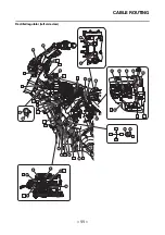
Страница 26: ...CABLE ROUTING 19 Front brake hose left and right side view A B C D E D F G G H 1 1 2 2 2 3 2 3 4 1...
Страница 47: ...FUEL TANK 40...
Страница 63: ...SIGNALING SYSTEM 56...
Страница 85: ...ABS ANTI LOCK BRAKE SYSTEM 78...
Страница 86: ...ELECTRICAL COMPONENTS 79 EAS20089 ELECTRICAL COMPONENTS 1 2 3 4 5 5 6 7 8 9 11 12 13 14 10 15 16 17 18...
Страница 89: ...ELECTRICAL COMPONENTS 82...
Страница 91: ......
Страница 92: ......


