MULTI-FUNCTION DISPLAY
1-17
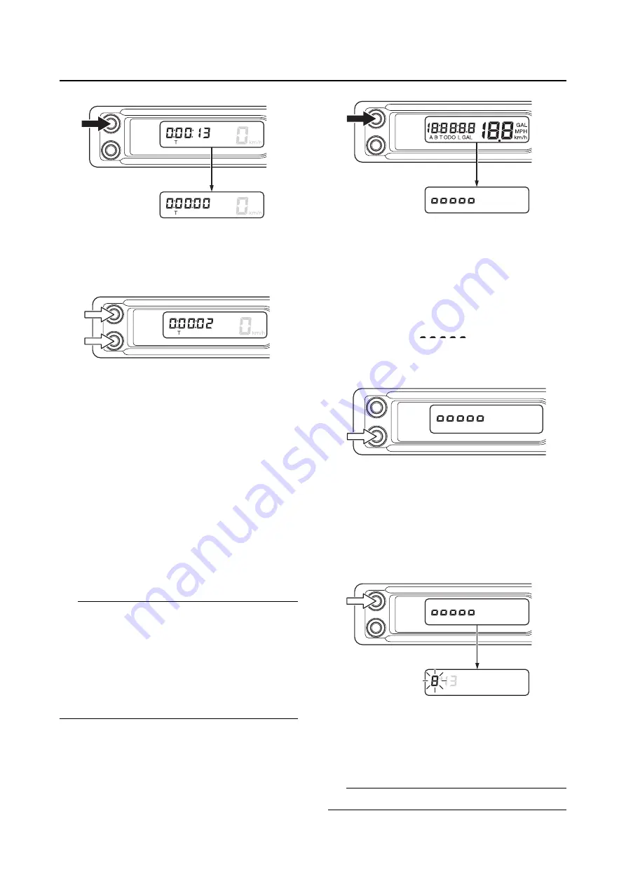
3. Push the A button and B button simultane-
ously once again to restart the measurement.
EAM30622
SETTING MODE
Shifting to the setting mode
1. Keep the A button pushed and activate the
display.
After the display is activated, when the setting
mode is shifted to the first backlight bright-
ness setting, release the A button.
The display will change in the order:
Setting the backlight brightness
Setting
the clock time (hour)
Setting the clock time
(minute)
Setting the unit
Setting the fuel
consumption correction
Setting the back-
light brightness
TIP
If one of the following situations occurs while
performing the setting mode, the setting value
that is displayed will be accepted even if the set-
tings are not finished, and the setting mode dis-
play will disappear.
•
The display has been turned off
•
The vehicle has been moved
•
A communication error has occurred.
Setting the backlight brightness
1. Push the B button and adjust the brightness.
2. When the B button is pushed, the number of
segments will increase one by one as the me-
ter brightness increases.
If you push the B button when 5 segments
(highest setting) are selected, the segments
will go back to “
” and the brightness
of the meter will become low.
3. When the brightness has been adjusted as
desired, push the A button.
The setting of the meter brightness will then
be kept and the display of the multifunction
meter will shift to the clock time setting.
Setting the clock time
Setting the hour
1. Push the B button to adjust the hour.
A long push on the button will fast-forward the
time.
TIP
The digits capable of setting go on flashing.
Содержание WR250F 2023
Страница 8: ......
Страница 15: ...LOCATION OF IMPORTANT LABELS 1 5...
Страница 16: ...LOCATION OF IMPORTANT LABELS 1 6 AUS NZL ZAF EUR...
Страница 56: ...TIGHTENING TORQUES 2 15...
Страница 90: ...ELECTRICAL SYSTEM 3 32...
Страница 94: ...GENERAL CHASSIS 4 2 a Projection b Slot c Rib side cover d Rib rear fender a a a 1 1 c c b b d d...
Страница 135: ...1 2 3 4 5 6 7 8 9 10 FUEL SYSTEM FUEL TANK 6 1 REMOVING THE FUEL TANK 6 1 INSTALLING THE FUEL TANK 6 1...
Страница 138: ...FUEL TANK 6 3...
Страница 146: ...ELECTRICAL COMPONENTS 7 7...
Страница 160: ...SELF DIAGNOSTIC FUNCTION AND DIAGNOSTIC CODE TABLE 8 13...
Страница 170: ...CHASSIS 9 9...
Страница 172: ...PRINTED IN JAPAN E...


