13
Soavo-900SW
Soavo-900SW
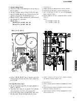
1. 出力電圧の確認
a. MAIN (1) P.C.B. の CB22 を外し、無負荷にします。
b. 本機の電源コードを AC コンセントに接続します。
c. 本機 主電源 入 / 切 キーを 入 にして、 STANDBY/
ON
キーを押します。
d. SP +と GND 間および SP −と GND 間の DC 電圧を測定
します。
正常値
SP +と GND 間:
+50V
±
5V
SP −と GND 間:
+50V
±
5V
1. Output Voltage Check
a. Disconnect CB22 of the MAIN (1) P.C.B. so that no
load is applied.
b. Connect the power cable of this unit to the AC outlet.
c. Set the “POWER ON/OFF” key of this unit to the “ON”
position and press the “STANDBY/ON” key.
d. Measure the DC voltage between SP+ and GND and
also between SP– and GND.
Normal value
between SP+ and GND: +50V
±
5V
between SP– and GND: +50V
±
5V
e. 本機の
主電源 入 / 切
キーを
切
にして、電源コー
ドを AC コンセントから抜きます。
2. 出力波形の確認
a. 信号発生器の出力信号を INPUT 3 L/MONO に接続しま
す。
b. スピーカーユニットに接続されているコネクタ端子を外
し、4 Ω負荷抵抗に接続します。
c. 信号発生器の電源を入れ、正弦波・100Hz・出力レベル
最小に設定します。
e. Set the “POWER ON/OFF” key of the main unit to the
“OFF” position and disconnect the power cable from
the AC outlet.
2. Output Waveform Check
a. Connect the output signal from the signal generator to
INPUT 3 L/MONO.
b. Disconnect the connector connected to the speaker
unit and connect it to the 4-ohm load resistor.
c. Turn on the power of the signal generator and set for
the sine wave, 100Hz and output level minimum.
SP–
SP+
GND
MAIN (1) P.C.B. (side A)
SP+
SP–
GND
Содержание Soavo-900SW
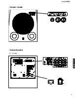
Страница 3: ...3 Soavo 900SW Soavo 900SW FRONT PANEL REAR PANELS U C models ...
Страница 4: ...4 Soavo 900SW Soavo 900SW R model T model K model A model ...
Страница 5: ...5 Soavo 900SW Soavo 900SW B G models L model J model ...
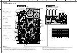
Страница 15: ...15 Soavo 900SW Soavo 900SW DIGITAL P C B VR101 0 80 mV MAIN 1 P C B ...
Страница 36: ...Soavo 900SW Soavo 900SW ...


