background image

43

POWR

TR

RXW10L

Order

Job/Part

Q’ty

Remarks

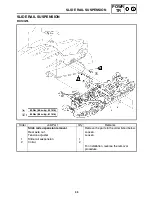
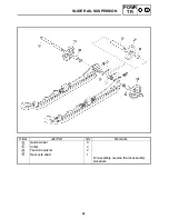
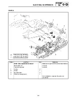
Slide rail suspension removal

Remove the parts in the order listed below.

Rear axle nut

Loosen.

Tension adjuster

Loosen.

1

Collar

2

2

Shaft

1

3

Guide wheel

2

4

Slide rail suspension

1

For installation, reverse the removal
procedure.

72 Nm (7.2 m•kg, 52 ft•lb)

84 Nm (8.4 m•kg, 61 ft•lb)

SLIDE RAIL SUSPENSION

Содержание RX10H

Страница 1: ...SERVICE MANUAL ...

Страница 2: ... S A is expressly prohibited Printed in U S A P N LIT 12618 02 28 HOW TO USE THIS MANUAL Particularly important information is distin guished in this manual by the following nota tions The Safety Alert Symbol means ATTENTION BE ALERT YOUR SAFETY IS INVOLVED Failure to follow WARNING instructions could result in severe injury or death to the snowmo bile operator a bystander or a person inspect ing ...

Страница 3: ... Electrical 9 Specifications Illustrated symbols 10 to 16 are used to identify the specifications which appear 10 Filling fluid 11 Lubricant 12 Tightening 13 Wear limit clearance 14 Engine speed 15 Special tool 16 Ω V A Illustrated symbols 17 to 25 in the exploded dia gram indicate grade of lubricant and location of lubrication point 17 Apply locking agent LOCTITE 18 Apply Yamabond No 5 19 Apply e...

Страница 4: ... 5 4 INSP ADJ GENERAL INFORMATION PERIODIC INSPECTIONS AND ADJUSTMENTS POWER TRAIN ENGINE COOLING SYSTEM ELECTRICAL SPECIFICATIONS GEN INFO 2 3 POWR TR ENG COOL ELEC SPEC CHASSIS CHAS 7 CARBURETION CARB INDEX ...

Страница 5: ...17 THROTTLE OVERRIDE SYSTEM T O R S CHECK 2 18 COMPRESSION PRESSURE MEASUREMENT 2 18 ENGINE OIL LEVEL INSPECTION 2 20 ENGINE OIL REPLACEMENT 2 22 CRANKCASE BREATHER HOSE INSPECTION 2 24 CABURETOR JOINTS INSPECTION 2 24 EXHAUST SYSTEM INSPECTION 2 25 POWER TRAIN 2 26 SHEAVE OFFSET ADJUSTMENT 2 26 DRIVE V BELT 2 27 ENGAGEMENT SPEED CHECK 2 29 PARKING BRAKE ADJUSTMENT 2 30 BRAKE LEVER ADJUSTMENT 2 30...

Страница 6: ...DRIVE CHAIN HOUSING INSTALLATION 4 27 BRAKE 4 28 BRAKE PAD REPLACEMENT 4 29 BRAKE CALIPER DISASSEMBLY 4 32 BRAKE CALIPER INSPECTION AND REPAIR 4 32 BRAKE CALIPER ASSEMBLY 4 33 BRAKE CALIPER INSTALLATION 4 33 INSPECTION 4 35 BRAKE MASTER CYLINDER ASSEMBLY 4 35 INSTALLATION 4 35 SLIDE RAIL SUSPENSION 4 36 RX10 RX10S RX10R RX10RS 4 36 RX10M RX10MS 4 41 INSPECTION 4 46 ASSEMBLY 4 47 INSTALLATION 4 47 ...

Страница 7: ...USTMENT 7 10 FUEL PUMP 7 12 INSPECTION 7 12 INSTALLATION 7 12 CHAPTER 8 ELECTRICAL SWITCH INSPECTION 8 1 SWITCH INSPECTION 8 1 INSPECTING A SWITCH SHOWN IN THE MANUAL 8 1 IGNITION SYSTEM 8 2 CIRCUIT DIAGRAM 8 2 TROUBLESHOOTING 8 4 A C MAGNETO 8 5 SPARK PLUG 8 5 IGNITION SPARK GAP 8 6 IGNITION COIL 8 6 THROTTLE OVERRIDE SYSTEM T O R S 8 7 HANDLEBAR SWITCH RIGHT 8 8 CARBURETOR SWITCH 8 8 MAIN SWITCH...

Страница 8: ...M 8 42 CIRCUIT DIAGRAM 8 42 TROUBLESHOOTING 8 44 CARBURETOR HEATER RELAY 8 45 CARBURETOR HEATER 8 45 SELF DIAGNOSIS 8 46 FUEL METER FUEL LEVEL WARNING INDICATOR AND THE WARNING LIIGHT 8 46 COOLANT TEMPERATURE WARNING LIGHT AND THE WARNING LIGHT 8 47 SELF DIAGNOSIS WARNING INDICATOR AND THE WARNING LIGHT 8 47 CHAPTER 9 SPECIFICATIONS GENERAL SPECIFICATIONS 9 1 MAINTENANCE SPECIFICATIONS 9 4 ENGINE ...

Страница 9: ...RAME SERIAL NUMBER The frame serial number 1 is located on the right hand side of the frame just below the front of the seat ENGINE SERIAL NUMBER The engine serial number 1 is located on the left hand side of the crankcase Designs and specifications are subject to change without notice ...

Страница 10: ...rts that have been mated through normal wear Mated parts must be reused or replaced as an assembly 4 During disassembly of the machine clean all parts and place them in trays in the order of disassembly This will speed up as sembly time and help ensure that all parts are reinstalled correctly 5 Keep all parts away from any source of fire 6 Be sure to keep to the tightening torque specifications Wh...

Страница 11: ...r manufacturer s marks or numbers facing outwards In other words the stamped let ters must be on the side exposed to view When installing oil seals apply a light coating of lightweight lithium base grease to the seal lips Oil the bearings liberally when installing Do not use compressed air to spin the bearings dry This causes damage to the surface of the bearings CIRCLIPS All circlips should be in...

Страница 12: ...eave gauge P N YS 42421 1 15 mm offset for U S A Canada This gauge is used to measure the sheave distance and for offset ad justment SDial gauge P N YU 03097 for U S A Canada 90890 03097 for Europe This gauge is used for run out measurement SFuel level gauge P N YM 01312 A for U S A Canada 90890 01312 for Europe This gauge is used to measure the fuel level in the float chamber SCarburetor angle dr...

Страница 13: ...nizer P N YU 8030 for U S A Canada 90890 03094 for Europe This guide is used to synchronize the carburetors SCompression gauge set P N YU 33223 compression gage for U S A Canada 90890 03081 for Europe P N YU 33223 3 adapter for U S A Canada for Europe 90890 04136 for Europe These tools are used to measure engine compression SValve spring compressor set quick release attachment P N YM 04019 valve s...

Страница 14: ...90890 04113 for Europe P N YM 4118 ø4 5 for U S A Canada 90890 04118 for Europe These tools are used to rebore the new valve guides SValve lapper P N 90890 04101 for Europe This tools is needed to remove and install the valve lifter SPiston ring compresser P N YM 8037 for U S A Canada 90890 05158 for Europe This tool is used to compress the piston rings when installing the pis ton into the cylinde...

Страница 15: ...and assembling the primary sheave SClutch separator adapter P N YS 34480 for U S A Canada 90890 01740 for Europe This tool is used when disassembling and assembling the primary sheave SYXR clutch bushing jig kit P N YS 39752 for U S A Canada This tool is used for removal and installation of primary clutch weight and roller bushings SClutch bushing press P N YS 42424 for U S A Canada This tool is u...

Страница 16: ...ment is necessary for checking the electrical components SElectro tester P N YU 33260 A for U S A Canada 90890 03021 for Europe This instrument is invaluable for checking the electrical system SSpeedometer unit test coupler P N YS 45686 for U S A Canada 8EK 82507 09 For Europe This tool is used for checking the speedometer unit SInductive self powered tachometer P N YU 8036 B for U S A Canada 9079...

Страница 17: ...Every 40 000 km 25 000 mi Engine oil Check oil level F Engine oil Replace F F Engine oil filter cartridge Replace F Every 20 000 km 12 000 mi Fuel Check fuel level F Fuel filter Check condition Replace if necessary F Fuel line Check fuel hose for cracks or damage Replace if necessary F Engine coolant Check coolant level F Engine coolant Air bleed the cooling system if necessary F Check the throttl...

Страница 18: ...ating elevation is changed Primary and secondary clutches Inspect sheaves for wear damage Inspect weights rollers and bushings for wear for primary Inspect ramp shoes bushings for wear for secondary Replace if necessary F Lubricate with specified grease F Steering column bearing Lubricate with specified grease F Ski and front suspension Lubricate with specified grease F Suspension component Lubric...

Страница 19: ...Out of specification Regap Use a wire thickness gauge Spark plug gap 0 7 X 0 8 mm 0 028 X 0 031 in If necessary clean the spark plugs with a spark plug cleaner Standard spark plug CR9E NGK Before installing a spark plug clean the gasket surface and spark plug surface 4 Install SSpark plugs Spark plug 13 Nm 1 3 mSkg 9 4 ftSlb Finger tighten a the spark plug before torquing b it to specification ...

Страница 20: ...Place the machine on a level surface 2 Remove SIntake silencer Refer to CARBURETORS in CHAPTER 7 3 Remove SCoolant filler cap 1 Do not remove the coolant filler cap 1 when the engine is hot Pressurized scalding hot fluid and steam may be blown out which could cause serious injury When the engine has cooled place a thick rag or a towel over the coolant filler cap Slowly turn the cap counterclockwis...

Страница 21: ...ft up the front of the machine to drain the cool ant completely Coolant is poisonous It is harmful or fatal if swallowed SIf coolant is swallowed induce vomiting immediately and get immediate medical attention SIf coolant splashes in your eyes thorough ly wash them with water and consult a doc tor SIf coolant splashes on your skin or clothes quickly wash it away with soap and water 10 Connect SCoo...

Страница 22: ...col antifreeze containing corrosion inhibitors Coolant mixing ratio coolant water 3 2 60 40 Total amount 4 7 L 4 14 lmp qt 4 97 US qt SHard water or salt water is harmful to en gine parts If soft water is not available use boiled or distilled water SDo not use water containing impurities or oil 15 Bleed the air from the cooling system 16 Inspect SCooling system Decrease of pressure leaks Repair as...

Страница 23: ...r bleeding steps SLift up the tail of the machine SRemove the bleed bolt 1 on the heat ex changer SWhile slowly adding coolant to the coolant fill er drain the coolant until no more air bubbles appear STighten the bleed bolt 1 Bleed bolt 13 Nm 1 3 mSkg 9 4 ftSlb SAdd coolant to the coolant cold level a SInstall the coolant filler cap Apply and lock the parking brake Start the en gine and run it at...

Страница 24: ...t wear could occur or the machine could unexpectedly move forward if the clutch engages SOperate the engine only in a well ventilated area SRemove the coolant filler cap and bleed the cooling system again as described above No air bubbles OK SAdd coolant to the specified level SPour coolant into the coolant reservoir 1 until the coolant level reaches the COLD LEVEL level mark 2 3 Install SRear cov...

Страница 25: ...PTER 5 STiming plug 3 Measure SValve clearance Out of specification Adjust Valve clearance cold Intake valve 0 11 X 0 20 mm 0 0043 X 0 0079 in Exhaust valve 0 21 X 0 25 mm 0 0083 X 0 0098 in Checking steps STurn the crankshaft clockwise SWhen piston 4 is at TDC on the compression stroke align the TDC mark a on the A C magneto rotor with the mark b on the A C magneto cover STurn the crankshaft cloc...

Страница 26: ...shaft clockwise as specified in the following table B Degrees that the crankshaft is turned clockwise C Cylinder D Combustion cycle 2 Cylinder 180_ 4 Cylinder 360_ 3 Cylinder 540_ 4 Remove SIntake camshaft SExhaust camshaft SRefer to CAMSHAFTS in CHAPTER 5 SWhen removing the timing chain and cam shafts fasten a wire to the timing chain to re trieve it if it falls into the crankcase 5 Adjust SValve...

Страница 27: ...ide that touches the valve lifter SSince valve pads of various sizes are originally installed the valve pad number must be rounded in order to reach the closest equiva lent to the original SRound off the original valve pad number ac cording to the following table Last digit Rounded value 0 or 2 0 5 5 8 10 EXAMPLE Original valve pad number 148 thickness 1 48 mm 0 058 in Rounded value 150 SLocate th...

Страница 28: ...160 pad 120 125 130 135 140 145 150 155 160 165 170 175 180 185 190 195 200 205 210 215 220 225 230 235 240 0 00 X 0 02 120 125 130 135 140 145 150 155 160 165 170 175 180 185 190 195 200 205 210 215 0 03 X 0 07 120 125 130 135 140 145 150 155 160 165 170 175 180 185 190 195 200 205 210 215 220 0 08 X 0 12 120 125 130 135 140 145 150 155 160 165 170 175 180 185 190 195 200 205 210 215 220 225 0 13...

Страница 29: ... 2 ftSlb SRefer to CAMSHAFTS in CHAPTER 4 SLubricate the camshaft caps camshaft lobes and camshaft journals SFirst install the exhaust camshaft SAlign the camshaft marks with the camshaft cap marks SRotate the crankshaft clockwise several turns to seat the parts SMeasure the valve clearance again SIf the valve clearance is still out of specifica tion repeat all of the valve clearance adjust ment s...

Страница 30: ...meter near the spark plug Carburetor synchronizer 90890 03094 YU 8030 Engine tachometer 90793 80009 YU 8036 B 3 Start the engine and let it warm up for several minutes 4 Inspect SEngine idle speed Out of specification Adjust Refer to ENGINE IDLE SPEED ADJUST MENT Engine idle speed 1 350 100 r min 1 250 X 1 450 r min 5 Adjust SCarburetor synchronization Adjustment steps SSynchronize carburetor 2 to...

Страница 31: ...ntil both gauges read the same SSynchronize carburetor 2 to carburetor 1 by turning the synchronizing screw 3 in either direction until both gauges read the same Vacuum pressure at engine idling speed 35 kPa 0 35 kg cm2 4 98 psi The difference in vacuum pressure between two carburetors should not exceed 1 33 kPa 0 01 kg cm2 0 19 psi 6 Measure SEngine idle speed Out of specification Adjust 7 Adjust...

Страница 32: ...up for several minutes 2 Install SEngine tachometer near the spark plug Engine tachometer 90793 80009 YU 8036 B 3 Measure SEngine idle speed Out of specification Adjust Engine idle speed 1 350 100 r min 1 250 X 1 450 r min 4 Adjust SEngine idle speed STurn the throttle stop screw 1 in or out until the specified engine idle speed is obtained Turning in Idle speed is increased Turning out Idle speed...

Страница 33: ...hrottle cable free play a Out of specification Adjust Throttle cable free play 2 0 X 3 0 mm 0 08 X 0 12 in 2 Adjust SThrottle cable free play Adjustment steps SLoosen the locknut 1 STurn the adjusting nut 2 in or out until the spe cified free play is obtained Turning in Free play is increased Turning out Free play is decreased STighten the locknut After adjusting the free play turn the handlebar t...

Страница 34: ...utting your thumb above and forefinger below between the throttle lever pivot 1 and stop switch hous ing 2 While holding as described above press the throttle lever 3 gradually The T O R S will operate and the engine should run between 2 800 and 3 000 r min If the engine does not run between 2 800 and 3 000 r min stop the engine by turning the main switch to the OFF position and check the electric...

Страница 35: ...valve surfaces and piston crown for carbon deposits Below the minimum pressure Squirt a few drops of oil into the affected cylinder and measure again Refer to the following table Compression pressure with oil applied into cylinder Reading Diagnosis Higher than without oil Piston ring s wear or damage Repair Same as without oil Piston valves cylinder head gasket or piston possibly defective Repair ...

Страница 36: ... 9 4 ftSlb ENGINE OIL LEVEL INSPECTION 1 Inspect SEngine oil level Do not run the engine with too much or not enough oil in the oil tank Oil could flow into the intake silencer and the engine could be damaged Inspection steps SPlace the snowmobile on a level surface and apply the parking brake SStart the engine warm it up for 10 X 15 min utes and then turn off SDisconnect the oil level gauge coupl...

Страница 37: ...in atmospheric temperatures API standard API SE SF SG or higher SAE 5W 30 Do not allow foreign materials to enter the crankcase Before checking the engine oil level wait a few minutes until the oil has settled SStart the engine warm it up for several min utes and then turn it off SCheck the engine oil level again Before checking the engine oil level wait a few minutes until the oil has settled SUs...

Страница 38: ...stick SCylinder head cap SOil pan drain bolt 1 SOil tank drain bolt 2 4 Drain SEngine oil completely from the oil pan and oil tank 5 If the oil filter cartridge is also to be replaced perform the following procedure Replacement steps a Remove air box b Remove battery c Remove battery bracket d Then remove oil filter SRemove the oil filter cartridge 1 with an oil fil ter wrench 2 When remove the oi...

Страница 39: ...gaskets Drain bolt oil tank 16 Nm 1 6 mSkg 12 ftSlb Drain bolt oil pan 30 Nm 3 0 mSkg 22 ftSlb 7 Fill SEngine oil with the specified amount of the recomen ded engine oil Add 2 0 L 1 8 lmp qt 2 1 US qt of the recom mended engine oil to the oil tank and then install and tighten the oil level gauge dipstick and the cylinder head cap Quantity Total amount 3 8 L 3 3 Imp qt 4 0 US qt Periodic oil change...

Страница 40: ...seize SCheck the engine oil passages the oil filter and the oil pump for damage or leakage SStart the engine after solving the problem s and check the engine oil pressure again Tighten the oil gallery bolt to specification Oil gallery bolt 10 Nm 1 0 mSkg 7 2 ftSlb CRANKCASE BREATHER HOSE INSPECTION 1 Inspect SCrankcase breather hose 1 Cranks damage Replace Loosen connection Connect properly Make s...

Страница 41: ...25 Nm 2 5 mSkg 18 ftSlb SMuffler 2 STightening torque Bolt muffler 16 Nm 1 6 mSkg 12 ftSlb SExhaust pipe 3 STightening torque Bolt exhaust pipe 25 Nm 2 5 mSkg 18 ftSlb SMuffler band 4 STightening torque Bolt muffler band 20 Nm 2 0 mSkg 14 ftSlb SExhaust pipe band 5 STightening torque Bolt exhaust pipe band 9 Nm 0 9 mSkg 6 5 ftSlb Cracks damage Replace SGaskets 6 SGaskets 7 SGasket 8 Exhaust gas le...

Страница 42: ...nt steps SApply the brake to lock the secondary sheave SRemove the bolt Secondary sheave 1 washer 2 and secondary sheave 3 SAdjust the sheave offset by adding or remov ing shim s 4 Adding shim Offset is increased Removing shim Offset is decreased Shim size Part Number Thickness 90201 25526 2 0 mm 0 08 in SInstall the secondary sheave bolt secondary sheave and washer Bolt secondary sheave 64 Nm 6 4...

Страница 43: ...90201 222F0 0 5 mm 0 02 in 90201 225A4 1 0 mm 0 04 in DRIVE V BELT When installing the new V belt make sure that it is positioned from 1 5 mm 0 06 in above the edge of the secondary sheave to 0 5 mm 0 02 in below the edge a If the V belt is not positioned correctly the clutch engagement speed will be changed The machine may move unexpectedly when the engine is started Adjust the V belt position by...

Страница 44: ...ight 0 5 X 1 5 mm 0 02 X 0 06 in 2 Adjust the position of the V belt by removing or adding a spacer 1 on each adjusting bolt 2 V belt position Adjustment More than 1 5 mm 0 06 in above the edge Remove a spacer From 1 5 mm 0 06 in above the edge to 0 5 mm 0 02 in below the edge Not necessary It is correct More than 0 5 mm 0 02 in below the edge Add spacer Part number Thickness 90201 061H1 0 5 mm 0 ...

Страница 45: ...eck the primary and secondary sheaves 6 Measure SDrive V belt circumference a Out of specification Replace V belt circumference 1 129 X 1 137 mm 44 4 X 44 8 in ENGAGEMENT SPEED CHECK 1 Place the machine on a level surface of hard packed snow 2 Inspect SClutch engagement speed Inspection steps SStart the engine and open the throttle lever gradually SCheck the engine speed when the machine starts mo...

Страница 46: ...fied distance a is obtained Turning in Distance a is increased Turning out Distance a is decreased STighten the locknut 3 Measure SBrake pad clearance b Out of specification Adjust Brake pad clearance 1 5 X 2 0 mm 0 059 X 0 079 in 4 Adjust SBrake pad clearance Adjustment steps SLoosen the locknut 1 STurn the adjuster 2 in or out to until the speci fied clearance between the brake pad 3 and brake d...

Страница 47: ...vel Recommended brake fluid DOT 4 For a correct reading of the brake fluid level make sure that the top of the handlebar brake master cylinder reservoir is horizontal Brake fluid may corrode painted surfaces or plastic parts Always clean up spilled fluid immediately SUse only the designated brake fluid Other fluids may deteriorate the rubber seals causing leakage and poor brake perfor mance SRefil...

Страница 48: ...BLEEDING HYDRAULIC BRAKE SYSTEM Bleed the brake system in the following cases SThe system has been disassembled SA brake hose is loosened or removed SThe brake fluid has been very low SBrake operation is faulty If the brake system is not properly bled a loss of braking performance may occur 1 Bleed SBrake system Air bleeding steps SFill the brake master cylinder reservoir with the proper brake flu...

Страница 49: ...it has been reached then release the lever SRepeat steps a to d until all of the air bubbles have disappeared from the fluid STighten the bleed screws Bleed screw 6 Nm 0 6 mSkg 4 3 ftSlb If bleeding is difficult it may be necessary to let the brake fluid settle for a few hours Repeat the bleeding procedure when the tiny bubbles in the system have disappeared SAdd brake fluid to the proper level Re...

Страница 50: ...t the dipstick There is a magnet attached to the end of the dipstick It is used to remove any metal par ticles that may accumulate in the drive chain housing Be sure to SPull the dipstick out slowly and gently so the metal particles do not fall off the mag net back into the drive chain housing SWipe off the magnet before reinserting the dipstick into the drive chain housing SRemove the dipstick an...

Страница 51: ...the drain hole SRemove the oil drain bolt 1 and drain the oil Be sure to remove any oil from the heat pro tector SInstall the oil drain bolt 1 Oil drain bolt 16 Nm 1 6 mSkg 12 ftSlb Recommended oil Gear oil API GL 3 SAE 75 or 80 Oil capacity 0 25 L 8 8 Imp oz 8 5 US oz Chain slack adjustment 1 Adjust SDrive chain slack Adjustment steps SLoosen the locknut 1 STurn the adjusting bolt 2 in until it i...

Страница 52: ...spect the condition of the track frequent ly Replace the track if it is damaged to a level where the fabric reinforcement mate rial is visible 1 Lift the rear of the machine onto a suitable stand to raise the track off the ground 2 Measure STrack deflection a Using a spring scale 1 pull down on the center of the track with 100 N 10 kg 22 lb of force Out of specification Adjust Track deflection 25 ...

Страница 53: ...ified amount is obtained Track deflection More than specified Less than specified Left adjuster Turn in Turn out Right adjuster Turn in Turn out The adjusters should be turned an equal amount SRecheck the alignment and deflection If necessary repeat steps a to c until the specified amount is obtained STighten the rear axle nut Nut rear axle 75 Nm 7 5 mSkg 54 ftSlb SLIDE RUNNER INSPECTION 1 Inspect...

Страница 54: ...e runners from overheat ing avoid sustained high speed usage in areas such as icy trails frozen lakes and rivers that have minimal snow coverage An overheated track will be weakened internally which may cause failure or damage Off trail riding Avoid off trail riding until there is sufficient snow coverage It generally takes several feet of snow to provide a good overall base to properly cover debr...

Страница 55: ...c ski thickness b Out of specification Replace Ski runner wear limit 8 mm 0 31 in Plastic ski wear limit 24 mm 0 95 in To avoid scratching wearing and damaging the plastic skis be careful when loading and unloading the snowmobile and avoid riding in areas with little or no snow and on sur faces with sharp edges such as concrete curbs etc ...

Страница 56: ...d relay rod ends are installed securely in position If free play still exists check the steering bearing front sus pension links and ski mounting area for wear Replace if necessary Toe out adjustment 1 Place the machine on a level surface 2 Check SSki toe out a c SSki stance b Point the skis forward Out of specification Adjust Ski toe out 0 X 15 mm 0 X 0 59 in Ski stance center to center RX10 RX10...

Страница 57: ...tie rod 2 can be rotated freely through the ball joint travel If not loosen the locknut 1 and re position the ball joint so that the tie rod 2 can be rotated freely Tighten the locknuts to specification A Left side B Right side C Inside LUBRICATION Brake lever throttle lever and throttle cable end 1 Lubricate the brake lever pivot throttle lever and the ends of the throttle cables Recommended lubr...

Страница 58: ...P ADJ A A B C Front and rear suspension 1 Use a grease gun to inject grease into the nipples 1 Recommended lubricant Esso Beacon 325 Grease or Aeroshell Grease 7A A Front B Rear RX10 RX10S RX10R RX10RS C Rear RX10M RX10MS ...

Страница 59: ...ll at that height 4 With a person sitting on the machine apply the parking brake start the engine and let it idle 5 Switch on the headlight s high beam and check the height of the projected beam on the wall The projection should be at the posi tion marked in step 3 or 1 2_ lower set range S 3 0 m 10 ft 7 6 m 25 ft 26 mm 1 0 in 66 mm 2 6 in D Distance S Set range 6 Adjust SHeadlight beam vertically...

Страница 60: ...ause severe burns or permanent eye injury First aid in case of bodily contact External SSKIN Wash with water SEYES Flush with water for 15 minutes and get immediate medical attention Internal SDrink large quantities of water or milk fol lowed with milk of magnesia beaten egg or vegetable oil Get immediate medical attention SThis is a sealed battery Never remove the sealing caps because the balance...

Страница 61: ...y terminals 1 Disconnect SBattery leads from the battery terminals First disconnect the negative lead 1 then the positive lead 2 2 Remove SBattery 3 Inspect SBattery charge Inspection steps SConnect a pocket tester to the battery termi nals Tester positive lead battery positive terminal Tester negative lead battery negative terminal SThe charge state of a MF battery can be checked by measuring its...

Страница 62: ...th the battery mounted on the motorcycle disconnect the negative lead from the battery terminal STo reduce the chance of sparks do not plug in the battery charger until the battery charger leads are connected to the battery SBefore removing the battery charger lead clips from the battery terminals be sure to turn off the battery charger SMake sure that the battery charger lead clips are in full co...

Страница 63: ...hecking steps If the current does not exceed the standard charging current after 5 minutes replace the battery If charging requires more than 5 hours it is advisable to check the charging current after a lapse of 5 hours If there is any change in the amperage readjust the voltage to obtain the standard charging current Measure the battery open circuit voltage after leaving the battery unused for m...

Страница 64: ...oltage is 15 V This type of battery charger cannot charge the MF battery A variable voltage charger is recommended Measure the battery open circuit voltage after leaving the battery unused for more than 30 minutes 12 8 V or more Charging is complete 12 7 V or less Recharging is required Under 12 0 V Replace the battery Set the charging time at 20 hours maximum YES NO NOTE Voltage should be measure...

Страница 65: ...nnect SBattery leads to the battery terminals First connect the positive lead 1 then the negative lead 2 7 Check SBattery terminals Dirt Clean with a wire brush Loose connection Connect properly 8 Lubricate SBattery terminals Recommended lubricant Dielectric grease ...

Страница 66: ...t tester selector to Ω 1 Pocket tester 90890 03112 YU 03112 S If the pocket tester indicates replace the fuse 2 Replace SBlown fuse Replacing steps SSet the main switch to OFF SInstall a new fuse of the correct amperage SSet the main switch to ON and verify if the electrical circuit is operational SIf the fuse immediately blows again check the electrical circuit Item Amperage Q ty Main fuse 30 A 1...

Страница 67: ...er unit Inspection steps SRemove the speedometer coupler 1 and headlight coupler 2 SConnect the speedometer unit test coupler 3 to the speedometer coupler and headlight coupler SConnect the speedometer unit test coupler leads as follows Speedometer unit test coupler lead red 4 Battery terminal Speedometer unit test coupler lead black 5 Battery terminal Speedometer unit test coupler 8EK 82507 09 YS...

Страница 68: ...en in carbure tor setting so that the pistons will not be dam aged or will not seize Before performing the carburetor tuning make sure that the following items are set to specification SEngine idle speed SThrottle cable free play SCarburetor synchronization SStarter cable free play Carburetor tuning data 1 Standard specifications Type BSR37 Manufacturer MIKUNI I D Mark 8FA100 Main jet M J 135 Pilo...

Страница 69: ...Spark plugs 3 Check SSpark plug insulator 1 color A medium to light tan color indicates normal conditions Distinctly different color Replace the main jet 4 The main jet should be adjusted on the basis of the Main jet selection chart By checking the condition of the spark plugs it is easy to get some idea of the condition of the engine This may diagnose potential problems before engine damage occur...

Страница 70: ...TUNING INSP ADJ B Piston valve opening Fully opened Closed Fuel flow rate L hr A D E Piston valve opening A B Mid range speed tuning High speed turning C Fully opened D Closed E Low speed tuning F Guide for carburetion ...

Страница 71: ...s 10 larger than stan dard A No 2 position B No 1 position C No 3 position If the air silencer box is removed from the carburetors the change in pressure in the intake will create a lean mixture that may cause severe engine damage The air silenc er box has no effect on performance charac teristics and must be secured to the carbu retors during carburetor tuning and adjustment Also it must always b...

Страница 72: ...depending on each cylinder Make sure to rotate the screw backward after listing its present number of return rotation on each cylinder Pilot mixture screw effects Turn in STD setting Turn out Leaner Mixture Richer Mixture 2 Set the engine idle speed by turning the throttle stop screw 2 in to increase engine speed or out to decrease engine speed Engine idle speed 1 350 100 r min 1 250 X 1 450 r min...

Страница 73: ...s Adjustment Hard starting Insufficient fuel Add gasoline Excessive use of the starter or choke Return the starter lever to its seated posi tion so that the starter valve is fully closed Fuel passage is clogged or frozen S Check and if necessary clean the fuel tank air vent the fuel filter and all of the fuel passages S Check and if necessary clean the carburetor air vents fuel passages and the fl...

Страница 74: ...an it with compressed air and then install it S Make sure that the main jet is fully tightened Clogged fuel line Clean or replace the fuel line Dirty fuel tank Clean the fuel tank Air leaks into the fuel line Tighten or replace the fuel line joint Low fuel pump performance Repair or replace the fuel pump Clogged fuel filter Replace the fuel filter Clogged intake Remove any obstructions e g ice Abn...

Страница 75: ...g mm z 27 N mm 2 75 kg mm 29 4 Nm 3 00 kg mm z Spring rate 2 50 kg mm 140 lb in z 2 75 kg mm 154 lb in 3 00 kg mm 168 lb in z Wire diameter 5 8 mm 0 228 in z z 6 0 mm 0 236 in z Outside diameter 60 mm 2 36 in z z z z Weight ID 8FA 17605 00 8FA00 z z z z Weight rivet OUT Steel 17 2 with hole Steel 13 3 Steel 13 3 with hole Aluminum 13 3 with hole None rivet IN Steel 17 2 Steel 13 3 Steel 13 3 with ...

Страница 76: ...ng rate 3 25 kg mm 182 lb in z z z z Wire diameter 6 2 mm 0 244 in z z z z Outside diameter 60 mm 2 36 in z z z z Weight ID 8FA 17605 00 8FA00 z z z z Weight rivet OUT Steel 17 2 with hole Steel 13 3 Steel 13 3 with hole Aluminum 13 3 with hole None Weight rivet IN Steel 17 2 Steel 13 3 with hole Aluminum 13 3 with hole Aluminum 13 3 with hole None Weight bushing Duralon z z z z Roller outer dia 1...

Страница 77: ...able conditions wet snow icy snow hills or rough terrain however engine speed may decrease after the shifting speed has been reached A Engine speed B Good condition C Clutch shifting speed D Clutch engagement speed E Starting position F Distance travelled 800 m 2 500 ft GEAR SELECTION The reduction ratio of the driven gear to the drive gear must be set according to the snow conditions If there are...

Страница 78: ... links 1 73 68 links 1 65 70 links 1 58 70 links 39 teeth 1 95 68 links 1 86 68 links 1 77 70 links 1 70 70 links 1 63 70 links 40 teeth 2 00 68 links 1 91 70 links 1 82 70 links 1 74 70 links 1 67 70 links 3 Secondary sheave spring Part no Spring rate NSmm rad kgSmm rad Preload N mm kg mm lb in Color Wire gauge mm in No of coils Free length mm in Outside diameter mm in Standard 90508 500B1 6003 6...

Страница 79: ... Part no Cam angle Identification mark Standard Quicker upshifting during acceleration 8FA 17604 00 51 43_ 8BVFA RX10 RX10S RX10R RX10RS 8BV 17604 71 47_ 8BV71 8BV 17604 51 45_ 8BV51 RX10M RX10MS 8BV 17604 31 43_ 8BV31 Quicker backshifting 8BV 17604 11 41_ 8BV11 backshifting under load 8BV 17604 91 39_ 8BV91 ...

Страница 80: ...te 5 8 0 228 60 2 36 5 25 91 2 3 59 90501 582L7 24 5 2 50 392 40 Yellow Green Yellow 5 8 0 228 60 2 36 4 92 89 4 3 52 90501 583L0 19 6 2 00 441 45 Blue White Blue 5 8 0 228 60 2 36 5 65 95 9 3 78 90501 583L1 22 1 2 25 441 45 White White White 5 8 0 228 60 2 36 5 25 93 4 3 68 90501 583L4 22 1 2 25 343 35 White Silver White 5 8 0 228 60 2 36 5 25 89 0 3 50 90501 583L5 22 1 2 25 294 30 White Pink Whi...

Страница 81: ...ght g oz without bush and rivets Shape ID mark Standard 8CH 17605 10 35 32 1 247 8CR 17605 10 38 09 1 345 8DG 17605 00 34 26 1 209 8DJ 17605 00 37 77 1 333 8DN 17605 20 42 09 1 486 8EK 17605 00 39 00 1 376 8FA 17605 00 69 43 2 449 RX10 RX10S RX10M RX10MS RX10R RX10RS ...

Страница 82: ... Steel 10 3 0 406 2 4 0 085 90261 06028 Aluminum 10 3 0 406 0 8 0 028 Decreased 90266 06001 Aluminum 13 3 0 524 0 8 0 028 with hole Decreased Force None RX10M RX10MS 9 Rollers I D 9 mm 0 354 in Roller with bushing part number Outside diameter mm in Bushing type P N Identification mark Width Standard Effects 8CR 17624 00 14 5 0 57 Duralon 90380 09245 Grooved Machined 14 6 mm Increased force 8CR 176...

Страница 83: ...ettings Decide if the problem is with the pilot jet and adjust accordingly Check the engagement speed and shift performance Adjust the primary clutch as required Not OK Not OK Not OK Not OK Not OK Not OK Not OK Not OK OK OK OK OK OK OK OK OK OK Adjust the engine idle speed by turning the stop screw of carburetor Adjust the engine idle speed by turning the stop screw of carburetor HIGH ALTITUDE TUN...

Страница 84: ... 258 mm 260 mm g 9 84 in 10 16 in 10 24 in RX10M RX10MS Spring seat Standard p g distance Shorter z Longer Preload Harder z Softer Min Max Length 213 mm 223 mm 226 mm g 8 39 in 8 78 in 8 90 in Be sure that the left and right spring pre loads are the same This shock absorber contains highly pres surized nitrogen gas Do not tamper with or attempt to open the shock absorber assembly Do not subject th...

Страница 85: ...tics of the machine Adjustment steps SLoosen the locknut 1 STurn the adjusting nut 2 in or out to adjust the stopper band tension Adjuster thread length RX10 RX10S RX10R RX10RS 25 0 5 mm 0 98 0 02 in RX10M RX10MS 10 0 5 mm 0 39 0 02 in Longer Shorter Maximum Minimum Effects More weight Less weight on skis on skis Less weight More weight transfer transfer STighten the locknut Locknut 16 Nm 1 6 mSkg...

Страница 86: ...der z Softer Min Max Length 180 mm 190 mm 190 mm g 7 09 in 7 48 in 7 48 in This shock absorber contains highly pres surized nitrogen gas Do not tamper with or attempt to open the shock absorber assembly Do not subject the shock absorber assem bly to flames or high heat which could cause it to explode STurn the adjusting ring 1 to the proper posi tion Spring adjuster position 1 2 3 4 5 6 7 Preload ...

Страница 87: ...n 1 2 3 4 5 6 7 Preload Softer z Harder Rear Standard 4 Rear suspension full rate 1 Adjust SFull rate adjuster Adjustment steps Installation position A B C Spring rate and damping Soft Medium Hard Standard B Be sure to make this adjustment when there is no load rider or cargo on the snowmobile SLoosen the nut 1 1 2 or 3 4 turns while holding the adjusting bolt 2 securely with a wrench so it does n...

Страница 88: ... 9 mSkg 35 ftSlb Never allow the adjusting bolt to move while tightening the nut SThis model has a Easy adjust system for the Full rate adjuster The bolt has teeth on it So when the bolt is turned it rides up and down the bracket SThe nut has to be loosen first while the bolt is held in place with a wrench SThen the bolt can be turned to adjust the shock position up or down SIf the bolt is turned ...

Страница 89: ... position 1 2 3 4 Effect Increase Decrease weight transfer pitching Standard 3 Never adjust the control rods beyond the maximum range indicated on the rods with red paint 3 SWhile holding the adjusting bolt securely tight en the locknut 1 Locknut 25 Nm 2 5 mSkg 18 ftSlb Rear suspension position RX10M RX10MS 1 Adjust SRear suspension position Select the rear suspension position according to the sno...

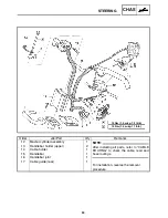
Страница 90: ... switch coupler Headlight beam switch coupler Grip warmer lead coupler Grip warmer switch lead coupler Throttle cable holder Throttle cable Brake lever holder 1 2 1 1 1 1 1 4 1 1 1 1 Remove the parts in the order listed below Disconnect Disconnect Disconnect Disconnect Disconnect Disconnect Disconnect A 10 Nm 1 0 mSkg 7 2 ftSlb 15 Nm 1 5 mSkg 11 ftSlb B STEERING CHAS CHASSIS STEERING RX10 RX10S RX...

Страница 91: ...mbly Handlebar holder upper Cable holder Handlebar Handlebar holder lower 1 2 1 1 1 After installing all parts refer to CABLE ROUTING in CHAPTER 9 to check the cable lead and hose routings For installation reverse the removal procedure NOTE A 10 Nm 1 0 mSkg 7 2 ftSlb 15 Nm 1 5 mSkg 11 ftSlb B ...

Страница 92: ... coupler Brake switch coupler Headlight beam switch coupler Grip warmer lead coupler Grip warmer switch lead coupler Throttle cable holder Throttle cable Brake lever holder 1 3 1 1 1 1 1 4 1 1 1 1 Remove the parts in the order listed below Disconnect Disconnect Disconnect Disconnect Disconnect Disconnect Disconnect A 10 Nm 1 0 mSkg 7 2 ftSlb 15 Nm 1 5 mSkg 11ftSlb B STEERING CHAS RX10M RX10MS ...

Страница 93: ...mbly Handlebar holder upper Cable holder Handlebar Handlebar holder lower 1 2 1 1 1 After installing all parts refer to CABLE ROUTING in CHAPTER 9 to check the cable lead and hose routings For installation reverse the removal procedure NOTE A 10 Nm 1 0 mSkg 7 2 ftSlb 15 Nm 1 5 mSkg 11ftSlb B ...

Страница 94: ...late Bearing Bearing holder Plate Collar Steering column 2 Tie rod Idler arm Relay arm Bushing Washer 6 1 7 1 1 3 6 6 4 6 1 2 1 2 4 2 Remove the parts in the order listed below 67 Nm 6 7 mSkg 49 ftSlb E A 25 Nm 2 5 mSkg 18 ftSlb 35 Nm 3 5 mSkg 25 ftSlb 30 Nm 3 0 mSkg 22 ftSlb 35 Nm 3 5 mSkg 25 ftSlb B C D 23 Nm 23 mSkg 17 ftSlb F ESSO beacon 325 grease or Aeroshell grease 7A 1 STEERING CHAS ...

Страница 95: ...g 25 ftSlb 30 Nm 3 0 mSkg 22 ftSlb 35 Nm 3 5 mSkg 25 ftSlb B C D 23 Nm 23 mSkg 17 ftSlb F ESSO beacon 325 grease or Aeroshell grease 7A 1 Order Job name Part name Q ty Remarks 17 18 19 Washer Collar Clip 4 2 2 For installation reverse the removal procedure STEERING CHAS ...

Страница 96: ...Inspect SBearings steering column 1 SCollars 2 Wear damage Replace SSteering column 3 bearing contact sur faces Scratches wear damage Replace 3 Inspect SRelay rod 1 STie rod 2 Bends cracks damage Replace Do not attempt to straighten bent rods This may dangerously weaken the rods 4 Check SRod end movement Rod end free play exists Replace the rod end Rod end turns roughly Replace the rod end 5 Inspe...

Страница 97: ... mSkg 25 ftSlb Nut relay rod 30 Nm 3 0 mSkg 22 ftSlb 3 Install STie rod 1 SLocknuts 2 SJoints 3 Tie rod part number Set length Tie rod length 8FA 23831 00 RX10 RX10S RX10R RX10RS 418 0 mm 16 4567 in 355 0 mm 13 9764 in 8EP 23831 00 RX10M RX10MS 374 0 mm 14 7244 in 311 0 mm 12 2441 in 4 Install STie rods 1 SMake sure that the indentation a on the tie rod faces out SThe threads on both rod ends must...

Страница 98: ...ut tie rod steering arm 35 Nm 3 5 mSkg 25 ftSlb 5 Install SSteering shaft 1 SLocknuts 2 SJoints 3 Steering Shaft part number Set length Shaft length 8FA 23840 00 227 8 mm 8 9685 in 170 0 mm 6 6929 in Make sure that the end of the steering shaft with the indentation a is connected to the steering clumn Always use new cotter pins Nut steering shaft 35 Nm 3 5 mSkg 25 ftSlb ...

Страница 99: ...Turning the steering shaft in direction Turning the handlebar in direction Turning the steering shaft in direction Turning the handlebar in direction STighten the locknuts Steering shaft 1 Loknut steering shaft 25 Nm 2 5 mSkg 18 ftSlb LOCTITE 7 Install SHandlebar SBe sure the projection on the handlebar is not installed into the area a shown SBe sure the side of the holder with the small gap b fac...

Страница 100: ...wer bracket Ski runner Collar Ski Washer Ski handle 1 1 1 6 1 1 2 1 4 1 Remove the parts in the order listed below For installation reverse the removal procedure A 11 Nm 1 1 mSkg 8 0 ftSlb 17 Nm 1 7 mSkg 12 ftSlb 19 Nm 1 9 mSkg 14 ftSlb 48 Nm 4 8 mSkg 35 ftSlb B C D ESSO beacon 325 grease or Aeroshell grease 7A 1 SKI CHAS SKI ...

Страница 101: ...lumn lower bracket 4 SSki handle 5 Wear cracks damage Replace SMounting bolt 6 SCollar 7 SBolts 8 SCollars 9 Wear damage Replace INSTALLATION 1 Install SSki column lower bracket 1 Be sure to install the ski column lower bracket with the arrow mark a pointing forward the tip of the ski ...

Страница 102: ...r Bushing Connecting rod Stabilizer arm 1 1 1 1 1 1 1 1 2 4 1 1 Remove the parts in the order listed below Refer to SKI 65 Nm 6 5 mSkg 47 ftSlb E A 45 Nm 4 5 mSkg 33 ftSlb 37 Nm 3 7 mSkg 27 ftSlb 40 Nm 4 0 mSkg 29 ftSlb 35 Nm 3 5 mSkg 25 ftSlb B C D 34 Nm 3 4 mSkg 25 ftSlb F ESSO beacon 325 grease or Aeroshell grease 7A 1 11 Nm 1 1 mSkg 8 0 ftSlb G FRONT SUSPENSION CHAS FRONT SUSPENSION ...

Страница 103: ...r installation reverse the removal procedure 65 Nm 6 5 mSkg 47 ftSlb E A 45 Nm 4 5 mSkg 33 ftSlb 37 Nm 3 7 mSkg 27 ftSlb 40 Nm 4 0 mSkg 29 ftSlb 35 Nm 3 5 mSkg 25 ftSlb B C D 34 Nm 3 4 mSkg 25 ftSlb F ESSO beacon 325 grease or Aeroshell grease 7A 1 11 Nm 1 1 mSkg 8 0 ftSlb G FRONT SUSPENSION CHAS ...

Страница 104: ...the gas chamber SDo not subject the shock absorber to flames or any other source of high heat This may cause the unit to explode due to excessive gas pressure SDo not deform or damage the gas chamber in any way Gas chamber damage will re sult in poor damping performance INSPECTION 1 Inspect SShock absorber 1 Oil gas leaks bends damage Replace 2 Inspect SSki column 1 SSteering arm 2 Cracks bends da...

Страница 105: ...nstall SSteering arm 1 SAlign the punch mark a on the ski column with the punch mark b on the steering arm SInstall sections c without any gaps Nut steering arm 35 Nm 3 5 mSkg 25 ftSlb 2 Install SStabilizer 1 SStabilizer arm 2 Install so that the angle shift between the right side stabilizer arm and the left stabilizer arm can be within 6_ Nut stabilizer arm 11 Nm 1 1mSkg 8 0 ftSlb ...

Страница 106: ...ing and the ski spindle camber before adjusting the ski toe out since either of those adjustments may affect the ski toe out setting Point the skis straight forward and measure the amount of ski toe out A Ski toe out 0 X 15 mm 0 X 0 59 in a b Toe out Refer to STEERING SYSTEM in CHAPTER 2 ...

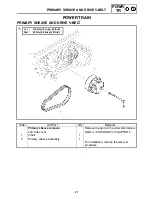
Страница 107: ...ide cover V belt Primary sheave assembly 1 1 1 A 1st 60 Nm 6 0 mSkg 43 ftSlb 2nd 120 Nm 12 mSkg 85 ftSlb Remove the parts in the order listed below For installation reverse the removal procedure PRIMARY SHEAVE AND DRIVE V BELT POWR TR POWER TRAIN PRIMARY SHEAVE AND DRIVE V BELT ...

Страница 108: ...isassemble the parts in the order listed below Left handed thread For assembly reverse the disassembly procedure A 6 Nm 0 6 mSkg 4 3 ftSlb 14 Nm 1 4 mSkg 10 ftSlb 200 Nm 20 0 mSkg 145 ftSlb B C D Clean the threads Apply LOCTITE648 as illustrated in And then tighten the spider The spider must be turned counterclockwise to be tightened a 16 mm 0 63 in b 30 mm 1 18 in 1 2 3 4 5 6 7 8 9 10 11 12 13 14...

Страница 109: ... DISASSEMBLY 1 Remove SFixed sheave 1 SStopper 2 SSliding sheave 3 SBushing 4 SSpider 5 Removal steps SImmerse the primary sheave assembly in 80 X 100_C 176 X 212_F water for several minutes SAttach the lower piece of the clutch spider separator 6 onto a rigid table using suitable mounting bolts Then install the clutch separator adapter 7 onto the separator Clutch spider separator 90890 01711 YS 2...

Страница 110: ...ider and turn the special tool clockwise to loosen the spider Clutch spider separator bar wrench 90890 01711 YS 28890 B SThe spider has a left handed thread SSince a high torque is required to loosen the spider make sure that the spider fixed sheave and special tool are well secured Loosen the spider carefully to prevent cracks and damage to the sheaves and spi der SRemove the fixed sheave fixed s...

Страница 111: ...ge Replace 3 Measure SPrimary sheave spring free length a Out of specification Replace the primary sheave spring Primary sheave spring free length RX10 RX10S RX10R RX10RS 87 4 mm 3 44 in RX10M RX10MS 84 2 mm 3 32 in When changing the primary sheave springs re fer to GEAR SELECTION in CHAPTER 2 4 Inspect SPrimary sheave cap bush 1 SSliding sheave bush 2 Cracks damage Replace Clutch bushing press YS...

Страница 112: ...he rivet 1 from the ID mark 2 side SPress or peen the rivet head so that the di ameter a of the rivet head measures 8 2 mm 0 32 in or larger 6 Measure SBushing inside diameter Out of specification Replace as a set Bushing inside diameter A Roller New 9 077 mm 0 357 in Wear limit 9 3 mm 0 366 in B Weight New 8 077 mm 0 318 in Wear limit 8 3 mm 0 327 in When replacing the weight and roller bushings ...

Страница 113: ...E should be applied only to the specified area Never apply it to the bush ings and other areas a 16 mm 0 63 in b 30 mm 1 18 in 3 Install SFixed sheave stoppers 1 Stopper tapered portion should face fixed sheave 4 Tighten SSpider Tightening steps SFinger tighten the spider until it is stopped by the fixed sheave stopper SHold the fixed sheave with the clutch spider separator 1 Clutch spider separat...

Страница 114: ...en the spider make sure the spider fixed sheave and special tool are well secured Tighten the spider carefully to prevent cracks and damage to the sheaves and spi der 5 Install SWeight SBolts 1 SNuts 2 Nut 6 Nm 0 6 mSkg 4 3 ftSlb To maintain the primary sheave balance the bolts 2 must be installed with their threaded portions pointing in a counterclockwise direc tion as illustrated 6 Install SPrim...

Страница 115: ...e 1 Tightening steps SHold the primary sheave 3 using the prima ry sheave holder 2 and tighten the bolt pri mary sheave to specification Primary sheave holder 90890 01701 YS 01880 Bolt primary sheave 1st 120 Nm 12 mSkg 85 ftSlb SLoosen the bolt primary sheave complete ly SRetighten the bolt primary sheave to speci fication Bolt primary sheave 2nd 60 Nm 6 0 mSkg 43 ftSlb 4 Adjust SV belt position R...

Страница 116: ...asher and bolt Shim Collar Secondary sheave assembly Shim 1 1 1 Remove the parts in the order listed below Refer to SHEAVE OFFSET ADJUSTMENT in CHAPTER 2 For installation reverse the removal procedure A 64 Nm 6 4 mSkg 46 ftSlb Refer to PRIMARY SHEAVE AND V BELT SECONDARY SHEAVE POWR TR SECONDARY SHEAVE ...

Страница 117: ...g seat Secondary sheave spring Fixed sheave Stopper Sliding sheave 1 1 1 1 1 Remove the parts in the order listed below For assembly reverse the disassembly procedure 7 Nm 0 7 mSkg 5 1 ftSlb 10 Nm 1 0 mSkg 7 2 ftSlb 23 Nm 2 3 mSkg 17 ftSlb A B C ESSO beacon 325 grease or Aeroshell grease 7A 1 1 2 3 4 5 ...

Страница 118: ...ols and understand the instructions thoroughly 1 Remove SNuts spring seat INSPECTION 1 Inspect SSliding sheave 1 SFixed sheave 2 SSpring seat 3 Cracks damage Replace SStopper 4 Wear damage Replace 2 Inspect SBushing spring seat 1 SSliding sheave V belt contact surface 2 Scratches wear damage Replace SSliding bushing 3 Unsymmetrical wear damage Replace 3 Inspect SSecondary sheave spring 1 Cracks da...

Страница 119: ...opper 7 Nm 0 7 mSkg 5 1 ftSlb 2 Install SFixed sheave 1 SBolts 2 along with the shims Bolt 10 Nm 1 0 mSkg 7 2 ftSlb 3 Install SSecondary sheave spring 1 SSpring seat 2 Hook the end of the secondary sheave spring into the spring holes in the fixed sheave Hook the other end of the spring into the holes in the spring seat Standard spring position 3 3 RX10 RX10S RX10R RX10RS 1 6 RX10M RX10MS ...

Страница 120: ...0M RX10MS SPush down on the spring seat until the bolts come through the holes SWhile pushing down on the spring seat install the nuts and tighten them to the speci fied torque Nut spring seat 23 Nm 2 3 mSkg 17 ftSlb 4 Measure SSecondary sheave clearance a Out of specification Adjust Secondary sheave clearance 35 0 X 35 8 mm 1 38 X 1 41 in 5 Calculate SShim thickness For example if the clearance i...

Страница 121: ...s within specification Yamaha recommends keeping the original shims Shims Part number Thickness 90201 061H1 0 5 mm 0 02 in 90201 06037 1 0 mm 0 04 in INSTALLATION 1 Lubricate SSplines fixed sheave Recommended grease ESSO beacon 325 grease or Aeroshell grease 7A 2 Tighten Secondary sheave bolt 64 Nm 6 4 mSkg 46 ftSlb 3 Adjust SV belt position Refer to DRIVE V BELT in CHAPTER 2 SSheave offset SSecon...

Страница 122: ...er Drive sprocket Collar Drive chain Driven sprocket Collar Drive chain housing 1 1 1 1 1 1 1 1 1 1 1 1 1 Remove the parts in the order listed below Refer to BRAKE Refer to BRAKE Loosen Drain For installation reverse the removal procedure A 16 Nm 1 6 mSkg 12 ftSlb 24 Nm 2 4 mSkg 17 ftSlb 48 Nm 4 8 mSkg 35 ftSlb 90 Nm 9 0 mSkg 65 ftSlb B C D 6 Nm 0 6 mSkg 4 3 ftSlb E DRIVE CHAIN HOUSING POWR TR DRI...

Страница 123: ...the bearing and the inner race holder as a set Replacement steps S Remove the circlip 5 drive chain housing S Remove the bearing s 3 using a general bearing puller S Install the new bearing s Use a socket 6 that is the same size as the out side diameter of the bearing race Do not strike the inner race 7 or ball bear ings 8 Contact only the outer race 9 S Install a new circlip drive chain housing A...

Страница 124: ...ive chain section length 133 35 mm 5 25 in Limit 137 35 mm 5 41 in SMeasure the length between drive chain pin 1 and 15 as shown SPerform this measurement at two or three dif ferent places If replacement is necessary always replace the chain and the sprockets as a set 4 Inspect SDrive chain 1 Stiffness Clean and lubricate or replace SDrive chain plates 2 Damage wear Replace the drive chain Cracks ...

Страница 125: ...making sure that there are no gaps C1 C2 C3 Be sure to install the spacers in their original positions otherwise the brake disc and jackshaft will stick D 0 2 X 0 6 mm 0 008 X 0 024 in ESSO beacon 325 grease or Aeroshell grease 7A For the jackshaft and drive chain housing instal lation refer to SECONDARYSHAFT 2 Fill SDrive chain housing oil Refer to DRIVE CHAIN in CHAPTER 2 3 Adjust SDrive chain s...

Страница 126: ... lever assembly Lever Drain bolt Collar Drive chain housing cover Lever rod Washer Counter gear Spring 1 1 1 4 1 1 1 1 1 1 1 1 1 1 Remove the parts in the order listed below Refer to BRAKE Refer to BRAKE Loosen Disconnect the gear position switch leads Drain A 16 Nm 1 6 mSkg 12 ftSlb 24 Nm 2 4 mSkg 17 ftSlb 48 Nm 4 8 mSkg 35 ftSlb 90 Nm 9 0 mSkg 65 ftSlb B C D 10 Nm 1 0 mSkg 7 2 ftSlb E 6 Nm 0 6 m...

Страница 127: ...riven gear Washer Forward driven sprocket Collar Reverse drive gear Drive sprocket Drive chain Collar Washer Plate Shaft Drive chain housing 1 1 1 1 1 1 1 1 1 1 1 1 1 1 1 1 1 For installation reverse the removal procedure A 16 Nm 1 6 mSkg 12 ftSlb 24 Nm 2 4 mSkg 17 ftSlb 48 Nm 4 8 mSkg 35 ftSlb 90 Nm 9 0 mSkg 65 ftSlb B C D 10 Nm 1 0 mSkg 7 2 ftSlb E 6 Nm 0 6 mSkg 4 3 ftSlb F ...

Страница 128: ...Pitting damage Replace 2 Inspect SDrive sprocket 1 SForward driven sprocket 2 SReverse driven gear 3 SReverse drive gear 4 SCounter gear 5 SJournal 6 SChain tensioner 7 Pitting wear damage Replace SDrive chain 8 Wear damage Replace Shift Clean or replace SShift lever assembly 9 SBearing chain tensioner 10 Pitting damage Replace the bearing and the inner race holder as a set For the bearing replace...

Страница 129: ... sure to install the spacers in their origi nal positions otherwise the brake disc and jackshaft will stick D 0 2 X 0 6 mm 0 008 X 0 024 in ESSO beacon 325 grease or Aeroshell grease 7A For the jackshaft and drive chain housing instal lation refer to SECONDARYSHAFT 2 Install SLever rod 1 3 Adjust SLever rod length a Adjustment steps SLoosen the locknuts 2 STurn the lever rod 1 in or out until the ...

Страница 130: ... position SLoosen the locknuts 2 STurn the shift rod 1 so that shift rod free play is 0 mm in direction where a can be short ened appropriately and then turn back the shift rod 1 4 turns STighten the locknuts 6 Fill SDrive chain housing oil Refer to DRIVE CHAIN in CHAPTER 2 7 Adjust SDrive chain slack Refer to DRIVE CHAIN in CHAPTER 2 ...

Страница 131: ... removal Secondary sheave Drive chain housing Circlip Secondaryshaft Bearing 1 1 1 Remove the parts in the order listed below Refer to SECONDARY SHEAVE Refer to DRIVE CHAIN HOUSING For installation reverse the removal procedure SECONDARYSHAFT POWR TR SECONDARYSHAFT ...

Страница 132: ...amage Replace the secondary shaft SBearing contact surface 3 Scratches wear damage Replace the secondaryshaft 2 Inspect SBearing 1 Pitting damage Replace 3 Measure SBrake disc thickness a Out of specification Replace Minimum thickness 4 5 mm 0 18 in Measuring point 1 X 3 mm 0 04 X 0 12 in from the edge of the brake disc ...

Страница 133: ...Install the drive chain drive sprocket and driven sprocket STighten the nuts 2 Nut secondaryshaft 90 Nm 9 0 mSkg 65 ftSlb SInstall the drive chain housing cover 3 A Properly install the rubber seal onto the drive chain housing making sure that these are no gaps STighten the bolts 4 Bolt drive chain housing cover 24 Nm 2 4 mSkg 17 ftSlb SInstall the spacer STighten the set screw 5 Set screw spacer ...

Страница 134: ...rake pad removal Cap bolt Retaining pin Pad spring Brake pad Brake caliper assembly 1 1 1 2 1 Remove the parts in the order listed below For installation reverse the removal procedure A 6 Nm 0 6 mSkg 4 3 ftSlb B 48 Nm 4 8 mSkg 35 ftSlb BRAKE POWR TR BRAKE ...

Страница 135: ...wise dam age may occur SDo not disconnect any hydraulic connec tion otherwise the entire system must be disassembled drained cleaned and then properly filled and bled after reassembly BRAKE PAD REPLACEMENT It is not necessary to disassemble the brake cal iper and brake hose in order to replace the brake pads 1 Remove SBrake pads 1 SDo not depress the brake lever when the cali per or disc is off th...

Страница 136: ...he caliper bleed screw and push the pistons into the caliper with your finger STighten the caliper bleed screw 2 Bleed screw 6 Nm 0 6 mSkg 4 3 ftSlb SInstall the brake pads and pad spring 3 Inspect SBrake fluid level Refer to BRAKE FLUID LEVEL INSPEC TION in CHAPTER 2 4 Check SBrake lever operation A soft or spongy feeling Bleed brake sys tem Refer to AIR BLEEDING HYDRAULIC BRAKE SYSTEM in CHAPTER...

Страница 137: ...per assembly Parking brake cable Spring Lever Parking brake assembly Collar 1 1 1 1 1 1 1 Remove the parts in the order listed below Drain For installation reverse the removal procedure 30 Nm 3 0 mSkg 22 ftSlb 48 Nm 4 8 mSkg 35 ftSlb A B 1 2 3 4 5 6 7 13 Nm 1 3 mSkg 9 4 ftSlb C 16 Nm 1 6 mSkg 12 ftSlb D BRAKE POWR TR ...

Страница 138: ...from the caliper body SRemove the piston seals and reinstall the piston SRepeat the previous steps to force out the right piston from the caliper body SNever try to pry out the pistons SDo not loosen the retaining pin 3 BRAKE CALIPER INSPECTION AND REPAIR Recommended brake component replacement schedule Brake pads As required Piston seals and dust seals Every two years Brake hose Every two years B...

Страница 139: ...on seals and dust seals whenever a caliper is disassembled BRAKE CALIPER ASSEMBLY SAll internal parts should be cleaned only with new brake fluid SInternal parts should be lubricated with brake fluid when installed Recommended brake fluid DOT 4 SReplace the piston seals and dust seals whenever a caliper is disassembled BRAKE CALIPER INSTALLATION 1 Install SBrake hose 1 When installing the brake ho...

Страница 140: ... assembly 1 1 1 1 1 1 1 Remove the parts in the order listed below Drain For installation reverse the removal procedure 10 Nm 1 0 mSkg 7 2 ftSlb 30 Nm 3 0 mSkg 22 ftSlb A B 1 2 3 4 5 6 7 Brake master cylinder disassembly Reservoir cap set Diaphagm Master cylinder kit Master cylinder body 1 1 1 1 Disassemble the parts in the order listed below For assembly reverse the disassembly procedure 1 2 3 4 ...

Страница 141: ...ge Replace as a set BRAKE MASTER CYLINDER ASSEMBLY SAll internal parts should be cleaned only with new brake fluid SInternal parts should be lubricated with brake fluid when installed Recommended brake fluid DOT 4 SReplace the piston seals and dust seals whenever a caliper is disassembled INSTALLATION 1 Connect SBrake hose When installing the brake hose onto the brake master cylinder make sure tha...

Страница 142: ...djuster Left side cover Slide rail suspension Collar 1 2 Remove the parts in the order listed below Loosen Loosen Refer to PRIMARY SHEAVE AND DRIVE VELT For installation reverse the removal procedure A 72 Nm 7 2 mSkg 52 ftSlb SLIDE RAIL SUSPENSION POWR TR SLIDE RAIL SUSPENSION RX10 RX10S RX10R RX10RS ...

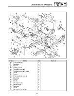
Страница 143: ... Shaft Bushing Collar Suspension wheel Collar Wheel bracket Front pivot arm bracket 2 2 4 2 1 2 1 2 1 2 1 4 2 2 2 2 2 Remove the parts in the order listed below A 4 Nm 0 4 mSkg 2 9 ftSlb 16 Nm 1 6 mSkg 12 ftSlb 24 Nm 2 4 mSkg 17 ftSlb 30 Nm 3 0 mSkg 22 ftSlb B C D 49 Nm 4 9 mSkg 35 ftSlb E 72 Nm 7 2 mSkg 52 ftSlb F ESSO beacon 325 grease or Aeroshell grease 7A 1 1 2 3 4 5 6 7 8 9 10 11 12 13 14 15...

Страница 144: ...lar Wheel bracket Circlip Suspension wheel Collar Bushing Shaft Rear suspension bracket Spacer Bushing Collar 2 2 2 2 2 2 2 1 1 2 2 1 A 24 Nm 2 4 mSkg 17 ftSlb 49 Nm 4 9 mSkg 35 ftSlb 72 Nm 7 2 mSkg 52 ftSlb B C ESSO beacon 325 grease or Aeroshell grease 7A 1 19 20 21 22 23 24 25 26 27 28 18 29 ...

Страница 145: ... Remarks Rear shock absorber Bushing Collar Pull rod Collar Bushing Guide wheel Control rod assembly Bushing Bushing 1 2 1 2 4 4 2 2 2 2 A 49 Nm 4 9 mSkg 35 ftSlb 72 Nm 7 2 mSkg 52 ftSlb B ESSO beacon 325 grease or Aeroshell grease 7A 1 30 31 32 33 34 35 36 37 38 39 ...

Страница 146: ...ear axle Guide wheel Collar Tension adjuster Collar Collar Sliding frame 1 2 1 1 1 1 2 2 1 1 3 2 2 1 1 2 For assembly reverse the disassembly procedure A 24 Nm 2 4 mSkg 17 ftSlb 72 Nm 7 2 mSkg 52 ftSlb 75 Nm 7 5 mSkg 54 ftSlb B C 40 41 42 43 44 45 46 47 48 49 50 51 52 53 ESSO beacon 325 grease or Aeroshell grease 7A 1 39 38 SLIDE RAIL SUSPENSION POWR TR ...

Страница 147: ...xle nut Tension adjuster Left side cover Slide rail suspension Collar 1 2 Remove the parts in the order listed below Loosen Loosen Refer to PRIMARY SHEAVE AND DRIVE VELT For installation reverse the removal procedure A 72 Nm 7 2 mSkg 52 ftSlb SLIDE RAIL SUSPENSION POWR TR RX10M RX10MS ...

Страница 148: ...ront suspension bracket Suspension wheel Collar Wheel bracket 2 2 2 1 1 4 2 1 1 2 1 4 2 1 2 2 2 Remove the parts in the order listed below A 4 Nm 0 4 mSkg 2 9 ftSlb 16 Nm 1 6 mSkg 12 ftSlb 24 Nm 2 4 mSkg 17 ftSlb 30 Nm 3 0 mSkg 22 ftSlb B C D 49 Nm 4 9 mSkg 35 ftSlb E 72 Nm 7 2 mSkg 52 ftSlb F ESSO beacon 325 grease or Aeroshell grease 7A 1 1 2 3 4 5 6 7 8 9 10 11 12 13 14 15 16 17 SLIDE RAIL SUSP...

Страница 149: ...clip Suspension wheel Collar Bushing Collar Rear suspension bracket Spacer Bushing Collar 2 2 2 2 2 2 2 2 1 1 2 2 1 A 24 Nm 2 4 mSkg 17 ftSlb 49 Nm 4 9 mSkg 35 ftSlb 72 Nm 7 2 mSkg 52 ftSlb B C ESSO beacon 325 grease or Aeroshell grease 7A 1 18 19 20 21 22 23 24 25 26 27 28 29 30 SLIDE RAIL SUSPENSION POWR TR ...

Страница 150: ... Collar Pull rod Collar Bushing Guide wheel Control rod assembly Bushing Bushing Shaft 1 2 1 2 4 4 2 2 2 2 1 A 49 Nm 4 9 mSkg 35 ftSlb 72 Nm 7 2 mSkg 52 ftSlb B ESSO beacon 325 grease or Aeroshell grease 7A 1 31 32 33 34 35 36 37 38 39 40 41 SLIDE RAIL SUSPENSION POWR TR ...

Страница 151: ...Rear axle Guide wheel Collar Tension adjuster Collar Collar Sliding frame 1 2 1 1 1 1 2 2 1 1 4 2 2 2 1 2 For assembly reverse the disassembly procedure A 24 Nm 2 4 mSkg 17 ftSlb 72 Nm 7 2 mSkg 52 ftSlb 75 Nm 7 5 mSkg 54 ftSlb B C ESSO beacon 325 grease or Aeroshell grease 7A 1 42 43 44 45 46 47 48 49 50 51 52 53 54 55 56 57 SLIDE RAIL SUSPENSION POWR TR ...

Страница 152: ...pect SStopper band 1 Frayed damage Replace SPull rod 2 Bends damage Replace SShock absorber 3 Oil leaks damage Replace SBushings Wear cracks damage Replace SFront pivot arm 4 SRear pivot arm 5 SRear pivot arm bracket 6 SSuspension wheel bracket 7 SSliding frame 8 Cracks damage Replace SSlide runner 9 Wear damage Replace A RX10 RX10S RX10R RX10RS B RX10M RX10MS ...

Страница 153: ...tall the stopper band with a toward the hook and b toward the front suspension bracket SFor RX10M RX10MS Install the stopper band with a toward the hook and b toward the shaft Nut stopper band 4 Nm 0 4 mSkg 2 9 ftSlb INSTALLATION 1 Adjust SSlide rail suspension position Refer to REAR SUSPENSION in CHAP TER 2 ...

Страница 154: ...2 5P 3 7 5 0 098P 3 0 295 RX10M RX10MS 257 5 10 14 165 0 6 50 0 098P 3 0 295 Control rod 1 parts number Control rod 2 parts number Washer plate parts number Washer plate thickness mm in parts number parts number Upper Lower 8FA 4745A 00 RX10 RX10S RX10R RX10RS 8CR 4745B 00 90202 16229 2 5 0 098 90202 16232 10 0 0 394 8EP 4745A 00 RX10M RX10MS 90202 16229 2 5 0 098 90202 16230 5 0 0 197 ...

Страница 155: ...r Gear unit Set bolt Front axle assembly Bearing Track 1 1 1 2 1 1 1 Remove the parts in the order listed below Refer to DRIVE CHAIN HOUSING Refer to SLIDE RAIL SUSPENSION Refer to SECONDARY SHEAVE For installation reverse the removal procedure A 9 Nm 0 9 mSkg 6 5 ftSlb 20 Nm 2 0 mSkg 14 ftSlb 40 Nm 4 0 mSkg 29 ftSlb B C FRONT AXLE AND TRACK POWR TR FRONT AXLE AND TRACK ...

Страница 156: ...1 Wear break damage Replace SFront axle 2 Bends scratches excessive damage Re place INSTALLATION 1 Install SSprocket wheels SGuide wheels SWhen pressing the sprocket wheels onto the front axle align the lugs on each sprocket wheel SPosition each sprocket wheel on the axle as shown in the illustration A RX10 RX10S RX10R RX10RS B RX10M RX10MS ...

Страница 157: ...D TRACK POWR TR A B NOTE 2 Place the track in the chassis For track with a direction of rotation mark a Install the track with the mark pointing in the direction of track rotation A RX10 RX10S RX10R RX10RS B RX10M RX10MS ...

Страница 158: ...nk removal Rear cover Muffler end pipe Muffler side cover Tail brake light cover Seat Fuel tank cover Side cover Fuel tank 1 2 2 1 1 1 2 1 Remove the parts in the order listed below For installation reverse the removal procedure SEAT AND FUEL TANK ENG ENGINE SEAT AND FUEL TANK ...

Страница 159: ...rotector Muffler Exhaust pipe Gasket Band 1 1 2 2 2 Remove the parts in the order listed below Refer to SLIDE RAIL SUSPENSION in CHAPTER 4 Refer to SEAT AND FUEL TANK For installation reverse the removal procedure Refer to FRONT AXLE AND TRACK in CHAPTER 4 A 20 Nm 2 0 mSkg 14 ftSlb 25 Nm 2 5 mSkg 18 ftSlb B 16 Nm 1 6 mSkg 12 ftSlb C 11 Nm 1 1 mSkg 8 ftSlb D EXHAUST PIPE AND MUFFLER ...

Страница 160: ...ang the exhaust pipe to the frame a 3 Tighten SExhaust pipe bolts 1 Bolt band 9 Nm 0 9 mSkg 7 ftSlb 4 Tighten SExhaust pipe bolts 1 SMuffler band bolts 2 Bolt exhaust pipe 25 Nm 2 5 mSkg 18 ftSlb Bolt muffler band 20 Nm 2 0 mSkg 14 ftSlb 5 Tighten SMuffler bolt 1 Bolt muffler 16 Nm 1 6 mSkg 12 ftSlb ...

Страница 161: ...rder listed below Refer to PRIMARY SHEAVE AND DRIVE V BELT in CHAPTER 4 Drain Refer to COOLING SYSTEM in CHAPTER 2 Refer to SEAT AND FUEL TANK Refer to STEERING in CHAPTER 3 Refer to A C MAGNETO AND STARTER CLUTCH For installation reverse the removal procedure Refer to CARBURETORS in CHAPTER 7 A 7 Nm 0 7 mSkg 5 1 ftSlb 65 Nm 6 5mSkg 47 ftSlb B 30 Nm 3 0 mSkg 22 ftSlb C 23 Nm 2 3 mSkg 17 ftSlb D EN...

Страница 162: ...ion steps STighten the rear engine mounting adjust bolt Bolt engine mounting adjust 7 Nm 0 7 mSkg 5 1 ftSlb STighten the rear engine mounting nut Nut engine mounting 65 Nm 6 5 mSkg 47 ftSlb STighten the front right and left engine mount ing adjust bolts until they come to cantact with the engine damper At this time do not apply torque to the engine mounting adjust bolts STighten the front right an...

Страница 163: ...Spark plug Cylinder head cover Cylinder head cover gasket Timing chain guide top side 4 4 1 1 1 Remove the parts in the order listed below Drain Refer to HEAT EXCHANGER in CHAPTER 6 For installation reverse the removal procedure A 12 Nm 1 2 mSkg 8 7 ftSlb 13 Nm 1 3 mSkg 9 4 ftSlb B CAMSHAFTS ENG CAMSHAFTS CYLINDER HEAD COVER ...

Страница 164: ...ke camshaft sprocket Exhaust camshaft sprocket Intake camshaft cap Dowel pin Exhaust camshaft cap 1 1 1 1 1 1 3 12 3 Remove the parts in the order listed below Refer to A C MAGNETO AND STARTER CLUTCH During removal the dowel pins may still be connected to the camshaft caps NOTE A 10 Nm 1 0 mSkg 7 2 ftSlb 24 Nm 2 4 mSkg 17 ftSlb B 6 Nm 0 6 mSkg 4 3 ftSlb C 10 Nm 1 0 mSkg 7 2 ftSlb D CAMSHAFTS ENG C...

Страница 165: ...ftSlb 24 Nm 2 4 mSkg 17 ftSlb B 6 Nm 0 6 mSkg 4 3 ftSlb C 10 Nm 1 0 mSkg 7 2 ftSlb D Order Job name Part name Q ty Remarks 10 11 Intake camshaft Exhaust camshaft 1 1 For installation reverse the removal procedure CAMSHAFTS ENG ...

Страница 166: ...ression stroke align the I mark a with the stationary pointer b on the A C magneto rotor STDC on the compression stroke can be found when the camshaft lobes are turned away from each other 3 Loosen SCamshaft sprocket bolts 1 4 Loosen STiming chain tensioner cap bolt 1 5 Remove STiming chain tensioner 2 SGasket 6 Remove SCamshaft sprockets 1 To prevent the timing chain from falling into the crankca...

Страница 167: ...e exhaust side 1 SCamshaft caps SDowel pins To prevent damage to the cylinder head camshafts or camshafts caps loosen the camshaft cap bolts in stages and in a criss cross pattern working from the outside in 8 Remove SIntake camshaft 1 SExhaust camshaft 2 ...

Страница 168: ...aft dimensions Intake Limit a 32 40 mm 1 2756 in b 24 85 mm 0 9783 in Exhaust Limit a 32 85 mm 1 2933 in b 24 85 mm 0 9783 in 3 Measure SCamshaft runout Out of specification Replace Camshaft runout 0 03 mm 0 0012 in 4 Measure SCamshaft journal to camshaft cap clear ance Out of specification Measure the cam shaft journal diameter Camshaft journal to camshaft cap clearance 0 028 X 0 062 mm 0 0011 X ...

Страница 169: ...stigauge Bolt camshaft cap 10 Nm 1 0 mSkg 7 2 ftSlb SRemove the camshaft caps and then mea sure the width of the Plastigauge 1 5 Measure SCamshaft journal diameter a Out of specification Replace the cam shaft Within specification Replace the cylinder head and the camshaft caps as a set Camshaft journal diameter 24 459 X 24 472 mm 0 9630 X 0 9635 in 6 Inspect SCamshaft sprocket More than 1 4 tooth ...

Страница 170: ...the tensioner rod fully clockwise with a thin screwdriver 1 SRemove the screwdriver and slowly release the timing chain tensioner rod SMake sure that the timing chain tensioner rod comes out of the timing chain tensioner hous ing smoothly If there is rough movement re place the timing chain tensioner 9 Inspect SAll parts Damage wear Replace the defective part s ...

Страница 171: ...ment Reinstall 3 Install SCamshaft cap bolts Bolt camshaft cap 10 Nm 1 0 mSkg 7 2 ftSlb Tighten the camshaft cap bolts in stages and in a crisscross pattern working from the inner caps out The camshaft cap bolts must be tightened evenly or damage to the cylinder head cam shaft caps and camshafts will result 4 Install SIntake camshaft sprocket SExhaust camshaft sprocket Installation steps STurn the...

Страница 172: ...osite each other so that the punch marks c in the camshaft are aligned with the arrow marks d in the cam shaft caps as shown SWhile holding the camshafts temporarily tight en the camshaft sprocket bolts 5 Install STiming chain tensioner Installation steps SWhile lightly pressing the timing chain tension er rod by hand turn the tensioner rod fully clockwise with a thin screwdriver 1 SWith the timin...

Страница 173: ...cap 6 Nm 0 6 mSkg 4 3 ftSlb STurn the crankshaft several turns clockwise 6 Inspect Inspection steps S I mark a Make sure that the I mark on the A C magne to rotor is aligned with the stationery pointer b on the A C magneto rotor cover SCamshaft punch marks c Make sure that the punch marks c on the camshaft are aligned with the arrow mark d on the camshaft caps Out of alignment Adjust Refer to the ...

Страница 174: ...d Gasket Cylinder head Cylinder head gasket Dowel pin 1 4 1 4 4 1 1 2 Remove the parts in the order listed below Refer to SEAT AND FUEL TANK Refer to CAMSHAFTS For installation reverse the removal procedure A 20 Nm 2 0 mSkg 14 ftSlb 121_ 20 Nm 2 0 mSkg 14 ftSlb 105_ B 20 Nm 2 0 mSkg 14 ftSlb 140_ C 12 Nm 1 2 mSkg 8 7 ftSlb D 25 Nm 2 5 mSkg 18 ftSlb E CYLINDER HEAD ENG CYLINDER HEAD ...

Страница 175: ...REMOVAL 1 Remove SCylinder head nuts 1 SCylinder head cap nut 2 SCylinder head bolts 3 SLoosen the nuts in the proper sequence as shown SLoosen each nut 1 2 of a turn at a time After all of the nuts are fully loosened remove them ...

Страница 176: ...deposits rust Eliminate 3 Measure SCylinder head warpage Out of specification Resurface the cylin der head Warpage limit 0 1 mm 0 004 in Measurement steps SPlace a straightedge 1 and a thickness gauge 2 across the cylinder head SMeasure the warpage SIf the limited is exceeded resurface the cylin der head as follows SPlace a 400 X 600 grit wet sandpaper on the surface plate and resurface the cylind...

Страница 177: ...etighten the nuts to specification torque Tightening steps STighten the nuts 1 2 Nut cylinder head 1st 20 Nm 2 0 mSkg 14 ftSlb 2nd 121_ STighten the nuts 3 X 6 8 9 Nut cylinder head 1st 20 Nm 2 0 mSkg 14 ftSlb 2nd 105_ STighten the nuts 7 10 Nut cylinder head 1st 20 Nm 2 0 mSkg 14 ftSlb 2nd 140_ SCylinder head bolts 11 12 Bolt cylinder head 12 Nm 1 2 mSkg 8 7 ftSlb SApply engine oil onto the threa...

Страница 178: ...e cotter Intake valve retainer Intake valve spring Intake valve stem seal Intake valve spring seat Intake valve Intake valve guide Exhaust valve lifter Exhaust valve pad Exhaust valve cotter Exhaust valve retainer 12 12 24 12 12 12 12 12 12 8 8 16 8 Remove the parts in the order listed below Refer to CYLINDER HEAD VALVES AND VALVE SPRINGS ENG VALVES AND VALVE SPRINGS ...

Страница 179: ...t name Q ty Remarks 14 15 16 17 18 Exhaust valve spring Exhaust valve stem seal Exhaust valve spring seat Exhaust valve Exhaust valve guide 8 8 8 8 8 For installation reverse the removal procedure VALVES AND VALVE SPRINGS ENG ...

Страница 180: ...lifter and valve pad so that they can be reinstalled in their original place 2 Inspect SValve sealing Leakage at the valve seat Inspect the valve face valve seat and valve seat width Inspection steps SPour a clean solvent a into the intake and ex haust ports SCheck that the valves properly seal There should be to leakage at the valve seat 1 3 Remove SValve cotters 1 Remove the valve cotters by com...

Страница 181: ...ery carefully so that it can be reinstalled in its original place INSPECTION 1 Measure SValve stem to valve guide clearance Valve stem to valve guide clearance Valve guide inside diameter Valve stem diameter Out of specification Replace the valve guide Valve stem to valve guide clearance Intake 0 010 X 0 037 mm 0 0004 X 0 0015 in Exhaust 0 025 X 0 052 mm 0 0010 X 0 0020 in 2 Replace SValve guide T...

Страница 182: ...ve guide remover Intake ø4 90890 04111 YM 04111 Exhaust ø4 5 90890 04116 YM 04116 Valve guide installer Intake ø4 90890 04112 YM 04112 Exhaust ø4 5 90890 04117 YM 04117 Valve guide reamer Intake 90890 04113 YM 04113 Exhaust 90890 04118 YM 04118 3 Eliminate SCarbon deposits from the valve face and valve seat 4 Inspect SValve face Pitting wear Grind the valve face SValve stem end Mushroom shape or d...

Страница 183: ...width a Out of specification Replace the cylinder head Valve seat width Intake 0 9 X 1 1 mm 0 035 X 0 043 in Exhaust 0 9 X 1 1 mm 0 035 X 0 043 in Measurement steps SApply Mechanic s blueing dye Dykem 1 onto the valve face SInstall the valve into the cylinder head SPress the valve through the valve guide and onto the valve seat to make a clear pattern SMeasure the valve seat width Where the valve ...

Страница 184: ...e back and forth be tween your hand SApply a fine lapping compound to the valve face and repeat the above steps SAfter every lapping procedure be sure to clean off all of the lapping compound from the valve face and valve seat SApply Mechanic s blueing dye Dykem onto the valve face SInstall the valve into the cylinder head SPress the valve through the valve guide and onto the valve seat to make a ...

Страница 185: ... at 34 5 mm 8 2 X 9 6 kg at 34 5 mm 18 1 X 21 2 lb at 1 36 in Exhaust 110 X 126 N at 35 0 mm 11 0 X 12 6 kg at 35 0 mm 24 3 X 27 8 lb at 1 38 in 13 Measure SValve spring tilt a Out of specification Replace the valve spring Spring tilt Intake 2 5_ 1 7 mm 0 067 in Exhaust 2 5_ 1 8 mm 0 071 in 14 Inspect SValve lifter Damage scratches Replace the valve lift ers and cylinder head ...

Страница 186: ...ant Molybdenum disulfide oil 3 Install SValve 1 SLower spring seat 2 SOil seal 3 SValve spring 4 SUpper spring seat 5 into the cylinder head Install the valve spring with the larger pitch a facing up Smaller pitch b Make sure that each valve is installed in its origi nal place Refer to the following embossed marks Right and left intake valve s 4XV Middle intake valve s 4XV Exhaust valve s 5LV ...

Страница 187: ... 04114 YM 4114 Exhaust valve 90890 04108 YM 4108 5 To secure the valve cotters onto the valve stem lightly tap the valve tip with a soft face hammer Hitting the valve tip with excessive force could damage the valve 6 Install SValve pad 1 SValve lifter 2 SApply molybdenum disulfide oil onto the valve lifter and valve pad SThe valve lifter must move smoothly when ro tated with a finger SEach valve l...

Страница 188: ...wel pin 1 1 1 1 2 Remove the parts in the order listed below Refer to DRIVE CHAIN HOUSING in CHAPTER 4 Drain Refer to ENGINE OIL REPLACEMENT in CHAPTER 2 Disconnect For installation reverse the removal procedure A 12 Nm 1 2 mSkg 8 7 ftSlb 10 Nm 1 0 mSkg 7 2 ftSlb B 19 Nm 1 9 mSkg 14 ftSlb C A C MAGNETO AND STARTER CLUTCH ENG A C MAGNETO AND STARTER CLUTCH A C MAGNETO ROTOR COVER ...

Страница 189: ...r Idle gear shaft Starter motor idle gear Starter clutch Woodruff key Starter clutch gear 1 1 1 1 1 1 Remove the parts in the order listed below For installation reverse the removal procedure A 130 Nm 13 0 mSkg 94 ftSlb 12 Nm 1 2 mSkg 8 7 ftSlb B A C MAGNETO AND STARTER CLUTCH ENG A C MAGNETO ROTOR AND STARTER CLUTCH ...

Страница 190: ...C magneto rotor Sheave holder 90890 01701 YS 01880 2 Remove SA C magneto rotor 1 with the rotor holding puller 2 and rotor holding puller attachment SWoodruff key To protect the end of the crankshaft place an appropriate sized socket between the ro tor holding puller set s center bolt and the crankshaft Make sure the rotor holding puller is centered over the A C magneto rotor Rotor holding puller ...

Страница 191: ... roughness wear Replace the defective part s SStarter clutch gear s contacting surfaces a Damage pitting wear Replace the starter clutch gear 6 Inspection SStarter clutch operation Installation steps SInstall the starter clutch gear 1 onto the start er clutch 2 and hold the starter clutch SWhen turning the starter clutch gear clockwise A the starter clutch and the starter clutch gear should engage...

Страница 192: ...1 2 mSkg 8 7 ftSlb LOCTITER 3 Install SWoodruff key SMagneto rotor SWasher SBolt SClean the tapered portion of the crankshaft and the magneto rotor hub SWhen installing the magneto rotor make sure the woodruff key is properly seated in the key way of the crankshaft 4 Tighten SBolt 1 Bolt A C magneto rotor 130 Nm 13 0 mSkg 94 0 ftSlb SWhile holding the A C magneto rotor 2 with the sheave holder 3 t...

Страница 193: ...5 36 A C MAGNETO AND STARTER CLUTCH ENG 5 Apply SSealant onto the stator coil assembly lead grommet Yamaha bond No 1215 90890 85505 Quick gasket ACC 1100 15 01 ...

Страница 194: ... Oil pan Gasket Dowel pin Oil pump assembly Oil pipe 1 1 1 4 1 1 Remove the parts in the order listed below Refer to ENGINE ASSEMBLY Refer to WATER PUMP in CHAPTER 6 For installation reverse the removal procedure A 10 Nm 1 0 mSkg 7 2 ftSlb 12 Nm 1 2 mSkg 8 7 ftSlb B OIL PAN AND OIL PUMP ENG OIL PAN AND OIL PUMP ...

Страница 195: ...n Oil pump outer rotor 1 Oil pump cover 2 Oil pump inner rotor 2 Oil pump outer rotor 2 Oil pump shaft Valve Spring Pin Oil pump housing 1 1 2 1 1 1 1 1 1 1 4 1 Disassemble the parts in the order listed below For assembly reverse the disassembly procedure 1 2 3 4 5 6 7 8 9 10 11 12 OIL PAN AND OIL PUMP ENG ...

Страница 196: ...IL PAN AND OIL PUMP ENG NOTE REMOVAL 1 Remove SPipe 1 SOil pan 2 SOil pump Loosen each bolt 1 4 of a turn at a time in stages and in a crisscross pattern After all of the bolts are fully loosened remove them ...

Страница 197: ...e b between outer rotor 2 and pump housing 3 Out of specifications Replace oil pump as sembly Inner rotor to outer rotor tip clearance 0 09 X 0 15 mm 0 004 X 0 006 in Outer rotor to oil pump housing clearance 0 03 X 0 08 mm 0 001 X 0 003 in 3 Inspect SCheck ball seat 1 SCheck ball 2 SSpring 3 SValve 4 Damage wear Replace the defective part s 4 Inspect SPipe 1 SOil strainer 2 Damage Replace Obstruc...

Страница 198: ...er rotor 3 SHousing 4 When installing the inner rotor align the pin 1 in the oil pump shaft with the groove a on the inner rotor 2 3 Inspect SOil pump operation Unsmooth operation Replace 4 Install SOil pump assembly 1 SOil strainer 2 SPipe 3 5 Install SDowel pin SGasket SOil pan 6 Tighten SOil pan bolts Bolt oil pan 10 Nm 1 0 mSkg 7 2 ftSlb Tighten the oil pan bolts in stages and in a criss cross...

Страница 199: ...e intake side Lower crankcase Dowel pin Counter shaft oil seal Cover 1 2 1 1 1 1 1 2 1 1 Remove the parts in the order listed below For installation reverse the removal procedure A 12 Nm 1 2 mSkg 8 7 ftSlb 15 Nm 1 5 mSkg 11 ftSlb B 12 Nm 1 2 mSkg 8 7 ftSlb C 10 Nm 1 0 mSkg 7 2 ftSlb D CRANKCASE ENG CRANKCASE CRANKCASE E Tighten these bolts first F Tighten these bolts second ...

Страница 200: ...val Connecting rod cap Big end bearing Piston pin clip Piston pin Piston Connecting rod Top ring 2nd ring Oil ring 4 8 8 4 4 4 4 4 4 Remove the parts in the order listed below For installation reverse the removal procedure A 20 Nm 2 0 mSkg 14 ftSlb 120_ CRANKCASE ENG CONNECTING RODS AND PISTONS ...

Страница 201: ...ft assembly Oil pump drive chain Oil pump driven gear Order Job name Part name Q ty Remarks 1 2 3 4 5 6 7 1 10 1 1 1 1 1 Remove the parts in the order listed below For installation reverse the removal procedure A 75 Nm 7 5 mSkg 54 ftSlb CRANKCASE ENG CRANKSHAFT AND COUNTER SHAFT A This bolt has a left hand thread ...

Страница 202: ...nkcase tightening sequence 2 Remove SLower crankcase Tap on one side of the crankcase with a soft face hammer Tap only on reinforced por tions of the crankcase not on the crankcase mating surfaces Work slowly and carefully and make sure that the crankcase halves separate evenly 3 Remove SDowel pins SCrankshaft journal bearing Identify the position of each crankshaft journal lower bearing so that i...

Страница 203: ...ve and the piston s pin bore area If both areas are deburred and the piston pin is still difficult to remove remove it with the piston pin puller 1 Piston pin puller 90890 01304 YU 01304 6 Remove STop ring S2nd ring SOil ring When removing a piston ring open the end gap with your fingers and lift the other side of the ring over the piston crown 7 Remove SCrankshaft SCrankshaft journal bearing Iden...

Страница 204: ...gauge 1 Measure cylinder bore C by taking side to side and front to back measurements of the cylinder Then find the average of the measure ments Cylinder bore C 74 000 X 74 010 mm 2 9134 X 2 9138 in Wear limit 74 06 mm 2 9157 in Taper limit T 0 05 mm 0 0020 in Out of round R 0 05 mm 0 0020 in C maximum of D1 X D6 T maximum of D1 or D2 maximum of D5 or D6 R maximum of D1 D3 or D5 maximum of D2 D4 o...

Страница 205: ...ance Cylinder bore C Piston skirt diameter P Piston to cylinder clearance 0 030 X 0 055 mm 0 0012 X 0 0022 in Limit 0 12 mm 0 0047 in SIf out of specification replace the cylinder and the piston and piston rings as a set 3 Measure SSide clearance piston rings Use the thickness gauge 1 Out of specification Replace the piston and piston rings as a set Eliminate the carbon deposits from the piston ri...

Страница 206: ...measured If the oil ring rail s gap is exces sive replace all three piston rings Piston ring end gap Top ring 0 32 X 0 44 mm 0 010 X 0 020 in 2nd ring 0 43 X 0 58 mm 0 017 X 0 023 in Oil ring 0 10 X 0 35 mm 0 004 X 0 014 in 6 Inspect SPiston pin Blue discoloration grooves Replace the piston pin and then check the lubrication sys tem 7 Measure SOutside diameter piston pin Out of specification Repla...

Страница 207: ...ce Out of specification Replace the piston pin and piston as a set Piston pin to piston pin bore clearance Piston pin bore size Piston pin outside diameter Piston pin to piston pin bore clearance 0 002 X 0 022 mm 0 00008 X 0 0009 in Limit 0 072 mm 0 0028 in 10 Measure SRunout Use the V blocks and a dial gauge Out of specification Replace the crank shaft Dial gauge 90890 03097 YU 03097 Crankshaft r...

Страница 208: ...o obtain the correct crankshaft journal to crankshaft journal bearing clear ance and prevent engine damage the crank shaft journal bearings must be installed in their original positions SClean the crankshaft journal bearings crank shaft journals and bearing portions of the crankcase SPlace the upper crankcase upside down on a bench SInstall the crankshaft journal upper bearings 1 and the crankshaf...

Страница 209: ...cast on the crankcase Crankcase bolt Bolt 1 X 10 1st 15 Nm 1 5 mSkg 11 ftSlb 2nd 15 Nm 1 5 mSkg 11 ftSlb 45 X 50_ Bolt 11 X 26 12Nm 1 2 mSkg 8 7 ftSlb M9 105 mm bolts 1 X 10 M8 65 mm bolts 16 20 M5 90 mm bolts 26 M5 80 mm bolts 25 M5 55 mm bolts 11 X 15 M5 45 mm bolts 17 19 21 X 24 M5 25 mm bolts 18 Lubricate the crankcase bolt threads with en gine oil SRemove the lower crankcase and the crank sha...

Страница 210: ...e the same use the same size for all of the bearings Selection of bearings For example if the crankcase J1 and crank shaft web J1 numbers are 6 and 2 respec tively then the bearing size for J1 is Bearing size for J1 J1 crankcase J1 crankshaft web 2 6 2 2 2 black CRANKSHAFT JOURNAL BEARING COLOR CODE 1 Violet 0 White 1 Blue 2 Black 3 Brown 14 Measure SCrankshaft pin to big end bearing clear ance Ou...

Страница 211: ... connecting rod cap Align the projections a on the big end bearings with the notches b in the connecting rod and connecting rod cap SPut a piece of Plastigauge 1 on the crank shaft pin SAssemble the connecting rod halves SDo not move the connecting rod or crankshaft until the clearance measurement has been completed SApply molybdenum disulfide grease onto the bolts threads and nut seats SMake sure...

Страница 212: ...rther to reach the specified angle 120_ When the nut is tightened more than the specified angle do not loosen the nut and then retighten it Replace the bolt with a new one and perform the procedure again SDo not use a torque wrench to tighten the nut to the specified angle STighten the nut until it is at the specified angles When using a hexagonal nut note that the angle from one corner to another...

Страница 213: ...ngs For example if the connecting rod P1 and the crankshaft web P1 numbers are 5 and 1 re spectively then the bearing size for P1 is Bearing size for P1 P1 connecting rod P1 crankshaft 2 5 1 2 2 Black BIG END BEARING COLOR CODE 1 Violet 0 White 1 Blue 2 Black 3 Brown 16 Inspect SCrankcase Cracks damage Replace Thoroughly wash the crankcase halves in a mild solvent Thoroughly clean all the gasket s...

Страница 214: ...age wear Replace 19 Inspect SPrimary drive gear 1 SOil pump driven gear 2 Cracks damage wear Replace the de fective part s 20 Inspect STiming chain 1 SOil pump drive chain 2 Damage stiffness Replace the chain and sprocket as a set 21 Inspect STiming chain guide intake side Damage wear Replace the timing chain guide 22 Inspect SCounter shaft assembly Damage Replace ...

Страница 215: ...1 S2nd ring 2 SUpper oil ring rail 3 SOil ring expander 4 SLower oil ring rail 5 Be sure to install the piston rings so that the manufacturer s marks or numbers a face up 4 Install SPiston 1 onto the respective connecting rod 2 SPiston pin 3 SPiston pin clip New 4 SApply engine oil onto the piston pin SMake sure that the Y mark a on the connect ing rod faces left when the arrow mark b on the pisto...

Страница 216: ...nto the crankshaft pin SConnecting rod cap onto the connecting rod SAlign the projections on the big end bearings with the notches in the connecting rods and connecting rod caps SBe sure to reinstall each big end bearing in its original place SWhile compressing the piston rings with one hand install the connecting rod assembly into the cylinder with the other hand SMake sure that the Y marks a on ...

Страница 217: ...ecting rod bolts and nuts STighten the connecting rod nuts SPut a mark 1 on the corner of the connecting rod nut 2 and the connecting rod 3 STighten the nut further to reach the specified angle 120_ When the nut is tightened more than the specified angle do not loosen the nut and then retighten it Replace the bolt with a new one and perform the procedure again SDo not use a torque wrench to tighte...

Страница 218: ... sealant to come into contact with the oil gallery or crankshaft journal bear ings Do not apply sealant to within 2 X 3 mm of the crankshaft journal bearings 12 Install SCrankcase journal bearings 1 into the lower crankcase SAlign the projections a on the crankshaft jour nal lower bearings with the notches b in the crankcase SInstall each crankshaft journal lower bearing in its original place 13 I...

Страница 219: ... Nm 1 5 mSkg 11 ftSlb 2nd 15 Nm 1 5 mSkg 11 ftSlb 45 X 50_ Bolt 11 X 26 12 Nm 1 2 mSkg 8 7 ftSlb M9 105 mm bolts 1 X 10 M8 65 mm bolts 16 20 M5 90 mm bolts 26 M5 80 mm bolts 25 M5 55 mm bolts 11 X 15 M5 45 mm bolts 17 19 21 X 24 M5 25 mm bolts 18 15 Install SCounter shaft assembly STiming chain SOil pump drive chain 16 Install SGasket SCounter shaft cover SBolts Bolts countershaft cover 12 Nm 1 2 ...

Страница 220: ...er right Coolant hose 2 Heat exchanger rear Coolant hose 3 Heat exchanger left Coolant hose 4 Heat exchanger front Coolant hose 5 Water pump assembly Coolant hose 6 Coolant pipe 1 1 1 1 1 1 1 1 1 1 1 1 1 1 Remove the parts in the order listed below Drain Refer to COOLING SYSTEM in CHAPTER 2 Refer to PRIMARY SHEAVE AND DRIVE V VELT in CHAPTER 4 A 35 Nm 3 5 mSkg 25 ftSlb COOLING SYSTEM HEAT EXCHANGE...

Страница 221: ...Thermostat assembly Coolant hose 9 Coolant hose 10 Oil cooler outlet hose Oil cooler Oil cooler inlet hose Pipe 3 Water pump hose Carburetor heater hose Heat exchanger hose O ring Coolant hose 11 Coolant hose 12 1 1 2 1 1 1 1 1 1 1 1 1 1 1 1 1 For installation reverse the removal procedure A 35 Nm 3 5 mSkg 25 ftSlb HEAT EXCHANGER COOL ...

Страница 222: ...ens with a pressure below the speci fied pressure Replace Filler cap opening pressure 95 X 125 kPa 0 95 X 1 25 kg cm2 14 X 18 psi Measurement steps SAttach the cooling system tester 1 to the cool ant filler cap 2 Cooling system tester 90890 01325 YU 24460 01 Adapter 90890 01352 YU 33984 SApply the specified pressure for 10 seconds and make sure there is no pressure drop ...

Страница 223: ...oil cooler bolt Bolt oil cooler 35 Nm 3 5 mSkg 25 ftSlb SBefore installing the oil cooler lubricate the oil cooler bolt and O ring with a thin coat of engine oil SMake sure the O ring is positioned properly SAlign the projection a on the oil cooler with the slot b in the crankcase SBend the lock washer tab along a flat side of the bolt ...

Страница 224: ...ermostat housing cover Thermostat Thermostat housing Water temperature sensor 1 1 1 1 Disassemble the parts in the order listed below For assembly reverse the disassembly procedure 1 2 3 4 A 10 Nm 1 0 mSkg 7 2 ftSlb 23 Nm 2 3 mSkg 17 ftSlb B THERMOSTAT COOL THERMOSTAT ...

Страница 225: ...mometer in the water SWhile stirring the water observe the thermo stat and thermometer s indicated tempera ture 1 Thermometer 2 Water 3 Thermostat 4 Container A Fully closed B Fully open C More than 7 mm 0 276 in If the accuracy of the thermostat is in doubt re place it A faulty thermostat could cause serious overheating or overcooling 2 Inspect SThermostat housing cover SThermostat housing Cracks...

Страница 226: ...e b on the thermostat housing 2 Install SThermostat cover SBolts thermostat housing Bolt thermostat housing 10 Nm 1 0 mSkg 7 2 ftSlb 3 Install SWater temperature sensor 1 to the thermostat housing Water temperature sensor 23 Nm 2 3 mSkg 17 ftSlb Use extreme care when handling the water temperature sensor Replace any part that was dropped or subjected to a strong im pact ...

Страница 227: ...lip Impeller shaft Water pump seal Oil seal Bearing O ring Water pump housing Pipe 1 1 1 1 1 1 1 2 1 2 Disassembly the parts in the order listed below Refer to OIL PAN AND OIL PUMP For assembly reverse the disassembly procedure 1 2 3 4 5 6 7 8 9 10 A 12 Nm 1 2 mSkg 8 7 ftSlb WATER PUMP COOL WATER PUMP ...

Страница 228: ...pump seal 1 from the inside of the water pump housing 2 2 Remove SBearing 1 SOil seal 2 Remove the bearing 1 and oil seal 2 from the inside of the water pump housing 3 3 Remove SRubber damper holder 1 SRubber damper 2 from the impeller with a thin flat head screwdriver Do not scratch the impeller shaft ...

Страница 229: ...ect SBearing Rough movement Replace ASSEMBLY 1 Install SOil seal New 1 to the water pump housing SBefore installing the oil seal apply tap water or coolant onto its outer surface SInstall the oil seal with a socket that matches its outside diameter 2 Install SBearing Install the bearing with a socket that matches its outside diameter 3 Install SWater pump seal New Never apply oil or grease onto th...

Страница 230: ...g driver 90890 04058 YM 4058 Yamaha bond No 1215 90890 85505 ACC 11001 05 01 A Push down 4 Install SRubber damper holder 1 SRubber damper 2 Before installing the rubber damper apply tap water or coolant onto its outer surface 5 Measure Simpeller shaft tilt Out of specification Repeat steps 4 and 5 Make sure the rubber damper and rubber damper holder are flush with the impeller Max impeller shaft t...

Страница 231: ...Throttle position sensor coupler Carburetor heater lead Carburetor heating hose Fuel hose Throttle cable Carburetor assembly Caburetor joint Collar 1 1 2 1 1 1 2 2 1 1 4 4 Remove the parts in the order listed below Disconnect Disconnect Disconnect For installation reverse the removal procedure A 10 Nm 1 0 mSkg 7 2 ftSlb CARBURETORS CARB CARBURETION CARBURETORS ...

Страница 232: ...se Starter plunger link Connecting bolt Spacer Fuel inlet pipe Spring Vacuum chamber air vent hose Float chamber air vent hose Throttle position sensor Carburetor 1 3 1 2 3 2 1 2 2 1 4 Remove the parts in the order listed below For installation reverse the removal procedure 1 2 3 4 5 6 7 8 9 10 11 CARBURETORS CARB ...

Страница 233: ...t Vacuum chamber cover Piston valve spring Piston valve Jet needle holder Jet needle kit Pilot screw Fuel drain bolt Float pin 1 1 1 1 1 1 1 1 1 1 Disassemble the parts in the order listed below The following procedure applies to all of the carburetors NOTE 1 2 3 4 5 6 7 8 9 10 CARBURETORS CARB ...

Страница 234: ...t Needle valve Needle valve seat Main jet Main jet holder Pilot jet Needle jet Carburetor switch T O R S Carburetor heater Starter jet 1 1 1 1 1 1 1 1 1 1 For assembly reverse the disassembly procedure 11 12 13 14 15 16 17 18 19 20 CARBURETORS CARB ...

Страница 235: ... out all passage and jets with compressed air 3 Inspect SFloat chamber body 1 4 Inspect SFloat chamber rubber gasket 2 Cracks damage wear Replace 5 Inspect SFloat 1 Damage Replace 6 Inspect SNeedle valve 1 SNeedle valve seat 2 Damage obstruction wear Replace the needle valve needle valve seat and O ring as a set 7 Inspect SO ring 3 Damage wear Replace the needle valve needle valve seat and O ring ...

Страница 236: ...ilot screw 6 SNeedle jet 7 SPilot air jet 8 Bends damage wear Replace Obstruction Clean Blow out the jets with compressed air 11 Inspect SPiston valve movement Insert the piston valve into the carburetor body and move it up and down Tightness Replace the piston valve 12 Inspect SFuel feed pipes SHose joint Cracks damage Replace Obstruction Clean Blow out the pipes with compressed air 13 Inspect SF...

Страница 237: ...Out of specification Adjust Float height 11 X 15 mm 0 43 X 0 59 in Measurement and adjustment steps SHold the carburetor upside down SMeasure the distance between the carbure tor body and top of the floats The float arm should resting on the needle valve without exerting pressure on it SIf the float height is not within specification inspect the valve seat and needle valve SIf either is worn repla...

Страница 238: ...d and hose routing 1 Adjust SCarburetor synchronization Refer to SYNCHRONIZING THE CARBU RETORS in CHAPTER 2 2 Adjust SEngine idling speed Engine idle speed 1 350 100 r min 1 250 X 1 450 r min Refer to ENGINE IDLE SPEED ADJUST MENT in CHAPTER 2 3 Adjust SThrottle cable free play Refer to THROTTLE CABLE FREE PLAY in CHAPTER 2 ...

Страница 239: ... SLoosen the fuel drain screw SHold the fuel level gauge vertically next to the line on the float chamber SMeasure the fuel level a on both sides of the carburetor assembly The fuel level readings should be equal on both sides 2 Adjust SFuel level Adjustment steps SRemove the carburetor assembly SInspect the needle valve seat and needle valve SIf either is worn replace them as a set SIf both are f...

Страница 240: ...ue terminal 1 Tester lead Black terminal 2 SCheck the throttle position sensor resistance Throttle position sensor resistance R1 4 X 6 kΩ at 20_C 68_F Blue Black Out of specification Replace the throttle posi tion sensor SConnect the pocket tester Ω 1k to the throttle position sensor coupler Tester lead Yellow 3 Tester lead Black 2 SWhile slowly pushing the throttle check the throttle position sen...

Страница 241: ...tal multimeter lead 3 SMeasure the voltage A When measuring the voltage A be sure that the test coupler is connected to the throttle position sensor SCalculate the specified voltage B Specified voltage B Voltage A 0 136 SLoosen the throttle position sensor bolts 4 SConnect the digital multimeter to the test cou pler Digital multimeter lead 1 Digital multimeter lead 3 SAdjust the throttle position ...

Страница 242: ...ty vac 1 to the vacuum hose 2 Mity vac 90890 06756 YB 35956 SPlace a container 3 under the end of the fuel hoses 4 SOperate the Mity vac 1 while checking that fuel flows from the fuel hoses 4 SIf fuel does not flow out replace the fuel pump INSTALLATION After installing all parts refer to CABLE ROUT ING in CHAPTER 9 to check the cable lead and hose routings ...

Страница 243: ...h turn it on and off a few times INSPECTING A SWITCH SHOWN IN THE MANUAL The terminal connections for switches main switch handlebar switch engine stop switch light switch etc are shown in a chart similar to the one on the left This chart shows the switch positions in the col umn and the switch lead colors in the top row For each switch position indicates the terminals with continuity The example ...

Страница 244: ... Br RUN STOP OFF OPEN RUN IDLE Br W B Y B L B W W G W R Br W B Y B W Br W Br Y Y B G R Sb Y G Lg G Y R Lg G B L O Gy W Y B R L R B W L W Y Y W Y L Lg W Lg L B L W R B L Y L L R Lg W G G R Br Y Y B Lg G Y G B W B W G B Y Y W W Y L Lg L Br W Lg Y R Sb Br W B R B W Y W Gy O B Lg B W Lg Y R B B B B R B R O O B R Gy B R W B R Y B R Gy B R W B R Y Y L Y W B L Y L Y W B L L W Y B L L Y B Y W B L W L L B ...

Страница 245: ... magneto 2 Rectifier regulator 3 Main switch 4 Main relay 5 Fuse MAIN 8 Battery 9 Engine stop switch 10 Throttle switch 11 Carburetor switch 16 CDI unit 17 ignition coil 18 Spark plug 31 Fuse IGNITION IGNITION SYSTEM CIRCUIT DIAGRAM ...

Страница 246: ...IFICATION Replace the stator coil assembly Check the spark plug gap OUT OF SPECIFICATION Repair or replace the spark plug Check the ignition coil resistance OUT OF SPECIFICATION Replace the ignition coil Check the engine stop switch throttle switch carburetor switch and main switch FAULTY Replace the handlebar switch right carburetor switch and or main switch Check the main relay FAULTY Replace th...

Страница 247: ...re SStator coil resistance b pickup coil resis tance a Out of specification Replace Pickup coil resistance Gray Black 189 X 231 Ω at 20_C 68_F Stator coil resistance White White 0 19 X 0 24 Ω at 20_C 68_F SPARK PLUG 1 Remove SSpark plugs 2 Measure SSpark plug gap a Standard spark plug CR9E NGK Spark plug gap 0 7 X 0 8 mm 0 028 X 0 031 in ...

Страница 248: ... the spark plug SConnect the dinamic spark tester 1 SSet the main switch to ON SMeasure the ignition spark gap a Spark gap 6 mm 0 24 in IGNITION COIL 1 Disconnect SIgnition coil lead 2 Connect SPocket tester 3 Measure SPrimary coil resistance a SSecondary coil resistance b Out of specification Replace Primary coil resistance 0 16 X 0 22 Ω at 20_C 68_F Secondary coil resistance 5 0 X 6 8 kΩ at 20_C...

Страница 249: ... fails to return to idle when the lever is released SIf T O R S operates make sure that the cause of the malfunction is corrected and that the engine can be operated without a problem before restarting the engine SBe sure to use the standard resistance type spark plug and spark plug cap Other wise T O R S will not work properly Idling or starting Running Trouble Throttle switch OFF ON OFF Carburet...

Страница 250: ...inuity RUN pulled out Yes OFF pushed in No 4 Inspect SThrottle switch continuity Faulty Replace the handlebar switch right Throttle switch position Continuity Throttle lever is operated Yes Throttle lever is not operated No CARBURETOR SWITCH 1 Disconnect SCarburetor switch lead 1 2 Connect SPocket tester 3 Inspect SCarburetor switch continuity Faulty Replace Carburetor switch position Continuity T...

Страница 251: ... R W OFF ON START Continuity MAIN RELAY 1 Inspect SMain relay 1 Inspection steps SDisconnect the main relay from the coupler SConnect the pocket tester Ω 1 and bat tery 12 V to the main relay terminals as shown Positive battery terminal Brown 1 Negative battery terminal Brown White 2 Positive tester probe Red 3 Negative tester probe Blue 4 SIf main relay does not have continulty be tween the red a...

Страница 252: ... Br R Br W R W R Y R L Br W Br R W B Y Br Y L R Br W L R L R W B R R R B B B B L R W B Y B Y B B B Y B Y B Br Y R W L R Br RUN STOP OFF OPEN Br W B Y B L W B W R B R 1 2 3 4 5 9 10 12 6 7 8 28 29 30 31 ELECTRICAL STARTING SYSTEM CIRCUIT DIAGRAM Main switch Fuse MAIN Starter relay Starter motor Battery Engine stop switch Fuse IGNITION 3 5 6 7 8 9 31 ...

Страница 253: ...onnect SStarter relay coupler terminals Jumper lead 5 Inspect SStarter motor operation Replace the starter relay NO OK 1 NO Charge and or replace the battery Refer to BATTERY INSPEC TION in CHAPTER 2 Repair or replace the starter motor OK WARNING A wire for the jumper lead must have the equivalent capacity as that of the battery lead or more otherwise it may cause the jumper lead to be burned This...

Страница 254: ...nd or ignition fuse FAULTY Check the main switch OK Correct the connection OK Replace the main switch FAULTY MAIN SWITCH 1 Disconnect SMain switch coupler 1 2 Connect SPocket tester 3 Inspect SMain switch continuity Faulty Replace Switch position Continuity OFF Yes ON No Switch Color code position Br R Y Br W R W OFF ON START Continuity ...

Страница 255: ...or yoke O ring Armature assembly Brush Brush holder Starter motor front cover Bearing 1 1 1 3 1 3 1 1 1 Disassemble the parts in the order listed below Refer to ENGINE REMOVAL in CHAPTER 5 For assembly reverse the disassembly procedure 1 2 3 4 5 6 7 8 9 A 27 Nm 2 7 mSkg 20 ftSlb ELECTRICAL STARTING SYSTEM ELEC STARTER MOTOR ...

Страница 256: ...t 27 5 mm 1 08 in 3 Measure SMica insulation depth 1 between commutator segments Out of specification Scrape mica to proper limits a Use a hacksaw blade 2 that is ground to fit Mica undercut 1 5 mm 0 059 in 4 Measure SArmature coil resistance insulation continuity Defect s Replace the starter motor Inspection steps SConnect the pocket tester for the continuity check 1 and the insulation check 2 SM...

Страница 257: ... 7 36 X 11 04 N 736 X 1 104 g 26 0 X 38 9 oz Assembly Reverse the Disassembly procedure Note the following points 1 Before installing the front bracket and rear bracket apply bearing grease to the bear ings of the front bracket and rear bracket 2 Make sure the front bracket and rear bracket cover are fitted with O rings 3 When installing the rear bracket assembly take care not to scratch the brush...

Страница 258: ...W R W R Y R L Br W Br R W B Y Br Y L R Br W L R L R W B R R R B B B B L R W B Y B Br RUN STOP OFF OPEN Br W W R W G Gy B B R W W W W W W R B W G W R B R 1 2 3 4 5 9 10 6 7 8 28 29 30 31 CHARGING SYSTEM CIRCUIT DIAGRAM A C magneto Rectifier regulator Fuse MAIN Battery 1 2 5 8 CHARGING SYSTEM ELEC ...

Страница 259: ...es while generator is operating otherwise the rec tifier regulator will be damaged SCheck the main fuse Refer to FUSE INSPECTION in CHAP TER 2 SCheck the startor coil OUT OF SPECIFICATION OK FAULTY Replace the main fuse recti fier regulator and or the startor coil assembly Replace the rectifier regulator OK Battery voltage more than 12 V at 20_C 68_F BATTERY IS NOT CHARGED Correct connecter Chargi...

Страница 260: ...Remove SBattery When removing the battery disconnect the negative lead first Battery storage and maintenance tips SRecharge the battery periodically SStore the battery in a cool dry place SRecharge the battery before reinstalling Refer to BATTERY INSPECTION in CHAP TER 2 STATOR COIL 1 Measure SStator coil resistance Out of specification Replace startor coil assembly Stator coil resistance White Wh...

Страница 261: ...8 19 LIGHTING SYSTEM CIRCUIT DIAGRAM LIGHTING SYSTEM ELEC ...

Страница 262: ... 3 Main switch 4 Main relay 5 Fuse MAIN 8 Battery 16 CDI unit 27 Tail brake light 28 Fuse HEADLIGHT 29 Fuse SIGNAL 31 Fuse IGNITION 32 Headlight beam switch 33 Headlight relay 34 Headlight 37 Meter light 41 Hi beam indicator light LIGHTING SYSTEM CIRCUIT DIAGRAM ...

Страница 263: ... in CHAPTER 2 Check the stator coil and pickup coil OUT OF SPECIFICATION Replace the stator coil and pickup coil assembly Check the main switch Refer to IGNITION SYSTEM FAULTY Replace the main switch Check the headlight beam switch FAULTY Replace the headlight beam switch Check the headlight relay FAULTY Replace the headlight relay Check the main relay Refer to IGNITION SYSTEM FAULTY Replace the m...

Страница 264: ...TION in CHAPTER 2 OUT OF SPECIFICATION Replace and or charge the battery Refer to BATTERY INSPECTION in CHAPTER 2 Check the stator coil and pickup coil OUT OF SPECIFICATION Replace the stator coil and pickup coil assembly Check the main switch Refer to IGNITION SYSTEM FAULTY Replace the main switch Check the main ralay Refer to IGNITION SYSTEM FAULTY Replace the main relay Correct the connection a...

Страница 265: ...roducts and your hands away from the bulb while it is on it will be hot Do not touch the bulb until it cools down 3 Inspect SBulb s Terminal Continuity Yes Yes HEADLIGHT BEAM SWITCH 1 Disconnect SHeadlight beam switch coupler 1 2 Connect SPocket tester to the headlight beam switch coupler 3 Inspect SHeadlight beam switch continuity Faulty Replace Switch position Continuity HI Yes LO No ...

Страница 266: ...d battery 12 V to the headlight relay terminals as shown Low beam Positive tester probe Blue White 1 Negative tester probe Green 2 High beam Positive battery terminal Light green 3 Negative battery terminal Blue green 4 Positive tester probe Blue White 1 Negative tester probe Yellow 5 SIf headlight relay does not have continuity be tween the blue white and yellow terminals re place it ...

Страница 267: ...8 25 SIGNAL SYSTEM ELEC SIGNAL SYSTEM CIRCUIT DIAGRAM ...

Страница 268: ...16 CDI unit 19 Water temperature sensor 24 Back buzzer 25 Gear position switch 26 Brake light switch 27 Tail brake light 29 Fuse SIGNAL 31 Fuse IGNITION 38 Water temperature indicator light 39 Multi function meter 40 Warning light 42 Oil level switch 43 Fuel sender 44 Speedosensor SIGNAL SYSTEM CIRCUIT DIAGRAM ...

Страница 269: ...tor coil and pickup coil assembly Check the battery Refer to BATTERY INSPECTION in CHAPTER 2 OUT OF SPECIFICATION Replace and or charge the battery Refer to BATTERY INSPECTION in CHAPTER 2 Check the main switch Refer to IGNITION SYSTEM FAULTY Replace the main switch Check the brake light switch FAULTY Replace the brake light switch Check the main relay Refer to IGNITION SYSTEM FAULTY Replace the m...

Страница 270: ...oil assembly Check the battery Refer to BATTERY INSPECTION in CHAPTER 2 OUT OF SPECIFICATION Replace and or charge the battery Refer to BATTERY INSPECTION in CHAPTER 2 Check the main switch Refer to IGNITION SYSTEM FAULTY Replace the main switch Check the water temperature sensor FAULTY Replace the water temperature sensor Check the main relay Refer to IGNITION SYSTEM FAULTY Replace the main relay...

Страница 271: ...or charge the battery Refer to BATTERY INSPECTION in CHAPTER 2 Check the stator coil and pickup coil OUT OF SPECIFICATION Replace the stator coil and pickup coil assembly Check the main switch Refer to IGNITION SYSTEM FAULTY Replace the main switch Check the fuel sender FAULTY Replace the fuel sender Check the main relay Refer to IGNITION SYSTEM FAULTY Replace the main relay Correct the connection...

Страница 272: ... battery Refer to BATTERY INSPECTION in CHAPTER 2 Check the stator coil and pickup coil OUT OF SPECIFICATION Replace the stator coil and pickup coil assembly Check the main switch Refer to IGNITION SYSTEM FAULTY Replace the main switch Check the oil level switch FAULTY Replace the oil level switch Check the main relay Refer to IGNITION SYSTEM FAULTY Replace the main relay Correct the connection an...

Страница 273: ...CIFICATION Replace and or charge the battery Refer to BATTERY INSPECTION in CHAPTER 2 Check the stator coil and pickup coil OUT OF SPECIFICATION Replace the stator coil and pickup coil assembly Check the main switch Refer to IGNITION SYSTEM FAULTY Replace the main switch Check the speedosensor FAULTY Replace the speedosensor Check the main relay Refer to IGNITION SYSTEM FAULTY Replace the main rel...

Страница 274: ...ck the stator coil and pickup coil OUT OF SPECIFICATION Replace the stator coil and pickup coil assembly Check the main switch Refer to IGNITION SYSTEM FAULTY Replace the main switch Check the gear position switch FAULTY Replace the gear position switch Check the back buzzer DOES NOT SOUND Replace the back buzzer Check the main relay Refer to IGNITION SYSTEM FAULTY Replace the main relay Correct t...

Страница 275: ...position Continuity Brake lever operates Yes Brake lever does not operate No GEAR POSITION SWITCH RX10R RX10RS 1 Inspect SGear position switch 1 continuity Faulty Replace Shift lever position Continuity FORWARD No REVERSE Yes BACK BUZZER RX10R RX10RS 1 Disconnect SBack buzzer coupler 1 2 Connect SBattery 3 Inspect SBack buzzer Does not sound Replace ...

Страница 276: ...selector to the Ω 1 position 3 Immerse the water temperature sensor 2 in coolant 3 and check the water temperature sensor operation Water temperature sensor resistance 5 2 X 6 4 kΩ at 0_C 34_F 0 300 X 0 364 kΩ at 80_C 176_F 0 170 X 0 208 kΩ at 100_C 212_F 4 Temperature gauge Never heat the coolant to a temperature of 120_C 248 5_F or more 4 If the water temperature sensor operation is defective re...

Страница 277: ...dition Bad condition Down position f f Up position f f f Continuity No continuity FUEL SENDER 1 Remove SIntake silencer Refer to FUEL PUMP in CHAPTER 7 SFuel sender 1 from the fuel tank 2 Connect SPocket tester to the fuel sender coupler 3 Measure SFull a SEmpty b SFuel sender resistance Out of specification Replace Fuel sender resistance full 4 X 10 at 20_C 68_F Fuel sender resistance empty 90 X ...

Страница 278: ...n Positive tester probe White Negative tester probe Black Green Positive battery terminal Blue Yellow Negative battery terminal Black Green SElevate the track and slowly rotate it SMeasure the voltage DC 5 V of white and black green With each full rotation of the track the voltage reading should cycle from 0 6 V to 4 8 V to 0 6 V to 4 8 V Out of specification Replace ...

Страница 279: ...GRIP WARMER SYSTEM ELEC 8 37 HI LO GRIP WARMER SYSTEM CIRCUIT DIAGRAM ...

Страница 280: ...Rectifier regulator 3 Main switch 4 Main relay 5 Fuse MAIN 8 Battery 14 Grip warmer 15 Thumb warmer 16 CDI unit 21 Grip warmer switch 22 Thumb warmer switch 29 Fuse SIGNAL 31 Fuse IGNITION 39 Multi function meter GRIP WARMER SYSTEM CIRCUIT DIAGRAM ...

Страница 281: ...e stator coil and pickup coil assembly Check the main switch Refer to IGNITION SYSTEM NO CONTINUITY Replace the main switch Check the grip and thumb warmer NO CONTINUITY Replace the grip and or thumb warmer Check the grip warmer switch and thumb warmer switch INCORRECT Replace the left handlebar switch and or right handlebar switch Check the main relay Refer to IGNITION SYSTEM FAULTY Replace the m...

Страница 282: ... continuity SThumb warmer 2 continuity No continuity Replace both grips together or separately and or the handlebar switch THUMB WARMER SWITCH 1 Disconnect SThumb warmer switch coupler 1 2 Connect SPocket tester to the switch coupler 3 Inspect SThumb warmer switch continuity Switch is operated Faulty Replace the handlebar switch right Thumb warmer switch position Continuity Switch is operated Yes ...

Страница 283: ...Grip warmer switch coupler 1 2 Connect SPocket tester to the switch coupler 3 Inspect SGrip warmer switch continuity Switch is operated Faulty Replace the handlebar switch left Grip warmer switch position Continuity Switch is operated Yes Switch is not operated No ...

Страница 284: ...8 42 CARBURETOR HEATER SYSTEM ELEC HI LO B W L R CARBURETOR HEATER SYSTEM CIRCUIT DIAGRAM ...

Страница 285: ...ectifier regulator 3 Main switch 4 Main relay 5 Fuse MAIN 8 Battery 12 Carburetor heater relay 13 Carburetor heater 16 CDI unit 19 Water temperature sensor 29 Fuse SIGNAL 30 Fuse CARBURETOR HEATER 31 Fuse IGNITION CARBURETOR HEATER SYSTEM CIRCUIT DIAGRAM ...

Страница 286: ...T OF SPECIFICATION Replace the stator coil and pickup coil assembly Check the main switch Refer to IGNITION SYSTEM NO CONTINUITY Replace the main switch Check the carburetor heater relay NO CONTINUITY Replace the carburetor heater relay Check the carburetor heater INCORRECT Replace the carburetor heater Check the water temperature sensor Refer to SIGNAL SYSTEM FAULTY Replace the water temperature ...

Страница 287: ...ve battery terminal Brown Yellow 2 Positive tester probe Black Yellow 3 Negative tester probe Red White 4 SIf carburetor heater relay does not have conti nuity between the black yellow and red white terminals replace it CARBURETOR HEATER 1 Remove SCarburetor heater 1 2 Connect SPocket tester Positive tester probe Heater terminal 1 Negative tester probe Heater body 2 3 Inspect SCarburetor heater re...

Страница 288: ...place the snowmobile on a level surface and allow it to idle for one minute If the oil level warning indicator and the warning light go off the engine oil level is sufficient however it is getting low Add engine oil as soon as possible If the oil level warning indicator and the warning light do not go off check the engine oil level in the oil tank and add engine oil if necessary 1 FUEL METER FUEL ...

Страница 289: ... Short circuit 3 SELF DIAGNOSIS WARNING INDICATOR AND THE WARNING LIGHT The self diagnosis warning indicator and the warning light faults are displayed as follows SThrottle position sensor T P S SVariable resistor grip and thumb warmer SGrip and thumb warmer SVoltage Item T P S Condition Disconnected Short circuit Locked Item Grip warmer switch switch Condition Disconnected ON Warning light ON OFF...

Страница 290: ... DIAGNOSIS ELEC Item Grip warmer Condition Short circuit Item Thumb warmer switch Condition Disconnected Item Thumb warmer Condition Short circuit Item Voltage Condition Wrong ON Warning light ON OFF Warning light OFF s Time second ...

Страница 291: ...S 256 kg 564 5 lb RX10R RX10RS 267 kg 588 7 lb RX10M RX10MS Minimum turning radius Clockwise Counterclockwise 3 9 m 12 8 ft RX10 RX10S RX10R RX10RS 4 3 m 14 1 ft RX10M RX10MS 3 9 m 12 8 ft RX10 RX10S RX10R RX10RS 4 3 m 14 1 ft RX10M RX10MS Engine Engine type Cylinder type Displacement Bore stroke Compression ratio Maximum hose power r min Maximum torque r min Standard compression pressure at sea l...

Страница 292: ...ure Gap CR9E NGK 0 7 X 0 8 mm 0 028 X 0 031 in Primary reduction Primary reduction system Primary reduction ratio Spur gear 1 19 37 31 Transmission Primary reduction system Primary reduction ratio Clutch type Secondary reduction system Secondary reduction ratio Reverse system V Belt 3 8 1 X 1 1 Automatic centrifugal engagement Chain 1 58 38 24 RX10 RX10S RX10R RX10RS 1 90 40 21 RX10M RX10MS No RX1...

Страница 293: ...X10S RX10R RX10RS 1 071 mm 42 2 in RX10M RX10MS 25 X 30 mm 0 98 X 1 18 in Brake Brake type Operation method Caliper type disc brake handlebar left hand operated Electrical Ignition system Generator system DC CDI MITSUBISHI A C magneto Bulb wattage Quantity Headlight Tail Brake light Meter light High beam indicator light Information indicator light 12 V 60 W 55 W 2 12 V 5 W 21 W 2 14 V 50 mA 6 14 V...

Страница 294: ...rnal diameter Camshaft journal to camshaft cap clearance Camshaft dimensions Intake A Limit B Limit Exhaust A Limit B Limit Camshaft runout Chain drive left 24 500 X 24 521 mm 0 9646 X 0 9654 in 24 459 X 24 472 mm 0 9630 X 0 9635 in 0 028 X 0 062 mm 0 0011 X 0 0024 in 32 50 X 32 60 mm 1 2795 X 1 2835 in 32 40 mm 1 2756 in 24 95 X 25 05 mm 0 9823 X 0 9862 in 24 85 mm 0 9783 in 32 95 X 33 05 mm 1 29...

Страница 295: ...ve seal width Intake Exhaust 22 9 X 23 1 mm 0 9016 X 0 9094 in 24 4 X 24 6 mm 0 9606 X 0 9685 in 1 76 X 2 90 mm 0 0693 X 0 1142 in 1 76 X 2 90 mm 0 0693 X 0 1142 in 0 9 X 1 1 mm 0 035 X 0 043 in 0 9 X 1 1 mm 0 035 X 0 043 in 0 5 X 0 9 mm 0 020 X 0 035 in 0 5 X 0 9 mm 0 020 X 0 035 in 3 975 X 3 900 mm 0 1565 X 0 1535 in 3 945 mm 0 1553 in 4 460 X 4 475 mm 0 1756 X 0 1762 in 4 43 mm 0 1744 in 4 000 ...

Страница 296: ...ckwise Valve lifter Valve lifter outside diameter Intake Limit Exhaust Limit Valve lifter hole inside diameter Intake Limit Exhaust Limit 27 978 X 28 002 mm 1 1015 X 1 1024 in 27 958 mm 1 1007 in 27 978 X 28 002 mm 1 1015 X 1 1024 in 27 958 mm 1 1007 in 27 996 X 28 020 mm 1 1022 X 1 1031 in 28 05 mm 1 1043 in 27 996 X 28 020 mm 1 1022 X 1 1031 in 28 05 mm 1 1043 in Piston Piston size D Measuring p...

Страница 297: ... 035 0 108 in Taper 0 8 2 8 mm 0 031 0 110 in 1 5 2 6 mm 0 059 0 101 in 0 32 X 0 44 mm 0 010 X 0 020 in 0 43 X 0 58 mm 0 017 X 0 023 in 0 10 X 0 35 mm 0 004 X 0 0014 in 0 030 X 0 065 mm 0 0012 X 0 0026 in 0 020 X 0 055 mm 0 0008 X 0 0022 in Connecting rod Crankshaft pin to big end bearing clearance Bearing color code 0 016 X 0 040 mm 0 0006 X 0 0016 in 1 Violet 0 White 1 Blue 2 Black 3 Brown Crank...

Страница 298: ...ilter Oil filter type Bypass valve opening pressure Cartridge paper 78 X 118 kPa 0 78 X 1 18 kg cm2 11 1 X 16 8 psi Oil pump Oil pump type Inner rotor to outer rotor tip clearance Outer rotor to oil pump housing clearance Max impeller shaft tilt Limit Relief valve operating pressure Oil pressure hot Trochoidal 0 09 X 0 15 mm 0 004 X 0 006 in 0 03 X 0 08 mm 0 001 X 0 003 in 0 15 mm 0 0059 in 0 072 ...

Страница 299: ... RX10M RX10MS Yellow Silver Yellow RX10 RX10S RX10R RX10RS Orange Silver Orange RX10M RX10MS 60 mm 2 36 in 5 8 mm 0 228 in RX10 RX10S RX10R RX10RS 6 2 mm 0 244 in RX10M RX10MS 343 N 35 kg 77 lb 24 5 N mm 2 50 kg mm 140 lb in RX10 RX10S RX10R RX10RS 31 9 N mm 3 25 kg mm 182 lb in RX10M RX10MS 4 92 RX10 RX10S RX10R RX10RS 5 00 RX10M RX10MS 87 4 mm 3 44 in RX10 RX10S RX10R RX10RS 84 2 mm 3 32 in RX10...

Страница 300: ...5 mm 2 95 in 51 43_ RX10 RX10S RX10R RX10RS 45_ RX10M RX10MS Drive chain Type Number of links Secondary reduction ratio Borg Warner Automotive 23RH303 70ASM 70L 38 24 1 58 RX10 RX10S RX10R RX10RS 40 21 1 90 RX10M RX10MS Track Part number Width Length Pitch Number of links Thickness A Height B Track deflection at 100 N 10 kg 22 lb 8DY 47110 00 RX10 RX10S RX10R RX10RS for U S A Canada 8ER 47110 00 R...

Страница 301: ...in RX10 RX10S RX10R RX10RS 10 5 mm 0 413 in RX10M RX10MS Suspension setting position Hook setting length Standard Maximum Minimum Full rate adjusting position 25 0 5 mm 0 98 0 02 in RX10 RX10S RX10R RX10RS 10 0 5 mm 0 39 0 02 in RX10M RX10MS 35 mm 1 37 in 10 mm 0 40 in B Shock absorber Damping force Front Extension Compression Rear Extension Compression 910 N 0 3 m s 91 kg 0 3 m s 201 lb 0 3 m s R...

Страница 302: ...teeth High molecular weight polyethylene 9 T RX10 RX10S RX10R RX10RS 8 T RX10M RX10MS Rear guide wheel Material Outside diameter High molecular weight polyethylene with rubber 178 mm 7 01 in Brake Pad thickness Pad wear limit Pad to disk clearance Disc outside diameter Disc minimum thickness 13 mm 0 51 in 7 5 mm 0 30 in 0 025 X 0 115 mm 0 001 X 0 005 in 220 mm 8 66 in 4 5 mm 0 18 in ...

Страница 303: ...nsion Type Travel Spring type Spring rate Wire diameter Double wishbone system 221 mm 8 70 in RN10 RX10S RX10R RX10RS 175 mm 6 89 in RX10M RX10MS Coil spring 19 30 N mm 1 9 3 0 kg mm 106 168 lb in RX10 RX10S RX10R RX10RS 25 N mm 2 5 kg mm 140 lb in RX10M RX10MS 8 5 mm 0 335 in RX10 RX10S RX10R RX10RS 8 0 mm 0 315 in RX10M RX10MS Shock absorber damping force Extension Compression 2 090 N 0 3 m s 20...

Страница 304: ...r min 189 X 231 Ω at 20_C 68_F Gray Black 0 19 X 0 24 Ω at 20_C 68_F White White F8T39371 MITSUBISHI Rectifier regulator Type Model Manufacturer No load regulated voltage DC Capacity DC Withstand voltage Short circuit type FH001 SHINDENGEN 14 1 X 14 9 V 35 A 40 V Battery Specific gravity Manufacture Type Ten hour rate amperage 1 32 GS YTX20L BS 12V 18Ah 18 A Electric starter system Type Constant m...

Страница 305: ...16 Ω at 20_C 68_F Grip warmer Heater resistance left right 1 53 X 1 87 Ω at 20_C 68_F 1 53 X 1 87 Ω at 20_C 68_F Thumb warmer Heater resistance 37 0 X 45 2 Ω at 20_C 68_F Circuit breaker Type Amperage for individual circuit Main fuse Headlight fuse Signal fuse Ignition fuse Carburetor heater fuse Reserve fuse Reserve fuse Reserve fuse Fuse 30 A 1 20 A 1 10 A 1 10 A 1 20 A 1 30 A 1 20 A 1 10 A 1 Wa...

Страница 306: ...0 ft MJ PS 132 5 1 1 4 MJ PS 130 1 1 4 MJ PS 127 5 1 1 4 1400 Production spec MJ 1 2 3 4 135 PS Approx 2 Main jet number PS Pilot screw turns in HIGH ALTITUDE SETTINGS RX10M RX10MS 40_C 40_F 20_C 4_F 0_C 32_F 16_C 60_F Idling speed r min 0 X 200 m 0 X 670 ft MJ PS 140 STD MJ PS 137 5 STD MJ PS 135 STD 1350 200 X 1000 m X 1700 ft MJ PS 137 5 STD MJ PS 135 STD MJ PS 132 5 STD 1350 1000 X 2000 m X 67...

Страница 307: ...lt Oil tank and frame nut Oil gallery bolt Exhaust joint Muffler band Exhaust pipe Exhaust sampling bolt Muffler Exhaust cover Muffler band Muffler protector Cylinder head stud bolt Crankcase M9 1 5 1st 2nd Crankcase M6 1 0 Countershaft cover A C magneto rotor cover Starter clutch Stator coil Starter motor Pickup coil 13 20 121_ 20 105_ 20 140_ 12 10 12 20 120_ 130 75 12 10 10 23 6 24 2 12 7 10 35...

Страница 308: ... tightened Nm mSkg ftSlb Remarks Fuel pump Fuel pump stay 10 10 1 0 1 0 7 2 7 2 1 First tighten the bolt to approximately 15 Nm 1 5 mSkg 11 ftSlb with a torque wrench then loosen the bolt completely 2 Retighten the bolt to 15 Nm 1 5 mSkg 11 ftSlb and tighten another 45 X 50_ with a angle gauge ...

Страница 309: ... bracket and sliding frame Suspension wheel Rear axle Slide rail suspension mounting bolt M10 Rear pivot arm and bracket Shock absorber and rear pivot arm Rear pivot arm and rod Rear suspension bracket and rod Shock absorber and rear suspension bracket Control rod and sliding frame Shock absorber and front pivot arm Shock absorber and front suspension bracket Rear pivot arm bracket Rear bracket an...

Страница 310: ...ks Wheel bracket shaft and sliding frame Set bolt front axle Speed sensor Gear unit speed sensor 72 9 20 40 7 2 0 9 2 0 4 0 52 6 5 14 29 Apply LOCTITE Tightening steps 1 Tighten the bolt to a torque at 155 Nm 15 5 mSkg 112 ftSlb 2 Loosen the bolt completely 3 Retighten the bolt to a torque of 60 Nm 6 0 mSkg 43 ftSlb ...

Страница 311: ...per Shock absorber lower Steering arm locknut Upper arm and frame Upper arm and knuckle Lower arm and frame Lower arm and knuckle Stabilizer bar and stabilizer arm Stabilizer arm and connecting rod Connecting rod and lower arm Frame cross member front side rear side Master cylinder assembly Brake lever adjuster locknut Rear cover Seat and frame Shroud 15 23 23 35 35 30 30 35 30 35 67 25 48 19 11 1...

Страница 312: ...L TORQUE SPECIFICATIONS DEFINITION OF UNITS SPEC A nut B bolt General torque specifications nut bolt Nm mSkg ftSlb 10 mm 6 mm 6 0 6 4 3 12 mm 8 mm 15 1 5 11 14 mm 10 mm 30 3 0 22 17 mm 12 mm 55 5 5 40 19 mm 14 mm 85 8 5 61 22 mm 16 mm 130 13 0 94 A Distance across flats B Outside thread diameter DEFINITION OF UNITS Unit Read Definition Measurement mm cm Millimeter Centimeter 10 3 meter 10 2 meter ...

Страница 313: ...9 23 CABLE ROUTING SPEC ...

Страница 314: ... coupler Grip warmer switch lead con nector To the tail brake light Hi Lo switch lead coupler Left handlebar switch lead cou pler Starter cable Brake light switch lead coupler Brake hose Fuel sender lead coupler Clamp it with the lower fuel hose Clamp the throttle position sen sor Route the coolant hose be tween the upper fuel hose and the lower fuel hose Route it under the coolant hose Route it w...

Страница 315: ...9 25 CABLE ROUTING SPEC ...

Страница 316: ...ant hose Clamp the ignition coil lead to the frame Route the fuel hose under the clamp Clamp the fuel hose Clamp the coolant hose and vacuum hose 2 Clamp the coolant hose and vacuum hose Clamp the throttle position sen sor Clamp the headlight sub har ness Carburetor heater lead coupler To the tail brake light 31 32 33 34 35 36 37 38 39 40 41 42 43 44 45 46 47 9 26 CABLE ROUTING SPEC ...

Страница 317: ...9 27 CABLE ROUTING SPEC ...

Страница 318: ...1 Headlight wire harness Align it with the positioning tape of the headlight wire harness Meter coupler Securety fit in the rubber cover 2 3 9 28 CABLE ROUTING SPEC ...

Страница 319: ...9 29 CABLE ROUTING SPEC ...

Страница 320: ...he fuel tank breather hose Fuel sender lead cover Route the fuel breather hose along the steering gate Clamp the compression spring section of the fuel breather hose Compression spring Point the clip position to the up ward Insert the fuel breather hose until it contacts the pipe To the speed sensor Carburetor air vent hoses To the parking brake To the brake caliper Carburetor air vent hose Brake ...

Страница 321: ...9 31 CABLE ROUTING SPEC ...

Страница 322: ...he fuel sender head and speed sensor lead Less than 50 mm 2 0 in Clamp the wire harness Route the carburetor air vent hose under the fuel hose Push into the end of clamp be tween frame and fuel tank Breather tank 26 27 28 29 30 31 32 33 9 32 CABLE ROUTING SPEC ...

Страница 323: ...9 33 CABLE ROUTING SPEC ...

Страница 324: ...the tail brake light Tighten the frame cross mem ber and frame together Fuse box Route the gear position switch lead to the reverse gear if the reverse function is equipped or fold it back and secure it if the reverse function is not provided Wire harness Point the clamp position to the front outside Drain hose Less than 30 mm 1 2 in Clamp the coolant hose Clamp it at the white paint posi tion Poi...

Страница 325: ...9 35 CABLE ROUTING SPEC ...

Страница 326: ...pawl of clip to the up ward Clamp the fuel tank breather and speed sensor lead Thigh ten the frame cross member and frame together Wire harness clamp Rivets Speed sensor Point the pawl of clip to the downward 2 3 4 5 6 7 8 9 36 CABLE ROUTING SPEC ...

Страница 327: ...9 37 CABLE ROUTING SPEC ...

Страница 328: ...engine at 45_ Battery positive lead CDI unit bracket Battery band Battery cover To the carburetor Equip it with the frame cross member Wire harness holder Battery bracket Battery seat Air box drain hose Plate cover 0 X 5 mm 0 20 in Wire harness Frame cross member 2 3 4 5 6 7 8 9 10 11 12 13 14 15 16 17 18 ...

Страница 329: ...33 Headlight relay 34 Headlight 35 Meter assembly 36 Tachometer 37 Meter light 38 Water temperature indicator light 39 Multi function meter 40 Warning light 41 Hi beam indicator light 42 Oil level switch 43 Fuel sender 44 Speed sensor COLOR CODE B Black G Y Green Yellow Br Brown L G Blue Green G Green L R Blue Red Gy Gray L W Blue White L Blue L Y Blue Yellow Lg Light green Lg G Light green O Oran...

Страница 330: ... 01 05 0 8 E ITP PRINTED ON RECYCLED PAPER ...

Страница 331: ......

Страница 332: ... Yamaha Motor Corporation U S A 1st Edition June 2003 All rights reserved Any reprinting or unauthorized use without the written permission of Yamaha Motor Corporation U S A is expressly prohibited Printed in U S A P N LIT 12618 02 33 HOW TO USE THIS MANUAL Particularly important information is distin guished in this manual by the following nota tions The Safety Alert Symbol means ATTENTION BE ALE...

Страница 333: ... Electrical 9 Specifications Illustrated symbols 10 to 16 are used to identify the specifications which appear 10 Filling fluid 11 Lubricant 12 Tightening 13 Wear limit clearance 14 Engine speed 15 Special tool 16 Ω V A Illustrated symbols 17 to 25 in the exploded dia gram indicate grade of lubricant and location of lubrication point 17 Apply locking agent LOCTITE 18 Apply Yamabond No 5 19 Apply e...

Страница 334: ... 5 4 INSP ADJ GENERAL INFORMATION PERIODIC INSPECTIONS AND ADJUSTMENTS POWER TRAIN ENGINE COOLING SYSTEM ELECTRICAL SPECIFICATIONS GEN INFO 2 3 POWR TR ENG COOL ELEC SPEC CHASSIS CHAS 7 CARBURETION CARB INDEX ...

Страница 335: ...STEERING 17 INSTALLATION 17 FRONT SUSPENSION 21 CHAPTER 4 POWER TRAIN SECONDARYSHAFT 23 REMOVAL 24 INSPECTION 25 INSTALLATION 26 BRAKE 28 SLIDE RAIL SUSPENSION 29 INSTALLATION 34 CHAPTER 5 ENGINE ENGINE ASSEMBLY 35 INSTALLATION 35 CHAPTER 7 CARBURETION CARBURETORS 37 CHAPTER 9 SPECIFICATIONS GENERAL SPECIFICATIONS 40 MAINTENANCE SPECIFICATIONS 42 ENGINE 42 POWER TRAIN 47 CHASSIS 50 ELECTRICAL 51 H...

Страница 336: ...rope Locks steering relay arms in place while adjusting the steering link age for front end alignment FOR ENGINE SERVICE SEngine mount spacer wrench P N YS 01489 for U S A Canada 90890 01489 for Europe Used to turn the engine mounting bolts when removing installing en gine FOR POWER TRAIN SERVICE SSecondaryshaft Slide Holder P N YS 01492 for U S A Canada 90890 01492 for Europe Remove and install s...

Страница 337: ...oil Check oil level F Engine oil Replace F F Engine oil filter cartridge Replace F Every 20 000 km 12 000 mi Fuel Check fuel level F Fuel filter Check condition Replace if necessary F Fuel line Check fuel hose for cracks or damage Replace if necessary F Engine coolant Check coolant level F Engine coolant Air bleed the cooling system if necessary F Check the throttle lever operation F Carburetor Ad...

Страница 338: ...s changed Primary and secondary clutches Inspect sheaves for wear damage Inspect weights rollers and bushings for wear for primary Inspect ramp shoes bushings for wear for secondary Replace if necessary F Lubricate with specified grease F Steering column bearing Lubricate with specified grease F Ski and front suspension Lubricate with specified grease F Suspension component Lubricate with specifie...

Страница 339: ... the adjuster 2 in or out until the specified distance a is obtained Turning in Distance a is increased Turning out Distance a is decreased STighten the locknut 3 Measure SBrake pad clearance b Out of specification Adjust Brake pad clearance 1 5 X 2 0 mm 0 059 X 0 079 in 4 Adjust SBrake pad clearance Adjustment steps SLoosen the locknut 1 STurn the adjuster 2 in or out to until the speci fied clea...

Страница 340: ... throttle cables Recommended lubricant ESSO Beacon 325 Grease Apply a dab of grease onto only the end of the cables Do not grease the throttle cables They could freeze and cause a loss of con trol Front and rear suspension 1 Use a grease gun to inject grease into the nipples 1 2 Apply grease 2 Recommended lubricant Esso Beacon 325 Grease or Aeroshell Grease 7A A Front B Rear ...

Страница 341: ...2 75 kg mm 29 4 Nm 3 00 kg mm z Spring rate 2 50 kg mm 140 lb in z 2 75 kg mm 154 lb in 3 00 kg mm 168 lb in z Wire diameter 5 8 mm 0 228 in z z 6 0 mm 0 236 in z Outside diameter 60 mm 2 36 in z z z z Weight ID 8FA 17605 10 8FA00 z z z z Weight rivet OUT Steel 17 2 with hole Steel 13 3 Steel 13 3 with hole Aluminum 13 3 with hole None rivet IN Steel 17 2 with hole Steel 13 3 Steel 13 3 with hole ...

Страница 342: ...ble conditions wet snow icy snow hills or rough terrain however engine speed may decrease after the shifting speed has been reached A Engine speed B Good condition C Clutch shifting speed D Clutch engagement speed E Starting position F Distance travelled 800 m 2 500 ft GEAR SELECTION The reduction ratio of the driven gear to the drive gear must be set according to the snow conditions If there are ...

Страница 343: ... 1 70 70 links 1 63 70 links 40 teeth 1 91 70 links 1 82 70 links 1 74 70 links 1 67 70 links 3 Secondary sheave spring Part no Spring rate Torsion NSmm rad kgSmm rad Spring rate Compression N mm kg mm lb in Color Wire gauge mm in No of coils Free length mm in Outside diameter mm in Standard 90508 500B1 6003 613 6 2 0 63 35 28 Brown 5 0 0 196 5 19 75 2 95 69 5 2 736 90508 536A9 7147 729 7 3 0 74 4...

Страница 344: ...t Effects Part no Cam angle Identification mark Standard Quicker upshifting during acceleration 8FA 17604 00 51 43_ 8BVFA RXW10J RXW10SJ 8BV 17604 71 47_ 8BV71 8BV 17604 51 45_ 8BV51 8BV 17604 31 43_ 8BV31 Quicker backshifting 8BV 17604 11 41_ 8BV11 backshifting under load 8BV 17604 91 39_ 8BV91 ...

Страница 345: ...ite 5 8 0 228 60 2 36 5 25 91 2 3 59 90501 582L7 24 5 2 50 392 40 Yellow Green Yellow 5 8 0 228 60 2 36 4 92 89 4 3 52 90501 583L0 19 6 2 00 441 45 Blue White Blue 5 8 0 228 60 2 36 5 65 95 9 3 78 90501 583L1 22 1 2 25 441 45 White White White 5 8 0 228 60 2 36 5 25 93 4 3 68 90501 583L4 22 1 2 25 343 35 White Silver White 5 8 0 228 60 2 36 5 25 89 0 3 50 90501 583L5 22 1 2 25 294 30 White Pink Wh...

Страница 346: ...eight Parts no Weight g oz without bush and rivets Shape ID mark Standard 8CH 17605 10 35 32 1 247 8CR 17605 10 38 09 1 345 8DG 17605 00 34 26 1 209 8DJ 17605 00 37 77 1 333 8DN 17605 20 42 09 1 486 8EK 17605 00 39 00 1 376 8FA 17605 00 63 8 2 25 ...

Страница 347: ...12 GEAR SELECTION INSP ADJ A B C D 7 Clutch weight Parts no Weight g oz without bush and rivets Shape ID mark Standard 8DN 17605 10 39 76 1 40 8FA 17605 10 63 8 2 25 RXW10J RXW10SJ ...

Страница 348: ...13 3 0 524 0 8 0 028 with hole Decreased None Decreased Force 9 Rollers I D 9 mm 0 354 in Roller with bushing part number Outside diameter mm in Bushing type P N Identification mark Width Standard Effects 8FG 17624 00 14 5 0 57 VESPEL TP 8549 90386 09001 Grooved Machined 14 6 mm Increased force 8FG 17624 10 15 0 0 59 VESPEL TP 8549 90386 09001 Grooved 14 6 mm 8FG 17624 20 15 6 0 61 VESPEL TP 8549 ...

Страница 349: ...0 16 in Be sure that the left and right spring pre loads are the same This shock absorber contains highly pres surized nitrogen gas Do not tamper with or attempt to open the shock absorber assembly Do not subject the shock absorber assem bly to flames or high heat which could cause it to explode REAR SUSPENSION Stopper band 1 Adjust SStopper band tension Make sure the left and right sides of the r...

Страница 350: ... damping force can be adjusted by turning the adjuster 1 Adjuster 16 clicks 7 clicks 1 click out out out Minim m Standard Maxim m j position Minimum Standard Maximum Turns out z Turns in Damping force Soft z Hard With the adjuster fully turned lightly in direction a SDo not continue to turn the adjuster in direction a after it stops The shock ab sorber can be damaged and damping force adjustments ...

Страница 351: ...me position on each side Adjustment steps SLoosen the lock nut 1 STurn the adjusting nut 2 in or out to adjust the control rod stroke Adjusting position 1 2 3 4 Effect Increase Decrease weight transfer pitching Standard 3 Never adjust the control rods beyond the maximum range indicated on the rods with red paint 3 SWhile holding the adjusting bolt securely tight en the locknut 1 Locknut 25 Nm 2 5 ...

Страница 352: ... mSkg 22 ftSlb 3 Install STie rod 1 SLocknuts 2 SJoints 3 Tie rod part number Set length Tie rod length 8FA 23830 00 418 0 mm 16 4567 in 355 0 mm 13 9764 in 4 Check STie rod angle a Tie rod angle 47_ After tightening the inside and outside ball joint locknut 2 make sure the tie rod 1 can be rotated freely through the ball joint travel If not loosen the locknut 2 and re position the ball joint so t...

Страница 353: ... mSkg 18 ftSlb LOCTITE Nut tie rod idler arm 30 Nm 3 0 mSkg 22 ftSlb Nut tie rod steering arm 35 Nm 3 5 mSkg 25 ftSlb 6 Install SSteering shaft 1 SLocknuts 2 SJoints 3 Steering shaft part number Set length Shaft length 8FA 23840 00 227 8 mm 8 9685 in 170 0 mm 6 6929 in Make sure that the end of the steering shaft white plating side 1 is connected to the steer ing column Always use new cotter pins ...

Страница 354: ...eering shaft 2 clockwise or coun terclockwise and then secure the handle bar in the straight position Turning the steering shaft in direction Turning the handlebar in direction Turning the steering shaft in direction Turning the handlebar in direction STighten the locknuts steering shaft 1 Locknut steering shaft 25 Nm 2 5 mSkg 18 ftSlb LOCTITE SRemove the steering linkage alignment plate 3 8 Insta...

Страница 355: ...hown SBe sure the side of the holder with the small gap b faces forward b 0 mm 0 in SFirst tighten the bolts on the front side of the handlebar holder and then tighten the bolts on the rear side SCenter the match mark c on the handlebar 1 between the lower handlebar holders 2 Bolt handlebar holder 15 Nm 1 5 mSkg 11 ftSlb ...

Страница 356: ...hing Connecting rod Stabilizer arm 1 1 1 1 1 1 1 1 4 1 1 Remove the parts in the order listed below Refer to SKI 65 Nm 6 5 mSkg 47 ftSlb E A 45 Nm 4 5 mSkg 33 ftSlb 37 Nm 3 7 mSkg 27 ftSlb 40 Nm 4 0 mSkg 29 ftSlb 35 Nm 3 5 mSkg 25 ftSlb B C D 34 Nm 3 4 mSkg 25 ftSlb F ESSO beacon 325 grease or Aeroshell grease 7A 1 11 Nm 1 1 mSkg 8 0 ftSlb G FRONT SUSPENSION CHAS FRONT SUSPENSION ...

Страница 357: ... 2 For installation reverse the removal procedure 65 Nm 6 5 mSkg 47 ftSlb E A 45 Nm 4 5 mSkg 33 ftSlb 37 Nm 3 7 mSkg 27 ftSlb 40 Nm 4 0 mSkg 29 ftSlb 35 Nm 3 5 mSkg 25 ftSlb B C D 34 Nm 3 4 mSkg 25 ftSlb F ESSO beacon 325 grease or Aeroshell grease 7A 1 11 Nm 1 1 mSkg 8 0 ftSlb G FRONT SUSPENSION CHAS ...

Страница 358: ...ry shaft removal Secondary sheave Drive chain housing Collar nut Collar Circlip Secondary shaft Bearing 1 1 1 1 1 Remove the parts in the order listed below Refer to SECONDARY SHEAVE Refer to DRIVE CHAIN HOUSING For installation reverse the removal procedure POWER TRAIN SECONDARYSHAFT ...

Страница 359: ...ide holder 2 A Outside B Inside SDo not use the collar 3 Contact the secondary shaft slide holder only with the inner race of the bearing Secondar yshaft Slide Holder 90890 01492 YU 01492 3 Remove SBearing collar nut 1 Remove the bearing collar nut by ring nut wrench 4 Ring nut wrench 90890 01268 YU 01268 4 Install SSecondary sheave mounting bolt 1 and washer Use the secondary sheave mounting bolt...

Страница 360: ...eplace the secondary shaft 2 Inspect SBearing 1 Pitting damage Replace When install the bearing 1 larger side of the in ner race 2 is outside of the frame 3 Inspect SBearing collar nut 1 Cracks damage Replace SCollar 2 Cracks damage Replace 4 Measure SBrake disc thickness a Out of specification Replace Minimum thickness 5 0 mm 0 20 in Measuring point 1 X 3 mm 0 04 X 0 12 in from the edge of the br...

Страница 361: ...A Engine side B Secondary clutch side 3 Install SDrive gear socket 3 Drive gear socket 90890 01490 YU 01490 4 Tighten SDrive gear nut a Drive gear nut 90 NSm 9 0 mSkg 65 ftSlb 5 Install SCollar 4 6 Install SSecondary shaft slide holder 5 A Outside B Inside SUse the collar 6 SContact the secondary shaft slide holder only with the inner race of the bearing Secondary shaft Slide Holder 90890 01492 YS...

Страница 362: ...tSlb 9 Remove SSecondary shaft slide holder 1 SSecondary sheave mounting bolt 2 10 Install SSecondary sheave mounting bolt 1 11 Tighten SBearing collar nut Ring nut wrench 90890 01268 YU 01268 Bearing collar nut 55Nm 5 5mSkg 40ftSlb LOCTITER Install the ring nut wrench and then tighten the secondary sheave mounting bolt 1 12 Check SSecondary shaft stiffness When the secondary shaft is operated in ...

Страница 363: ...assembly Parking brake cable Spring Lever Parking brake assembly Collar 1 1 1 1 1 1 1 Remove the parts in the order listed below Drain For installation reverse the removal procedure 30 Nm 3 0 mSkg 22 ftSlb 48 Nm 4 8 mSkg 35 ftSlb A B 1 2 3 4 5 6 7 13 Nm 1 3 mSkg 9 4 ftSlb C 16 Nm 1 6 mSkg 12 ftSlb D BRAKE POWR TR BRAKE ...

Страница 364: ...e nut Tension adjuster Left side cover Slide rail suspension 1 Remove the parts in the order listed below Loosen Loosen Refer to PRIMARY SHEAVE AND DRIVE VELT For installation reverse the removal procedure A 72 Nm 7 2 mSkg 52 ftSlb SLIDE RAIL SUSPENSION POWR TR SLIDE RAIL SUSPENSION ...

Страница 365: ... Shaft Bushing Collar Suspension wheel Collar Wheel bracket Front pivot arm bracket 2 2 4 2 1 2 1 1 2 1 2 1 4 2 2 2 2 2 Remove the parts in the order listed below A 4 Nm 0 4 mSkg 2 9 ftSlb 16 Nm 1 6 mSkg 12 ftSlb 24 Nm 2 4 mSkg 17 ftSlb 30 Nm 3 0 mSkg 22 ftSlb B C D 49 Nm 4 9 mSkg 35 ftSlb E 72 Nm 7 2 mSkg 52 ftSlb F 1 2 3 4 5 6 7 8 9 10 11 12 13 14 15 16 17 ESSO beacon 325 grease or Aeroshell gre...

Страница 366: ...g 52 ftSlb B C 19 20 21 22 23 24 25 26 27 28 29 ESSO beacon 325 grease or Aeroshell grease 7A 1 30 NOTE This model has a Easy adjust system for the full rate adjuster The bolt has teeth on it So when the bolt is turned it rides up and down the bracket SThe nut has to be loosened first while the bolt is held in place with a wrench SThen the bolt can be turned to adjust the shock position up or down...

Страница 367: ...rks Rear shock absorber Collar Bushing Pull rod Collar Bushing Collar Suspension wheel Control rod Bushing Bushing 1 1 2 2 4 4 2 2 2 2 2 A 49 Nm 4 9 mSkg 35 ftSlb 72 Nm 7 2 mSkg 52 ftSlb B ESSO beacon 325 grease or Aeroshell grease 7A 1 31 32 33 34 35 36 37 38 39 40 41 ...

Страница 368: ...uide wheel Collar Tension adjuster Collar Collar Guide wheel Sliding frame 1 2 1 1 1 1 2 2 1 1 2 2 2 1 1 1 2 For assembly reverse the disassembly procedure A 24 Nm 2 4 mSkg 17 ftSlb 72 Nm 7 2 mSkg 52 ftSlb 75 Nm 7 5 mSkg 54 ftSlb B C 44 45 46 47 48 49 50 51 52 53 54 55 56 57 ESSO beacon 325 grease or Aeroshell grease 7A 1 43 42 58 SLIDE RAIL SUSPENSION POWR TR ...

Страница 369: ...th mm in Length mm in Length mm in RXW10J RXW10SJ 303 5 11 95 160 0 6 30 2 5P 3 7 5 0 098P 3 0 295 Control rod 1 parts number Control rod 2 parts number Washer plate parts number Washer plate thickness mm in parts number parts number Upper Lower 8FG 4745A 00 8CR 4745B 00 90202 16229 2 5 0 098 90202 16232 10 0 0 394 ...

Страница 370: ...steps SInstall the special tool 1 Engine mount spacer wrench 90890 01489 YS 01489 STighten the rear engine mounting adjust bolt Bolt engine mounting adjust 7 Nm 0 7 mSkg 5 1 ftSlb STighten the rear engine mounting nut Nut engine mounting 65 Nm 6 5 mSkg 47 ftSlb STighten the front right and left engine mount ing adjust bolts until they come to cantact with the engine damper At this time do not appl...

Страница 371: ...36 ENGINE ASSEMBLY ENG 2 Fill SCoolant Refer to COOLING SYSTEM in CHAPTER 2 3 Fill SEngine oil Refer to ENGINE OIL REPLACEMENT in CHAPTER 2 ...

Страница 372: ...lunger link Connecting bolt Spacer Fuel inlet pipe Spring Vacuum chamber air vent hose Float chamber air vent hose Throttle position sensor Carburetor Band 1 3 1 2 3 2 1 2 2 1 4 2 Remove the parts in the order listed below For installation reverse the removal procedure 1 2 3 4 5 6 7 8 9 10 11 12 CARBURETORS CARB CARBURETORS ...

Страница 373: ... Vacuum chamber cover Piston valve spring Piston valve Jet needle holder Jet needle kit Pilot screw Fuel drain bolt Float pin 1 1 1 1 1 1 1 1 1 1 Disassemble the parts in the order listed below The following procedure applies to all of the carburetors NOTE 1 2 3 4 5 6 7 8 9 10 CARBURETORS CARB ...

Страница 374: ... Needle valve Needle valve seat Main jet Main jet holder Pilot jet Needle jet Carburetor switch T O R S Carburetor heater Starter jet 1 1 1 1 1 1 1 1 1 1 For assembly reverse the disassembly procedure 11 12 13 14 15 16 17 18 19 20 CARBURETORS CARB ...

Страница 375: ...Starting system Liquid cooled 4 stroke DOHC Backward inclined parallel 4 cylinder 998 cm3 60 9 cu in 74 58 mm 2 91 2 28 in 11 8 10 250 r min 7 500 r min 1 450 kPa 14 5 kg cm2 206 psi at 400 r min Electric starter Lubrication system Dry sump Engine oil Type Oil capacity Periodic oil change With oil filter replacement Total amount API SE SF SG or highter SAE5W 30 2 8 L 2 5 lmp qt 3 0 US qt 3 0 L 2 6...

Страница 376: ... center to center Monocoque 23_ 1 068 mm 42 0 in Suspension Front suspension type Rear suspension type Independent double wishbone suspension Slide rail suspension Track Track type Track width Length on ground Track deflection mm 100 N 10 kg 22 lb Internal drive type 381 mm 15 0 in 944 mm 37 2 in 25 X 30 mm 0 98 X 1 18 in Brake Brake type Operation method Caliper type disc brake handlebar left han...

Страница 377: ...r Camshaft journal to camshaft cap clearance Camshaft dimensions Intake A Limit B Limit Exhaust A Limit B Limit Camshaft runout Chain drive left 24 500 X 24 521 mm 0 9646 X 0 9654 in 24 459 X 24 472 mm 0 9630 X 0 9635 in 0 028 X 0 062 mm 0 0011 X 0 0024 in 32 50 X 32 60 mm 1 2795 X 1 2835 in 32 40 mm 1 2756 in 24 95 X 25 05 mm 0 9823 X 0 9862 in 24 85 mm 0 9783 in 32 95 X 33 05 mm 1 2972 X 1 3012 ...

Страница 378: ...th Intake Exhaust 22 9 X 23 1 mm 0 9016 X 0 9094 in 24 4 X 24 6 mm 0 9606 X 0 9685 in 1 76 X 2 90 mm 0 0693 X 0 1142 in 1 76 X 2 90 mm 0 0693 X 0 1142 in 0 9 X 1 1 mm 0 035 X 0 043 in 0 9 X 1 1 mm 0 035 X 0 043 in 0 5 X 0 9 mm 0 020 X 0 035 in 0 5 X 0 9 mm 0 020 X 0 035 in 3 975 X 3 900 mm 0 1565 X 0 1535 in 3 945 mm 0 1553 in 4 460 X 4 475 mm 0 1756 X 0 1762 in 4 43 mm 0 1744 in 4 000 X 4 012 mm ...

Страница 379: ...lifter Valve lifter outside diameter Intake Limit Exhaust Limit Valve lifter hole inside diameter Intake Limit Exhaust Limit 19 982 X 19 988 mm 0 7867 X 0 7869 in 19 957 mm 0 7857 in 19 488 X 22 482 mm 0 7672 X 0 8851 in 19 463 mm 0 7663 in 20 000 X 20 018 mm 0 7874 X 0 7881 in 20 048 mm 0 7893 in 22 500 X 22 518 mm 0 8853 X 0 8865 in 22 548 mm 0 8877 in Piston Piston size D Measuring point H Pist...

Страница 380: ...n Taper 0 8 2 8 mm 0 031 0 110 in 1 5 2 6 mm 0 059 0 101 in 0 32 X 0 44 mm 0 010 X 0 020 in 0 43 X 0 58 mm 0 017 X 0 023 in 0 10 X 0 35 mm 0 004 X 0 0014 in 0 030 X 0 065 mm 0 0012 X 0 0026 in 0 020 X 0 055 mm 0 0008 X 0 0022 in Connecting rod Crankshaft pin to big end bearing clearance Bearing color code 0 016 X 0 040 mm 0 0006 X 0 0016 in 1 Violet 0 White 1 Blue 2 Black 3 Brown Crankshaft Width ...

Страница 381: ... Oil filter type Bypass valve opening pressure Cartridge paper 78 X 118 kPa 0 78 X 1 18 kg cm2 11 1 X 16 8 psi Oil pump Oil pump type Inner rotor to outer rotor tip clearance Outer rotor to oil pump housing clearance Max impeller shaft tilt Limit Relief valve operating pressure Oil pressure hot Trochoidal 0 09 X 0 15 mm 0 004 X 0 006 in 0 03 X 0 08 mm 0 001 X 0 003 in 0 15 mm 0 0059 in 0 072 mm 0 ...

Страница 382: ...BOSHI 1 129 X 1 137 mm 44 4 X 44 8 in 34 5 mm 1 36 in 32 5 mm 1 28 in Primary sheave spring Part number Color code Diameter Wire diameter Preload Spring rate Number of coils Free length Set length 90501 582L1 Yellow Silver Yellow 60 mm 2 36 in 5 8 mm 0 228 in 343 N 35 kg 77 lb 24 5 N mm 2 50 kg mm 140 lb in 4 92 87 4 mm 3 44 in 73 4 mm 2 89 in Primary sheave weight arm Part number with bush Weight...

Страница 383: ...ks Secondary reduction ratio Borg Warner Automotive 23RH303 70ASM 70L 38 23 1 65 Track Part number Width Length Pitch Number of links Thickness A Height B Track deflection at 100 N 10 kg 22 lb 8FG 47110 00 381 mm 15 0 in 3 456 mm 136 1 in 64 mm 2 52 in 54 5 1 mm 0 20 in 36 9 mm 1 45 in 25 X 30 mm 0 98 X 1 18 in Slide rail suspension Rear suspension Center travel Rear travel Suspension spring rate ...

Страница 384: ... 0 3 m s 404 lb 0 3 m s 2 050 N 0 3 m s 209 kg 0 3 m s 461 lb 0 3 m s 1 350 N 0 3 m s 138 kg 0 3 m s 303 lb 0 3 m s Slide runner Thickness Wear limit 17 8 mm 0 70 in 10 mm 0 4 in Track sprocket wheel Material Number of teeth High molecular weight polyethylene 9 T Rear guide wheel Material Outside diameter High molecular weight polyethylene with rubber 178 mm 7 01 in Brake Pad thickness Pad wear li...

Страница 385: ...ski 34 7_ R ski 30 0_ L ski Toe out 0 X 15 mm 0 X 0 59 in 23_ Ski Ski material Length Width Plastic 1 020 mm 40 2 in 132 0 mm 5 20 in Ski suspension Front suspension Type Travel Spring type Spring rate Wire diameter Double wishbone system 221 mm 8 70 in Coil spring 21 N mm 2 1 kg mm 118 lb in 8 2 mm 0 323 in Shock absorber damping force Extension Compression 1 300 N 0 3 m s 133 kg 0 3 m s 292 lb 0...

Страница 386: ...231 Ω at 20_C 68_F Gray Black 0 19 X 0 24 Ω at 20_C 68_F White White F8T39371 MITSUBISHI Rectifier regulator Type Model Manufacturer No load regulated voltage DC Capacity DC Withstand voltage Short circuit type FH001 SHINDENGEN 14 1 X 14 9 V 35 A 40 V Battery Specific gravity Manufacture Type Ten hour rate amperage 1 32 GS YTX20L BS 12V 18Ah 18 A Electric starter system Type Constant mesh type Sta...

Страница 387: ... 68_F Grip warmer Heater resistance left right 1 53 X 1 87 Ω at 20_C 68_F 1 53 X 1 87 Ω at 20_C 68_F Thumb warmer Heater resistance 37 0 X 45 2 Ω at 20_C 68_F Circuit breaker Type Amperage for individual circuit Main fuse Headlight fuse Signal fuse Ignition fuse Carburetor heater fuse Reserve fuse Reserve fuse Reserve fuse Fuse 30 A 1 20 A 1 10 A 1 10 A 1 20 A 1 30 A 1 20 A 1 10 A 1 Coolant temper...

Страница 388: ...J PS 140 STD MJ PS 137 5 STD MJ PS 135 STD 1350 200 X 1000 m X 3300 ft MJ PS 137 5 STD MJ PS 135 STD MJ PS 132 5 STD 1350 1000 X 2000 m X 6700 ft MJ PS 135 1 1 4 MJ PS 132 5 1 1 4 MJ PS 130 1 1 4 1350 2000 X 3000 m X 10000 ft MJ PS 132 5 3 4 MJ PS 130 3 4 MJ PS 127 5 3 4 1400 Production spec MJ 1 2 3 4 135 PS Approx 2 Main jet number PS Pilot screw turns out ...

Страница 389: ...ank and frame nut Oil gallery bolt Exhaust joint Muffler band Exhaust pipe Exhaust sampling bolt Muffler Exhaust cover Muffler band Muffler protector Cylinder head stud bolt Crankcase M9 1 5 1st 2nd Crankcase M6 1 0 Countershaft cover A C magneto rotor cover Starter clutch Stator coil Starter motor Pickup coil 13 20 121_ 20 105_ 20 140_ 12 10 12 20 120_ 130 75 12 10 10 23 6 24 2 12 7 10 35 10 7 65...

Страница 390: ...tightened Nm mSkg ftSlb Remarks Fuel pump Fuel pump stay 10 10 1 0 1 0 7 2 7 2 1 First tighten the bolt to approximately 15 Nm 1 5 mSkg 11 ftSlb with a torque wrench then loosen the bolt completely 2 Retighten the bolt to 15 Nm 1 5 mSkg 11 ftSlb and tighten another 45 X 50_ with a angle gauge ...

Страница 391: ...t arm bracket and sliding frame Suspension wheel Rear axle Slide rail suspension mounting bolt M10 Rear pivot arm and bracket Shock absorber and rear pivot arm Rear pivot arm and rod Rear suspension bracket and rod Shock absorber and rear suspension bracket Control rod and sliding frame Control rod bolt Shock absorber and front pivot arm Shock absorber and front suspension bracket Rear pivot arm b...

Страница 392: ... bracket shaft and sliding frame Set bolt front axle Speed sensor Gear unit speed sensor Bearing nut 72 9 20 40 55 7 2 0 9 2 0 4 0 5 5 52 6 5 14 29 40 Apply LOCTITE Tightening steps 1 Tighten the bolt to a torque at 120 Nm 12 0 mSkg 85 ftSlb 2 Loosen the bolt completely 3 Retighten the bolt to a torque of 60 Nm 6 0 mSkg 43 ftSlb ...

Страница 393: ...r Shock absorber lower Steering arm locknut Upper arm and frame Upper arm and knuckle Lower arm and frame Lower arm and knuckle Stabilizer bar and stabilizer arm Stabilizer arm and connecting rod Connecting rod and lower arm Frame cross member front side Frame cross member rear side Master cylinder assembly Brake lever adjuster locknut Rear cover Seat and frame Shroud 15 23 23 35 35 30 30 35 30 35...

Страница 394: ... TORQUE SPECIFICATIONS DEFINITION OF UNITS SPEC A nut B bolt General torque specifications nut bolt Nm mSkg ftSlb 10 mm 6 mm 6 0 6 4 3 12 mm 8 mm 15 1 5 11 14 mm 10 mm 30 3 0 22 17 mm 12 mm 55 5 5 40 19 mm 14 mm 85 8 5 61 22 mm 16 mm 130 13 0 94 A Distance across flats B Outside thread diameter DEFINITION OF UNITS Unit Read Definition Measurement mm cm Millimeter Centimeter 10 3 meter 10 2 meter L...

Страница 395: ...60 CABLE ROUTING SPEC ...

Страница 396: ...buretor switch lead Clamp the coated section of the lead Clamp the vacuum hose 2 Coolant temperature sensor lead coupler To the brake caliper Clamp the ignition coil lead Connectors To the heat exchanger Main switch Tail brake light lead coupler Throttle cable Right handlebar switch lead coupler Thumb warmer switch lead coupler Grip warmer switch lead con nector To the tail brake light Headlight b...

Страница 397: ...62 CABLE ROUTING SPEC ...

Страница 398: ...wer vacuum hose Route the vacuum hose under the coolant hose Route the vacuum hose over the coolant hose Clamp the coolant hose and vacuum hose Clamp the coolant hose and vacuum hose 2 Throttle position sensor lead coupler under the vacuum hose Drive guard bracket Connect the battery negative lead to the starter motor mount ing bolt Voltage regulator Carburetor heater relay Headlight relay Main re...

Страница 399: ...64 CABLE ROUTING SPEC ...

Страница 400: ...65 CABLE ROUTING SPEC 1 Headlight wire harness Align it with the positioning tape of the headlight wire harness Clamp 1 Clamp Meter coupler Securely fit in the rubber cover 2 3 4 5 ...

Страница 401: ...66 CABLE ROUTING SPEC ...

Страница 402: ...lder Clamp the fuel sender lead and speed sensor lead Speed sensor lead coupler Clamp the fuel tank breather hose Fuel sender lead cover Route the fuel tank breather hose along the frame cross member Clamp the speed sensor lead only Clamp the compression spring section of the fuel tank breather hose Compression spring Carburetor air vent hose Breather tank Pass the fuel hose over the en gine oil b...

Страница 403: ...68 CABLE ROUTING SPEC ...

Страница 404: ... hose Clamp the wire harness and fuel tank breather hose from the top Less than 50 mm 2 0 in Clamp the wire harness Fuel hose Clamp the wire harness and fuel tank breather hose from the lower side Push into the end of clamp be tween frame cross member and fuel tank 26 27 28 29 30 31 32 33 34 35 ...

Страница 405: ...70 CABLE ROUTING SPEC ...

Страница 406: ... locked section of the clamp to the outside Clamp the wire harness Tight en the frame cross member and frame together Fuse box Bracket Connect the gear position switch lead For model with the reverse Fold back the gear position switch lead and clamp it For model without reverse Wire harness Coolant reservoir tank Coolant reservoir tank breather hose Brake hose Parking brake cable Point the clamp p...

Страница 407: ...72 CABLE ROUTING SPEC ...

Страница 408: ...servoir tank Point the pawl of clip to the up ward Clamp the fuel tank breather hose and speed sensor lead Tighten the frame cross mem ber and frame Wire harness clamp Rivets Speed sensor Nylon nuts Point the pawl of clip to the downward 2 3 4 5 6 7 8 9 10 ...

Страница 409: ...74 CABLE ROUTING SPEC ...

Страница 410: ... lead Air box drain hose Battery band Battery cover 0 X 5 mm 0 X 0 20 in Wire harness Plate cover Clip it to the frame cross mem ber To the carburetor Wire harness holder Battery bracket Battery Battery seat CDI unit bracket Frame cross member 2 3 4 5 6 7 8 9 10 11 12 13 14 15 16 17 18 ...

Страница 411: ...relay 34 Headlight 35 Meter assembly 36 Tachometer 37 Meter light 38 Coolant temperature indicator light 39 Multi function meter 40 Warning light 41 Hi beam indicator light 42 Oil level switch 43 Fuel sender 44 Speed sensor COLOR CODE B Black G Y Green Yellow Br Brown L G Blue Green G Green L R Blue Red Gy Gray L W Blue White L Blue L Y Blue Yellow Lg Light green Lg B Light green O Orange Black P ...

Страница 412: ......

Страница 413: ...FF OPEN RUN IDLE Br W B Y B L B W W G W R Br W B Y B W Br W Br Y Y B G R Sb Y G Lg B Y R Lg G B L O Gy W Y B R L R B W L W Y Y W Y L Lg W Lg L B L W R B L Y L L R Lg W G G R Br Y Y B Lg B Y G B W B W G B Y Y W W Y L Lg L L R Br W Lg Y R Sb Br W B R B W Y W Gy O B Lg B W Lg Y R B B B B R B R O O B R Gy B R W B R Y B R Gy B R W B R Y Y L Y W B L Y L Y W B L L W Y B L L Y B Y W B L W Y L B W L R B L ...

Страница 414: ...SUPPLEMENTARY SERVICE MANUAL LIT 12618 02 39 ...

Страница 415: ...K RX10RSK RXW10K RXW10SK RX10MK RX10MSK SUPPLEMENTARY SERVICE MANUAL 2004 by Yamaha Motor Corporation U S A 1st Edition April 2004 All rights reserved Any reprinting or unauthorized use without the written permission of Yamaha Motor Corporation U S A is expressly prohibited Printed in U S A P N LIT 12618 02 39 HOW TO USE THIS MANUAL Particularly important information is distin guished in this manu...

Страница 416: ... Electrical 9 Specifications Illustrated symbols 10 to 16 are used to identify the specifications which appear 10 Filling fluid 11 Lubricant 12 Tightening 13 Wear limit clearance 14 Engine speed 15 Special tool 16 Ω V A Illustrated symbols 17 to 25 in the exploded dia gram indicate grade of lubricant and location of lubrication point 17 Apply locking agent LOCTITE 18 Apply Yamabond No 5 19 Apply e...

Страница 417: ... 5 4 INSP ADJ GENERAL INFORMATION PERIODIC INSPECTIONS AND ADJUSTMENTS POWER TRAIN ENGINE COOLING SYSTEM ELECTRICAL SPECIFICATIONS GEN INFO 2 3 POWR TR ENG COOL ELEC SPEC CHASSIS CHAS 7 CARBURETION CARB INDEX ...

Страница 418: ...LLATION 25 BRAKE 27 BRAKE PAD REPLACEMENT 28 BRAKE CALIPER DISASSEMBLY 31 BRAKE CALIPER INSPECTION AND REPAIR 31 BRAKE CALIPER ASSEMBLY 32 BRAKE CALIPER INSTALLATION 32 SLIDE RAIL SUSPENSION 33 RX10K RX10RK RX10RSK 33 RX10MK RX10MSK 37 INSPECTION 41 FRONT AXLE AND TRACK 43 INSTALLATION 43 CHAPTER 5 ENGINE SEAT AND FUEL TANK 44 EXHAUST PIPE AND MUFFLER 45 CHAPTER 6 COOLING SYSTEM HEAT EXCHANGER 46 ...

Страница 419: ...the defective parts AIR BLEEDING HYDRAULIC BRAKE SYSTEM Bleed the brake system in the following cases SThe system has been disassembled SA brake hose is loosened or removed SThe brake fluid has been very low SBrake operation is faulty If the brake system is not properly bled a loss of braking performance may occur 1 Bleed SBrake system Air bleeding steps SFill the brake master cylinder reservoir w...

Страница 420: ...t has been reached then release the lever SRepeat steps a to d until all of the air bubbles have disappeared from the fluid STighten the bleed screws Bleed screw 6 Nm 0 6 mSkg 4 3 ftSlb If bleeding is difficult it may be necessary to let the brake fluid settle for a few hours Repeat the bleeding procedure when the tiny bubbles in the system have disappeared SAdd brake fluid to the proper level Ref...

Страница 421: ...l the specified amount is obtained Track deflection More than specified Less than specified Left adjuster Turn in Turn out Right adjuster Turn in Turn out The adjusters should be turned an equal amount SRecheck the alignment and deflection If necessary repeat steps a to c until the specified amount is obtained STighten the rear axle nut Nut rear axle 75 Nm 7 5 mSkg 54 ftSlb SLIDE RUNNER INSPECTION...

Страница 422: ...bles Recommended lubricant ESSO Beacon 325 Grease Apply a dab of grease onto only the end of the cables Do not grease the throttle cables They could freeze and cause a loss of con trol Front and rear suspension 1 Use a grease gun to inject grease into the nipples 1 2 Apply grease 2 Recommended lubricant Esso Beacon 325 Grease or Aeroshell Grease 7A A Front B Rear RX10MK RX10MSK ...

Страница 423: ... mm 2 75 kg mm 29 4 Nm 3 00 kg mm z Spring rate 2 50 kg mm 140 lb in z 2 75 kg mm 154 lb in 3 00 kg mm 168 lb in z Wire diameter 5 8 mm 0 228 in z z 6 0 mm 0 236 in z Outside diameter 59 5 mm 2 34 in z z z z Weight ID 8FA 17605 10 8FA00 z z z z Weight rivet OUT Steel 17 2 with hole Steel 13 3 Steel 13 3 with hole Aluminum 13 3 with hole None rivet IN Steel 17 2 Steel 13 3 Steel 13 3 with hole Stee...

Страница 424: ...g mm z z z z Spring rate 3 25 kg mm 182 lb in z z z z Wire diameter 6 2 mm 0 244 in z z z z Outside diameter 59 5 mm 2 34 in z z z z Weight ID 8FA 17605 10 8FA00 z 8BU 17605 20 8BU10 z z Weight rivet OUT Steel 17 2 with hole Steel 13 3 Steel 13 3 Steel 13 3 Aluminum 10 3 Weight rivet IN Steel 17 2 Steel 13 3 with hole Steel 13 3 Aluminum 10 3 Aluminum 10 3 Weight bushing VESPEL TP 8549 z z z z Rol...

Страница 425: ...8 teeth 1 90 68 links 1 81 68 links 1 73 68 links 1 65 70 links 1 58 70 links 39 teeth 2 05 68 links 1 95 68 links 1 86 68 links 1 77 70 links 1 70 70 links 1 63 70 links 40 teeth 2 11 68 links 2 00 68 links 1 91 70 links 1 82 70 links 1 74 70 links 1 67 70 links 3 Secondary sheave spring Part no Spring rate NSmm rad kgSmm rad Preload N mm kg mm lb in Color Wire gauge mm in No of coils Free length...

Страница 426: ...o Cam angle Identification mark Standard Quicker upshifting during acceleration 8FA 17604 00 51 43_ 8BVFA RX10K RX10RK RX10RSK RXW10K RXW10SK 8BV 17604 71 47_ 8BV71 8BV 17604 51 45_ 8BV51 RX10MK RX10MSK Quicker 8BV 17604 31 43_ 8BV31 Quicker backshifting 8BV 17604 11 41_ 8BV11 g under load 8BV 17604 91 39_ 8BV91 ...

Страница 427: ...5 8 0 228 59 5 2 34 5 25 91 2 3 59 90501 582L7 24 5 2 50 392 40 Yellow Green Yellow 5 8 0 228 59 5 2 34 4 92 89 4 3 52 90501 583L0 19 6 2 00 441 45 Blue White Blue 5 8 0 228 59 5 2 34 5 65 95 9 3 78 90501 583L1 22 1 2 25 441 45 White White White 5 8 0 228 59 5 2 34 5 25 93 4 3 68 90501 583L4 22 1 2 25 343 35 White Silver White 5 8 0 228 59 5 2 34 5 25 89 0 3 50 90501 583L5 22 1 2 25 294 30 White P...

Страница 428: ... oz without bush and rivets Shape ID mark Standard 8BU 17605 20 45 41 1 60 RX10MK RX10MSK 8DG 17605 00 34 26 1 209 8DJ 17605 00 37 77 1 333 8DN 17605 10 39 76 1 40 8EK 17605 00 39 00 1 376 8ES 17605 00 54 6 1 93 8FA 17605 10 63 8 2 25 RX10K RX10RK RX10RSK RXW10K RXW10SK ...

Страница 429: ... 028 with hole IN RX10MK RX10MSK OUT RX10MK RX10MSK Decreased None Decreased Force 9 Rollers I D 9 mm 0 354 in Roller with bushing part number Outside diameter mm in Bushing type P N Identification mark Width Standard Effects 8FG 17624 00 14 5 0 57 VESPEL TP 8549 90386 09001 Grooved Machined 14 6 mm Increased force 8FG 17624 10 15 0 0 59 VESPEL TP 8549 90386 09001 Grooved 14 6 mm 8FG 17624 20 15 6...

Страница 430: ...x Length 250 mm 258 mm 260 mm g 9 84 in 10 16 in 10 24 in RX10MK RX10MSK Spring seat Standard p g distance Shorter z Longer Preload Harder z Softer Min Max Length 213 mm 223 mm 223 mm g 8 39 in 8 78 in 8 78 in Be sure that the left and right spring pre loads are the same This shock absorber contains highly pres surized nitrogen gas Do not tamper with or attempt to open the shock absorber assembly ...

Страница 431: ...ng character istics of the machine Adjustment steps SLoosen the stopper band nut 1 SThe position of the hole of a X e or f is changed and the tension of a stopper band is adjusted Rength RX10K RX10RK RX10RSK z RX10MK RX10MSK z Longer Shorter Maximum Minimum Effects Less weight More weight on skis on skis More weight Less weight transfer transfer STighten the stopper band nut Stopper band nut 4 Nm ...

Страница 432: ...uld cause it to explode STurn the adjusting ring 1 to the proper posi tion Spring adjuster position 1 2 3 4 5 6 7 Preload Softer z Harder Standard 4 SChanging the stopper ring 2 to the proper position Spring adjuster position 1 2 3 Preload Softer z Harder Standard 1 Damping RX10K RX10RK RX10RSK Never go beyond the maximum or minimum adjustment positions 1 Adjust SDamping Adjustment step S Turn the...

Страница 433: ...H Preload Soft Medium Hard Rear Standard M Control rod RX10K RX10RK RX10RSK 1 Adjust SControl rod stroke a Adjustment steps SLoosen the locknut 1 SCheck the adjusting rod length using the scale on the special wrench 2 included in the own er s tool kit STurn the adjusting rod 3 in direction a or b to adjust the control rod stroke Adjusting position MIN STD MAX Effect Decrease pitching Increase weig...

Страница 434: ...justment steps SLoosen the lock nut 1 STurn the adjusting nut 2 in or out to adjust the control rod stroke Adjusting position 1 2 3 Effect Increase weight transfer Decrease pitching Standard 2 Never adjust the control rods beyond the maximum range indicated on the rods with red paint 3 SWhile holding the adjusting bolt securely tight en the locknut 1 Locknut 25 Nm 2 5 mSkg 18 ftSlb ...

Страница 435: ...Brake switch coupler Headlight beam switch coupler Grip warmer lead coupler Grip warmer switch lead coupler Throttle cable holder Throttle cable Brake lever holder 1 3 1 1 1 1 1 4 1 1 1 1 Remove the parts in the order listed below Disconnect Disconnect Disconnect Disconnect Disconnect Disconnect Disconnect A 10 Nm 1 0 mSkg 7 2 ftSlb 15 Nm 1 5 mSkg 11ftSlb B STEERING CHAS CHASSIS STEERING RX10MK RX...

Страница 436: ...dlebar holder upper Cable holder Handlebar Handlebar holder lower Handlebar joint 1 2 1 1 1 1 After installing all parts refer to CABLE ROUTING in CHAPTER 9 to check the cable lead and hose routings For installation reverse the removal procedure NOTE A 10 Nm 1 0 mSkg 7 2 ftSlb 15 Nm 1 5 mSkg 11ftSlb B ...

Страница 437: ...i stopper Ski 1 1 1 1 2 1 1 Remove the parts in the order listed below For installation reverse the removal procedure A 19 Nm 1 9 mSkg 14 ftSlb 17 Nm 1 7 mSkg 12 ftSlb 11 Nm 1 1 mSkg 8 0 ftSlb 48 Nm 4 8 mSkg 35 ftSlb B C D ESSO beacon 325 grease or Aeroshell grease 7A 1 SKI CHAS SKI RX10K RX10RK RX10RSK ...

Страница 438: ... Nut Collar Ski stopper Ski 1 1 1 1 2 1 1 Remove the parts in the order listed below For installation reverse the removal procedure A 19 Nm 1 9 mSkg 14 ftSlb 17 Nm 1 7 mSkg 12 ftSlb 11 Nm 1 1 mSkg 8 0 ftSlb 48 Nm 4 8 mSkg 35 ftSlb B C D ESSO beacon 325 grease or Aeroshell grease 7A 1 RX10MK RX10MSK ...

Страница 439: ...r Drive sprocket Collar Drive chain Driven sprocket Collar Drive chain housing 1 1 1 1 1 1 1 1 1 1 1 1 1 1 Remove the parts in the order listed below Refer to BRAKE Refer to BRAKE Loosen Drain For installation reverse the removal procedure A 16 Nm 1 6 mSkg 12 ftSlb 24 Nm 2 4 mSkg 17 ftSlb 48 Nm 4 8 mSkg 35 ftSlb 90 Nm 9 0 mSkg 65 ftSlb B C D 6 Nm 0 6 mSkg 4 3 ftSlb E DRIVE CHAIN HOUSING POWR TR PO...

Страница 440: ...aking sure that there are no gaps C1 C2 C3 Be sure to install the spacers in their original positions otherwise the brake disc and jackshaft will stick D 0 2 X 0 7 mm 0 008 X 0 028 in ESSO beacon 325 grease or Aeroshell grease 7A For the jackshaft and drive chain housing instal lation refer to SECONDARYSHAFT 2 Fill SDrive chain housing oil Refer to DRIVE CHAIN in CHAPTER 2 3 Adjust SDrive chain sl...

Страница 441: ...r assembly Lever Drain bolt Collar Drive chain housing cover Lever rod Washer Counter gear Spring 1 1 1 1 4 1 1 1 1 1 1 1 1 1 1 Remove the parts in the order listed below Refer to BRAKE Refer to BRAKE Loosen Disconnect the gear position switch leads Drain A 16 Nm 1 6 mSkg 12 ftSlb 24 Nm 2 4 mSkg 17 ftSlb 48 Nm 4 8 mSkg 35 ftSlb 90 Nm 9 0 mSkg 65 ftSlb B C D 10 Nm 1 0 mSkg 7 2 ftSlb E 6 Nm 0 6 mSkg...

Страница 442: ...iven gear Washer Forward driven sprocket Collar Reverse drive gear Drive sprocket Drive chain Collar Washer Plate Shaft Drive chain housing 1 1 1 1 1 1 1 1 1 1 1 1 1 1 1 1 1 For installation reverse the removal procedure A 16 Nm 1 6 mSkg 12 ftSlb 24 Nm 2 4 mSkg 17 ftSlb 48 Nm 4 8 mSkg 35 ftSlb 90 Nm 9 0 mSkg 65 ftSlb B C D 10 Nm 1 0 mSkg 7 2 ftSlb E 6 Nm 0 6 mSkg 4 3 ftSlb F ...

Страница 443: ...sure to install the spacers in their origi nal positions otherwise the brake disc and jackshaft will stick D 0 2 X 0 7 mm 0 008 X 0 028 in ESSO beacon 325 grease or Aeroshell grease 7A For the jackshaft and drive chain housing instal lation refer to SECONDARYSHAFT 2 Install SLever rod 1 3 Adjust SLever rod length a Adjustment steps SLoosen the locknuts 2 STurn the lever rod 1 in or out until the s...

Страница 444: ...position SLoosen the locknuts 2 STurn the shift rod 1 so that shift rod free play is 0 mm in direction where a can be short ened appropriately and then turn back the shift rod 1 4 turns STighten the locknuts 6 Fill SDrive chain housing oil Refer to DRIVE CHAIN in CHAPTER 2 7 Adjust SDrive chain slack Refer to DRIVE CHAIN in CHAPTER 2 ...

Страница 445: ...ake pad removal Cap bolt Retaining pin Pad spring Brake pad Brake caliper assembly 1 1 1 2 1 Remove the parts in the order listed below For installation reverse the removal procedure A 6 Nm 0 6 mSkg 4 3 ftSlb B 48 Nm 4 8 mSkg 35 ftSlb BRAKE POWR TR BRAKE ...

Страница 446: ...ise dam age may occur SDo not disconnect any hydraulic connec tion otherwise the entire system must be disassembled drained cleaned and then properly filled and bled after reassembly BRAKE PAD REPLACEMENT It is not necessary to disassemble the brake cal iper and brake hose in order to replace the brake pads 1 Remove SBrake pads 1 SDo not depress the brake lever when the cali per or disc is off the...

Страница 447: ...e caliper bleed screw and push the pistons into the caliper with your finger STighten the caliper bleed screw 2 Bleed screw 6 Nm 0 6 mSkg 4 3 ftSlb SInstall the brake pads and pad spring 3 Inspect SBrake fluid level Refer to BRAKE FLUID LEVEL INSPEC TION in CHAPTER 2 4 Check SBrake lever operation A soft or spongy feeling Bleed brake sys tem Refer to AIR BLEEDING HYDRAULIC BRAKE SYSTEM in CHAPTER ...

Страница 448: ...er assembly Parking brake cable Spring Lever Parking brake assembly Collar 1 1 1 1 1 1 1 Remove the parts in the order listed below Drain For installation reverse the removal procedure 30 Nm 3 0 mSkg 22 ftSlb 48 Nm 4 8 mSkg 35 ftSlb A B 1 2 3 4 5 6 7 13 Nm 1 3 mSkg 9 4 ftSlb C 16 Nm 1 6 mSkg 12 ftSlb D BRAKE POWR TR ...

Страница 449: ...rom the caliper body SRemove the piston seals and reinstall the piston SRepeat the previous steps to force out the right piston from the caliper body SNever try to pry out the pistons SDo not loosen the retaining pin 3 BRAKE CALIPER INSPECTION AND REPAIR Recommended brake component replacement schedule Brake pads As required Piston seals and dust seals Every two years Brake hose Every two years Br...

Страница 450: ...n seals and dust seals whenever a caliper is disassembled BRAKE CALIPER ASSEMBLY SAll internal parts should be cleaned only with new brake fluid SInternal parts should be lubricated with brake fluid when installed Recommended brake fluid DOT 4 SReplace the piston seals and dust seals whenever a caliper is disassembled BRAKE CALIPER INSTALLATION 1 Install SBrake hose 1 When installing the brake hos...

Страница 451: ...oval Rear axle nut Tension adjuster Slide rail suspension Collar 1 2 Remove the parts in the order listed below Loosen Loosen For installation reverse the removal procedure 72 Nm 7 2 mSkg 52 ftSlb A SLIDE RAIL SUSPENSION POWR TR SLIDE RAIL SUSPENSION RX10K RX10RK RX10RSK ...

Страница 452: ...pension disassembly Shock absorber adjuster assembly Stopper band Shaft Rubber collar Shock absorber Spacer Collar Oil seal Bearing Control rod assembly Spacer Collar Oil seal Bearing 1 1 1 2 1 2 2 4 2 1 2 2 4 2 Remove the parts in the order listed below 1 2 3 4 5 6 7 8 9 10 11 12 13 14 ...

Страница 453: ...ushing Collar Sliding runner Suspension wheel Suspension wheel bracket Shaft Collar Front pivot arm bracket Bushing Collar Shaft Rear pivot arm Circlip Guide wheel Bushing Shaft Rear pivot arm bracket 1 4 2 2 6 6 1 1 2 4 2 1 1 2 2 2 1 1 19 20 21 22 23 24 25 26 27 28 29 18 17 16 15 30 31 32 ...

Страница 454: ...36 SLIDE RAIL SUSPENSION POWR TR Order Job name Part name Q ty Remarks Guide wheel Collar Tension adjuster Rear axle shaft 3 4 2 1 For assembly reverse the disassembly procedure 36 35 34 33 ...

Страница 455: ...suspension removal Rear axle nut Tension adjuster Slide rail suspension Collar 1 2 Remove the parts in the order listed below Loosen Loosen For installation reverse the removal procedure 72 Nm 7 2 mSkg 52 ftSlb A SLIDE RAIL SUSPENSION POWR TR RX10MK RX10MSK ...

Страница 456: ...sembly Stopper band Shaft Rubber collar Front shock absorber Collar Bushing Front pivot arm Shaft Bushing Collar Suspension wheel assembly Shaft Suspension bracket Bushing Bracket Collar 2 1 3 1 2 4 1 1 2 2 2 1 1 2 1 2 Remove the parts in the order listed below 1 2 3 4 5 6 7 8 9 10 11 12 13 14 15 16 ...

Страница 457: ...heel Hook assembly Rear shock absorber Collar Reay rod Collar Bushing Shaft Collar Bushing Braket Collar Guide wheel Spacer Rear spring Shaft Bushing Rear pivot arm protector Rear pivot arm 2 2 1 2 2 4 4 1 2 2 1 2 2 2 2 1 2 2 1 18 19 20 21 22 23 24 25 26 27 28 29 30 31 32 33 17 34 35 ...

Страница 458: ...me Q ty Remarks Circlip Hook Control rod assembly Shaft Pivot shaft Suspension wheel Suspension bracket Guide wheel Rear axle shaft Collar Tension adjuster 2 2 1 1 1 2 2 3 1 4 2 For assembly reverse the disassenbly procedure 36 37 38 39 40 41 42 43 44 45 46 ...

Страница 459: ...2 Inspect SStopper band 1 Frayed damage Replace SRelay rod 2 RX10MK RX10MSK Bends damage Replace SShock absorber 3 Oil leaks damage Replace SBushings Wear cracks damage Replace SFront pivot arm 4 SRear pivot arm 5 SSuspension wheel bracket 6 SSliding frame 7 Cracks damage Replace SSlide runner 8 Wear damage Replace A RX10K RX10RK RX10RSK B RX10MK RX10MSK ...

Страница 460: ...098P 2 0 196 Control rod 1 parts number Control rod 2 parts number Washer plate parts number Washer plate thickness mm in parts number parts number Upper Lower 8FU 4745A 00 RX10K RX10RK RX10RSK 8FU 4745B 00 90202 16229 2 5 0 098 8FU 47384 00 7 5 0 300 Control rod 1 parts number Stopper control 1 parts number Washer plate parts number Washer plate thickness mm in parts number parts number Upper Low...

Страница 461: ...nto the front axle align the lugs on each sprocket wheel SPosition each sprocket wheel on the axle as shown in the illustration A RX10K RX10RK RX10RSK B RX10MK RX10MSK 2 Place the track in the chassis For track with a direction of rotation mark a Install the track with the mark pointing in the direction of track rotation A RX10K RX10RK RX10RSK B RX10MK RX10MSK ...

Страница 462: ...k removal Muffler end pipe Rear cover Muffler side cover Tail brake light cover Seat Fuel tank cover Side cover Fuel tank 2 1 2 1 1 1 2 1 Remove the parts in the order listed below For installation reverse the removal procedure SEAT AND FUEL TANK ENG ENGINE SEAT AND FUEL TANK ...

Страница 463: ...rotector Muffler Exhaust pipe Gasket Band 1 1 2 2 2 Remove the parts in the order listed below Refer to SLIDE RAIL SUSPENSION in CHAPTER 4 Refer to SEAT AND FUEL TANK For installation reverse the removal procedure Refer to FRONT AXLE AND TRACK in CHAPTER 4 A 20 Nm 2 0 mSkg 14 ftSlb 25 Nm 2 5 mSkg 18 ftSlb B 16 Nm 1 6 mSkg 12 ftSlb C 11 Nm 1 1 mSkg 8 ftSlb D EXHAUST PIPE AND MUFFLER ...

Страница 464: ... right Coolant hose 2 Heat exchanger rear Coolant hose 3 Heat exchanger left Coolant hose 4 Heat exchanger front Coolant hose 5 Water pump assembly Coolant hose 6 1 1 1 1 1 1 1 1 1 1 1 1 Remove the parts in the order listed below Drain Refer to COOLING SYSTEM in CHAPTER 2 Refer to PRIMARY SHEAVE AND DRIVE V VELT in CHAPTER 4 A 35 Nm 3 5 mSkg 25 ftSlb COOLING SYSTEM HEAT EXCHANGER RX10MK RX10MSK ...

Страница 465: ...olant hose 7 Coolant hose 8 Thermostat assembly Coolant hose 9 Coolant hose 10 Oil cooler outlet hose Oil cooler Oil cooler inlet hose Pipe 3 Water pump hose Carburetor heater hose Coolant cock 1 Carburetor heater hose 1 Heat exchanger hose O ring 1 1 1 2 1 1 1 1 1 1 1 1 1 1 1 1 1 A 35 Nm 3 5 mSkg 25 ftSlb HEAT EXCHANGER COOL ...

Страница 466: ...48 HEAT EXCHANGER COOL Order Job name Part name Q ty Remarks 30 31 Coolant hose 11 Coolant hose 12 1 1 For installation reverse the removal procedure A 35 Nm 3 5 mSkg 25 ftSlb ...

Страница 467: ...XW10K RX10MK 1 150 mm 45 3 in RX10RSK RXW10SK RX10MSK Weight Dry weight 247 kg 545 0 lb RX10K 254 kg 560 1 lb RX10RK RX10RSK 264 kg 582 1 lb RXW10K RXW10SK 263 kg 579 9 lb RX10MK RX10MSK Minimum turning radius Clockwise Counterclockwise 3 9 m 12 8 ft RX10K RX10RK RX10RSK 4 2 m 13 8 ft RXW10K RXW10SK 4 3 m 14 1 ft RX10MK RX10RSK 3 9 m 12 8 ft RX10K RX10RK RX10RSK 4 2 m 13 8 ft RXW10K RXW10SK 4 3 m ...

Страница 468: ...ine Pump Octane 88 or higher Research Octane 93 or higher for Europe 39 4 L 8 62 lmp gal 10 4 US gal Carburetors Type Quantity Manufacture BSR37 4 MIKUNI Spark plug Type Manufacture Gap NGK R CR9E NGK 0 7 X 0 8 mm 0 028 X 0 031 in Primary reduction Primary reduction system Primary reduction ratio Spur gear 1 19 37 31 Transmission Primary reduction system Primary reduction ratio Clutch type Seconda...

Страница 469: ...0RSK 944 mm 37 2 in RXW10K RXW10SK 1 068 mm 42 0 in RX10MK RX10MSK 25 X 30 mm 0 98 X 1 18 in RXW10K RXW10SK 30 X 35 mm 1 18 X 1 38 in RX10K RX10RK RX10RSK RX10MK RX10MSK Brake Brake type Operation method Caliper type disc brake handlebar left hand operated Electrical Ignition system Generator system DC CDI MITSUBISHI A C magneto Bulb wattage Quantity Headlight Tail Brake light Meter light High bea...

Страница 470: ...ft journal diameter Camshaft journal to camshaft cap clearance Camshaft dimensions Intake A Limit B Limit Exhaust A Limit B Limit Camshaft runout Chain drive left 24 500 X 24 521 mm 0 9646 X 0 9654 in 24 459 X 24 472 mm 0 9630 X 0 9635 in 0 028 X 0 062 mm 0 0011 X 0 0024 in 32 50 X 32 60 mm 1 2795 X 1 2835 in 32 40 mm 1 2756 in 24 95 X 25 05 mm 0 9823 X 0 9862 in 24 85 mm 0 9783 in 32 95 X 33 05 m...

Страница 471: ...mit Valve seat width Intake Exhaust 22 9 X 23 1 mm 0 9016 X 0 9094 in 24 4 X 24 6 mm 0 9606 X 0 9685 in 1 76 X 2 90 mm 0 0693 X 0 1142 in 1 76 X 2 90 mm 0 0693 X 0 1142 in 0 9 X 1 1 mm 0 035 X 0 043 in 0 9 X 1 1 mm 0 035 X 0 043 in 0 5 X 0 9 mm 0 020 X 0 035 in 0 5 X 0 9 mm 0 020 X 0 035 in 3 975 X 3 990 mm 0 1565 X 0 1571 in 3 945 mm 0 1553 in 4 465 X 4 480 mm 0 1758 X 0 1764 in 4 43 mm 0 1744 in...

Страница 472: ...e Clockwise Valve lifter Valve lifter outside diameter Intake Limit Exhaust Limit Valve lifter hole inside diameter Intake Limit Exhaust Limit 19 982 X 19 988 mm 0 7867 X 0 7869 in 19 957 mm 0 7857 in 22 482 X 22 488 mm 0 8851 X 0 8854 in 22 457 mm 0 8841 in 20 000 X 20 018 mm 0 7874 X 0 7881 in 20 048 mm 0 7893 in 22 500 X 22 518 mm 0 8858 X 0 8865 in 22 548 mm 0 8877 in Piston Piston size D Meas...

Страница 473: ...5 mm 0 035 0 108 in Taper 0 8 2 8 mm 0 031 0 110 in 1 5 2 6 mm 0 059 0 101 in 0 32 X 0 44 mm 0 010 X 0 020 in 0 43 X 0 58 mm 0 017 X 0 023 in 0 10 X 0 35 mm 0 004 X 0 0014 in 0 030 X 0 065 mm 0 0012 X 0 0026 in 0 020 X 0 055 mm 0 0008 X 0 0022 in Connecting rod Crankshaft pin to big end bearing clearance Bearing color code 0 016 X 0 040 mm 0 0006 X 0 0016 in 1 Violet 0 White 1 Blue 2 Black 3 Brown...

Страница 474: ...ening pressure Cartridge paper 78 X 118 kPa 0 78 X 1 18 kg cm2 11 1 X 16 8 psi Oil pump Oil pump type Inner rotor to outer rotor tip clearance Outer rotor to oil pump housing clearance Max impeller shaft tilt Limit Relief valve operating pressure Oil pressure hot Trochoidal 0 00 X 0 12 mm 0 000 X 0 005 in 0 09 X 0 15 mm 0 004 X 0 006 in 0 15 mm 0 0059 in 0 072 mm 0 0028 in 430 X 550 kPa 4 3 X 5 5 ...

Страница 475: ... Color code Diameter Wire diameter Preload Spring rate Number of coils Free length Set length 90501 582L1 RX10K RX10RK RX10RSK RXW10K RXW10RK 90501 624L8 RX10MK RX10MSK Yellow Silver Yellow RX10K RX10RK RX10RSK RXW10K RXW10RK Orange Silver Orange RX10MK RX10MSK 59 5 mm 2 34 in 5 8 mm 0 228 in RX10K RX10RK RX10RSK RXW10K RXW10RK 6 2 mm 0 244 in RX10MK RX10MSK 343 N 35 kg 77 lb 24 5 N mm 2 50 kg mm ...

Страница 476: ...in RX10K RX10RK RX10RSK RXW10K RXW10SK RX10MK RX10MSK 3 RX10K RX10RK RX10RSK RXW10K RXW10SK RX10MK RX10MSK 3 Secondary sheave spring Part number Color code Outside diameter Wire diameter Hole position Sheave side spring side twist angle Spring rate Number of coils Free length Torque cam angle 90508 60012 RX10K RX10RK RX10RSK 90508 60007 RXW10K RXW10SK RX10MK RX10MSK PINK RX10K RX10RK RX10RSK White...

Страница 477: ... RX10MK RX10MSK 31 8 mm 1 25 in RX10K RX10RK RX10RSK RXW10K RXW10SK 50 8 mm 2 00 in RX10MK RX10MSK 30 X 35 mm 1 18 X 1 38 in RX10K RX10RK RX10RSK RX10MK RX10MSK 25 X 30 mm 0 98 X 1 18 in RXW10K RXW10SK Slide rail suspension Rear suspension Front travel Rear travel Suspension spring rate Front Rear Spring wire diameter Front Rear 256 mm 10 08 in RX10K RX10RK RX10RSK 221 mm 8 70 in RXW10K RXW10SK 18...

Страница 478: ...15 kg 0 3 m s 137 lb 0 3 m s RX10MK RX10MSK 1 470 N 0 3 m s 149 90 kg 0 3 m s 330 lb 0 3 m s RXW10K RXW10SK 910 N 0 3 m s 92 73 kg 0 3 m s 204 lb 0 3 m s RX10MK RX10MSK 1 280 N 0 3 m s 130 kg 0 3 m s 288 lb 0 3 m s RXW10K RXW10SK 880 N 0 3 m s 89 67 kg 0 3 m s 198 lb 0 3 m s RX10MK RX10MSK 980 N 0 3 m s 100 kg 0 3 m s 220 lb 0 3 m s RXW10K RXW10SK 460 N 0 3 m s 46 87 kg 0 3 m s 103 lb 0 3 m s RX10...

Страница 479: ...182 0 mm 7 17 in RX10MK RX10MSK Ski suspension Front suspension Type Travel Spring type Spring rate Wire diameter Double wishbone system 221 mm 8 70 in RX10K RX10RK RX10RSK RXW10K RXW10SK 175 mm 6 89 in RX10MK RX10MSK Coil spring 19 N mm 1 9 kg mm 108 lb in RX10K RX10RK RX10RSK 21 N mm 2 1 kg mm 120 lb in RXW10K RXW10SK RX10MK RX10MSK 8 0 mm 0 315 in RX10K RX10RK RX10RSK 8 2 mm 0 323 in RXW10K RXW...

Страница 480: ... Ω at 20_C 68_F White White F8T40471 MITSUBISHI Rectifier regulator Type Model Manufacturer No load regulated voltage DC Capacity DC Withstand voltage Short circuit type FH001 SHINDENGEN 14 1 X 14 9 V 35 A 40 V Battery Specific gravity Manufacture Type Ten hour rate amperage 1 32 YUASA YTX14L BS 12V 12Ah RX10K RX10MK RX10MSK YTX20L BS 12V 18Ah RX10RK RX10RSK RXW10K RXW10SK 12 A RX10K RX10MK RX10MS...

Страница 481: ... 95 X 116 Ω at 20_C 68_F Grip warmer Heater resistance left right 1 53 X 1 87 Ω at 20_C 68_F 1 53 X 1 87 Ω at 20_C 68_F Thumb warmer Heater resistance 37 0 X 45 2 Ω at 20_C 68_F Circuit breaker Type Amperage for individual circuit Main fuse Headlight fuse Signal fuse Ignition fuse Carburetor heater fuse Reserve fuse Reserve fuse Reserve fuse Fuse 30 A 1 20 A 1 10 A 1 10 A 1 20 A 1 30 A 1 20 A 1 10...

Страница 482: ...00 X 3000 m X 10000 ft MJ PS 132 5 1 1 4 MJ PS 130 1 1 4 MJ PS 127 5 1 1 4 1400 Production spec MJ 1 2 3 4 135 PS Approx 2 Main jet number PS Pilot screw turns in RX10MK RX10MSK 40_C 40_F 20_C 4_F 0_C 32_F 16_C 60_F Idling speed r min 0 X 200 m 0 X 670 ft MJ PS 140 STD MJ PS 137 5 STD MJ PS 135 STD 1350 200 X 1000 m X 1700 ft MJ PS 137 5 STD MJ PS 135 STD MJ PS 132 5 STD 1350 1000 X 2000 m X 6700 ...

Страница 483: ...ame bolt Oil tank and frame nut Oil gallery bolt Exhaust joint Muffler band Exhaust pipe Exhaust sampling bolt Muffler Exhaust cover Muffler band Muffler protector Cylinder head stud bolt Crankcase M9 1 5 1st 2nd Crankcase M6 1 0 Countershaft cover A C magneto rotor cover Starter clutch Stator coil Starter motor Pickup coil 13 20 121_ 20 105_ 20 140_ 12 10 12 20 120_ 130 75 12 10 10 23 6 24 2 12 7...

Страница 484: ...tightened Nm mSkg ftSlb Remarks Fuel pump Fuel pump stay 10 10 1 0 1 0 7 2 7 2 1 First tighten the bolt to approximately 15 Nm 1 5 mSkg 11 ftSlb with a torque wrench then loosen the bolt completely 2 Retighten the bolt to 15 Nm 1 5 mSkg 11 ftSlb and tighten another 45 X 50_ with a angle gauge ...

Страница 485: ...and shockabsorber Front pivot arm and stopper band Shaft and stopper band Sliding runner and sliding frame Suspension wheel and sliding frame Front pivot arm and control rod Front pivot arm bracket and sliding frame Front pivot arm and bracket Rear pivot arm and shockabsorber Rear pivot arm bracket and control rod Rear pivot arm and frame Rear pivot arm and rear pivot arm bracket Rear pivot arm br...

Страница 486: ... frame Front pivot arm and sliding frame Suspension wheel and sliding frame Rear pivot arm and sliding frame Bracket and front shockabsorber Front pivot arm bracket and bracket Front pivot arm and bracket Bracket and rear shockabsorber Relay rod and rear pivot arm Rear pivot arm and rear shockabsorber Rear pivot arm and frame Suspension wheel and sliding frame Pivot shaft and sliding frame Rear ax...

Страница 487: ...sorber upper Shock absorber lower Steering arm locknut Upper arm and frame Upper arm and knuckle Lower arm and frame Lower arm and knuckle Stabilizer bar and stabilizer arm Stabilizer arm and connecting rod Connecting rod and lower arm Frame cross member front side rear side Master cylinder assembly Brake lever adjuster locknut Rear cover Seat and frame Shroud 15 23 23 35 35 30 30 35 30 35 67 25 4...

Страница 488: ... TORQUE SPECIFICATIONS DEFINITION OF UNITS SPEC A nut B bolt General torque specifications nut bolt Nm mSkg ftSlb 10 mm 6 mm 6 0 6 4 3 12 mm 8 mm 15 1 5 11 14 mm 10 mm 30 3 0 22 17 mm 12 mm 55 5 5 40 19 mm 14 mm 85 8 5 61 22 mm 16 mm 130 13 0 94 A Distance across flats B Outside thread diameter DEFINITION OF UNITS Unit Read Definition Measurement mm cm Millimeter Centimeter 10 3 meter 10 2 meter L...

Страница 489: ...72 CABLE ROUTING SPEC ...

Страница 490: ...ction of the lead Coolant temperature sensor lead coupler To the brake caliper There should be no slack of leads Clamp the vacuum hose 2 Clamp the ignition coil lead Connectors To the heat exchanger Main switch Set the coupler in the rear space of the instrument panel Tail brake light lead coupler Throttle cable Right handlebar switch lead coupler Thumb warmer switch lead coupler Grip warmer switc...

Страница 491: ...74 CABLE ROUTING SPEC ...

Страница 492: ...2 Point the pawl of clip to the up ward Clamp the throttle position switch lead Throttle position sensor lead coupler under the vacuum hose Drive guard bracket Connect the battery negative lead to the starter motor mount ing bolt Clamp the throttle position switch lead and carburetor switch lead Voltage regulator Carburetor heater relay Headlight relay Main relay Back buzzer RX10RK RX10 RSK RXW10K...

Страница 493: ...76 CABLE ROUTING SPEC ...

Страница 494: ...C 1 Headlight wire harness Align it with the positioning tape of the headlight wire harness Meter coupler Securely fit in the rubber cover Put the boots of the meter cou pler in the boss root on the side of the meter 2 3 4 ...

Страница 495: ...78 CABLE ROUTING SPEC ...

Страница 496: ...rip warmer lead Parking brake cable Left handlebar switch Speed sensor lead coupler Fuel sender lead cover Route the fuel tank breather hose along the frame cross member Clamp the speed sensor lead only Clamp the fuel tank breather hose Clamp the compression spring section of the fuel tank breather hose Compression spring Breather tank Point the clip position to the up ward Insert the fuel tank br...

Страница 497: ...80 CABLE ROUTING SPEC ...

Страница 498: ...eather hose from the top Clamp the wire harness Fuel hose Clamp the wire harness and fuel tank breather hose from the lower side Right handlebar switch Push into the end of clamp be tween frame cross member and fuel tank Less than 50 mm 2 0 in Route the starter cable above the left handlebar switch lead 28 29 30 31 32 33 34 35 27 26 25 24 ...

Страница 499: ...82 CABLE ROUTING SPEC ...

Страница 500: ...ss member and frame together Bracket Connect the gear position switch lead For model with the reverse Fold back the gear position switch lead and clamp it For model without reverse Wire harness Fuse box Coolant reservoir tank Coolant reservoir tank breather hose Parking brake cable Brake hose Point the clamp position to the front outside Clamp the hose at the white paint position Point the clamp p...

Страница 501: ...84 CABLE ROUTING SPEC ...

Страница 502: ...servoir tank Point the pawl of clip to the up ward Clamp the fuel tank breather hose and speed sensor lead Tighten the frame cross mem ber and frame Wire harness clamp Rivets Speed sensor Nylon nuts Point the pawl of clip to the downward 2 3 4 5 6 7 8 9 10 ...

Страница 503: ...86 CABLE ROUTING SPEC ...

Страница 504: ...n hose Starter motor Plate cover Wire harness Clip it to the frame cross member Wire harness holder Battery bracket Battery Battery seat CDI unit bracket Latch Battery band Battery cover To the carburetor 0 X 5 mm 0 X 0 20 in Frame cross member 2 3 4 5 6 7 8 9 10 11 12 13 14 15 16 17 18 19 ...

Страница 505: ...88 CABLE ROUTING SPEC ...

Страница 506: ...he coated section of the lead Coolant temperature sensor lead coupler To the brake caliper There should be no slack of leads Clamp the vacuum hose 2 Clamp the ignition coil lead Connectors To the heat exchanger Main switch Set the coupler in the rear space of the instrument panel Tail brake light lead coupler Throttle cable Right handlebar switch lead coupler Thumb warmer switch lead coupler Grip ...

Страница 507: ...90 CABLE ROUTING SPEC ...

Страница 508: ...up ward Clamp the throttle position switch lead Throttle position sensor lead coupler under the vacuum hose Drive guard bracket Connect the battery negative lead to the starter motor mount ing bolt Clamp the throttle position switch lead and carburetor switch lead Voltage regulator Carburetor heater relay Headlight relay Main relay Back buzzer RX10RK RX10 RSK RXW10K RXW10SK Fuel pump RX10MK RX10 M...

Страница 509: ...92 CABLE ROUTING SPEC ...

Страница 510: ...C 1 Headlight wire harness Align it with the positioning tape of the headlight wire harness Meter coupler Securely fit in the rubber cover Put the boots of the meter cou pler in the boss root on the side of the meter 2 3 4 ...

Страница 511: ...94 CABLE ROUTING SPEC ...

Страница 512: ...rip warmer lead Parking brake cable Left handlebar switch Speed sensor lead coupler Fuel sender lead cover Route the fuel tank breather hose along the frame cross member Clamp the speed sensor lead only Clamp the fuel tank breather hose Clamp the compression spring section of the fuel tank breather hose Compression spring Breather tank Point the clip position to the up ward Insert the fuel tank br...

Страница 513: ...96 CABLE ROUTING SPEC ...

Страница 514: ...eather hose from the top Clamp the wire harness Fuel hose Clamp the wire harness and fuel tank breather hose from the lower side Right handlebar switch Push into the end of clamp be tween frame cross member and fuel tank Less than 50 mm 2 0 in Route the starter cable above the left handlebar switch lead 28 29 30 31 32 33 34 35 27 26 25 24 ...

Страница 515: ...98 CABLE ROUTING SPEC ...

Страница 516: ...ss member and frame together Bracket Connect the gear position switch lead For model with the reverse Fold back the gear position switch lead and clamp it For model without reverse Wire harness Fuse box Coolant reservoir tank Coolant reservoir tank breather hose Parking brake cable Brake hose Point the clamp position to the front outside Clamp the hose at the white paint position Point the clamp p...

Страница 517: ...100 CABLE ROUTING SPEC ...

Страница 518: ...eservoir tank Point the pawl of clip to the up ward Clamp the fuel tank breather hose and speed sensor lead Tighten the frame cross mem ber and frame Wire harness clamp Rivets Speed sensor Nylon nuts Point the pawl of clip to the downward 2 3 4 5 6 7 8 9 10 ...

Страница 519: ...102 CABLE ROUTING SPEC ...

Страница 520: ...in hose Starter motor Plate cover Wire harness Clip it to the frame cross member Wire harness holder Battery bracket Battery Battery seat CDI unit bracket Latch Battery band Battery cover To the carburetor 0 X 5 mm 0 X 0 20 in Frame cross member 2 3 4 5 6 7 8 9 10 11 12 13 14 15 16 17 18 19 ...

Страница 521: ... STOP OFF OPEN RUN IDLE Br W B Y B L B W W G W R Br W B Y B W Br W Br Y Y B G R Sb Y G Lg B Y R Lg G B L O Gy W Y B R L R B W L W Y Y W Y L Lg W Lg L B L W R B L Y L L R Lg W G G R Br Y Y B Lg B Y G B W B W G B Y Y W W Y L Lg L L R Br W Lg Y R Sb Br W B R B W Y W Gy O B Lg B W Lg Y R B B B B R B R O O B R Gy B R W B R Y B R Gy B R W B R Y Y L Y W B L Y L Y W B L L W Y B L L Y B Y W B L W Y L B W L...

Страница 522: ...ight beam switch 33 Headlight relay 34 Headlight 35 Meter assembly 36 Tachometer 37 Meter light 38 Water temperature indicator light 39 Multi function meter 40 Warning light 41 Hi beam indicator light 42 Oil level switch 43 Fuel sender 44 Speed sensor COLOR CODE B Black G Y Green Yellow Br Brown L G Blue Green G Green L R Blue Red Gy Gray L W Blue White L Blue L Y Blue Yellow Lg Light green Lg B L...

Страница 523: ...05 11 0 8 E ITP PRINTED ON RECYCLED PAPER ...

Страница 524: ...RX10RTL RX10RL RX10RTRL RX10GTL RXW10L RX10ML LIT 12618 02 44 SUPPLEMENTARY SERVICE MANUAL 8FS 28197 10 ...

Страница 525: ... death to the snowmo bile operator a bystander or a person inspect ing or repairing the snowmobile A CAUTION indicates special precautions that must be taken to avoid damage to the snowmobile A NOTE provides key information that can make procedures easier or clearer MANUAL FORMAT All of the procedures in this manual are orga nized in a sequential step by step format The information has been compil...

Страница 526: ...ted symbols to are used to iden tify the specifications which appear Filling fluid Lubricant Tightening Wear limit clearance Engine speed Special tool Ω V A Illustrated symbols to in the exploded diagram indicate grade of lubricant and loca tion of lubrication point Apply locking agent LOCTITE Apply Yamabond No 5 Apply engine oil Apply gear oil Apply molybdenum disulfide oil Apply wheel bearing gr...

Страница 527: ...RAL INFORMATION GEN INFO 1 PERIODIC INSPECTION AND ADJUSTMENT INSP ADJ 2 CHASSIS CHAS 3 POWER TRAIN POWR TR 4 ENGINE ENG 5 COOLING SYSTEM COOL 6 FUEL INJECTION SYSTEM FI 7 ELECTRICAL ELEC 8 SPECIFICATIONS SPEC 9 ...

Страница 528: ... RXW10L 31 RX10GTL 33 RX10ML 35 CHAPTER 4 POWER TRAIN PRIMARY SHEAVE AND DRIVE V BELT 37 SLIDE RAIL SUSPENSION 39 RX10GTL 39 RXW10L 43 RX10ML 47 CHAPTER 5 ENGINE SEAT AND FUEL TANK 52 EXHAUST PIPE AND MUFFLER 53 CHAPTER 6 COOLING SYSTEM HEAT EXCHANGER 54 CHAPTER 7 FUEL INJECTION SYSTEM FUEL INJECTION SYSTEM 58 WIRING DIAGRAM 59 ECU S SELF DIAGNOSTIC FUNCTION 61 SUBSTITUTE CHARACTERISTICS OPERATION...

Страница 529: ...SIGNAL SYSTEM 103 CIRCUIT DIAGRAM 103 ENGINE OIL LEVEL SWITCH 105 SPEED SENSOR 105 GRIP WARMER SYSTEM 106 CIRCUIT DIAGRAM 106 GRIP AND THUMB WARMER COIL 107 COOLING SYSTEM 108 CIRCUIT DIAGRAM 108 TROUBLESHOOTING 109 RADIATOR FAN MOTOR 110 RADIATOR FAN MOTOR RELAY 110 CHAPTER 9 SPECIFICATIONS GENERAL SPECIFICATIONS 111 MAINTENANCE SPECIFICATIONS 115 ENGINE 115 POWER TRAIN 120 CHASSIS 125 ELECTRICAL...

Страница 530: ...iffer according to country FOR FUEL INJECTION SERVICE Vacuum pressure pump gauge set P N YB 35956 for U S A Canada 90890 06756 for Europe This tool is used to measure the vacuum pressure Fuel pressure adapter P N YM 03176 for U S A Canada 90890 03176 for Europe This tool is needed to measure fuel pressure Pressure gauge P N YU 03153 for U S A Canada 90890 03153 for Europe This tool is used to meas...

Страница 531: ...ART FOR THE EMISSION CONTROL SYSTEM Item Remarks Pre opera tion check Daily Initial 1 month or 800 km 500 mi 40 hr Every Seasonally or 4 000 km 2 500 mi 200 hr Spark plugs Check condition Adjust gap and clean Replace if necessary Valves clearance Check clearance Adjust clearance when engine is cold Every 40 000 km 25 000 mi Crankcase breather system Check breather hose for cracks or damage Replace...

Страница 532: ...Replace if necessary Drive track and idler wheels Check deflection and for wear and damage Adjust replace if necessary Slide runners Check for wear and damage Replace if necessary Brake and parking brake Check operation and fluid leakage Adjust free play and or replace pads if necessary Replace brake fluid See NOTE on page 4 Disc brake installation Check for slight free play Lubricate shaft with s...

Страница 533: ...enever operating elevation is changed Inspect sheaves for wear damage Inspect weights rollers and bushings for wear for pri mary Inspect ramp shoes bushings for wear for secondary Replace if necessary Lubricate with specified grease Steering column bearing Lubricate with specified grease Ski and front suspension Lubricate with specified grease Suspension component Lubricate with specified grease P...

Страница 534: ... on a level surface 2 Remove Top cover Refer to COWLINGS in CHAPTER 3 3 Remove Intake silencer Refer to FUEL INJECTION in CHAPTER 7 4 Remove Coolant filler cap WARNING Do not remove the coolant filler cap when the engine is hot Pressurized scald ing hot fluid and steam may be blown out which could cause serious injury When the engine has cooled place a thick rag or a towel over the coolant filler ...

Страница 535: ...ver 10 Disconnect Coolant hoses 11 Drain the coolant NOTE NOTE Lift up the front of the machine to drain the coolant completely WARNING Coolant is poisonous It is harmful or fatal if swallowed If coolant is swallowed induce vomiting immediately and get immediate medical attention If coolant splashes in your eyes thor oughly wash them with water and consult a doctor If coolant splashes on your skin...

Страница 536: ...water is harmful to engine parts If soft water is not available use boiled or distilled water Do not use water containing impurities or oil Bolt rear cover 3 Nm 0 3 m kg 2 2 ft lb Recommended coolant High quality silicate free ethylene glycol antifreeze containing corrosion inhibitors Coolant mixing ratio coolant water 3 2 60 40 Total amount For RX10RTL RX10RL RX10RTRL RXW10L 6 0 L 5 28 Imp qt 6 3...

Страница 537: ...uired Inspection steps Attach the cooling system tester and adapter to the coolant filler Apply 100 kPa 1 0 kg cm2 14 psi Measure the pressure with the gauge Air bleeding 1 Remove Rear cover 2 Bleed air from the cooling system Cooling system tester 90890 01325 YU 24460 01 Adapter 90890 01352 YU 24460 01 COOLING SYSTEM ...

Страница 538: ...oximately 2 500 3 000 r min until the coolant circulates approximately 3 5 minutes The rear heat exchanger will be warm to the touch WARNING To avoid severe injury or death Make sure the machine is securely sup ported with a suitable stand Do not exceed 3 000 r min Drive line dam age and excessive V belt wear could occur or the machine could unexpectedly move forward if the clutch engages Operate ...

Страница 539: ...ht headlight assembly headlight stay Refer to COWLINGS in CHAPTER 3 3 Install vacuum gauge onto the synchronizing hose 4 Install headlight stay headlight assembly hood left and right Refer to COWLINGS in CHAPTER 3 5 Start the engine and let it warm up for sev eral minutes 6 Measure engine idling speed Out of specification Adjust Refer to ENGINE IDLE SPEED ADJUST MENT Vacuum gauge 90890 03094 YU 08...

Страница 540: ...eck the synchronization again If the air screw is removed turn the screw 3 4 turn in and be sure to synchronize the throttle body CAUTION Do not use the throttle valve adjusting screws to adjust the throttle body synchro nization NOTE NOTE The difference in vacuum pressure between two throttle bodies should not exceed 1 33 kPa 10 mmHg 0 39 inHg Vacuum pressure at engine idling speed 27 3 kPa 205 m...

Страница 541: ...l Engine tachometer near the spark plug 3 Measure Engine idle speed Out of specification Adjust 4 Adjust Engine idle speed Turn the throttle stop screw in or out until the specified engine idle speed is obtained Turning in Idle speed is increased Turning out Idle speed is decreased NOTE NOTE After adjusting the engine idle speed the throt tle cable free play should be adjusted Engine tachometer 90...

Страница 542: ...fication Adjust 2 Adjust Throttle cable free play Adjustment steps Loosen the locknut Turn the adjusting nut in or out until the specified free play is obtained Turning in Free play is increased Turning out Free play is decreased Tighten the locknut NOTE NOTE After adjusting the free play turn the handlebar to right and left and make sure that the engine idling does not run faster Throttle cable f...

Страница 543: ...dding or remov ing shim s Adding shim Offset is increased Removing shim Offset is decreased Install the secondary sheave bolt secondary sheave and washer Recheck the sheave offset If out of specifica tion repeat the above steps NOTE NOTE When adjusting the sheave offset the second ary sheave free play clearance should be adjusted Sheave offset 13 5 16 5 mm 0 53 0 65 in Sheave gauge YS 42421 1 Shim...

Страница 544: ...ndary sheave freeplay clear ance by adding or removing a shim s CHASSIS LUBRICATION Front and rear suspension 1 Use a grease gun to inject grease into the nipples and Both sides 2 Apply grease Secondary sheave free play clearance 1 0 2 0 mm 0 04 0 08 in Shim size Part number Thickness 90201 222F0 0 5 mm 0 02 in 90201 225A4 1 0 mm 0 04 in Recommended lubricant Esso Beacon 325 Grease or Aeroshell Gr...

Страница 545: ...INSP ADJ 16 Applay grease Applay grease Both sides Applay grease Bpth sides Front Rear RX10RTL RX10RL RX10RTRL RX10GTL Rear RXW10L Rear RX10ML Both sides LUBRICATION ...

Страница 546: ... in Preload 343 N 35 kg 77 lb Spring rate 24 5 N mm 2 50 kg mm 140 lb in Wire diameter 5 8 mm 0 228 in Outside diameter 59 5 mm 2 34 in Weight ID 8FP 17605 00 8FP00 Weight rivet OUT Steel 17 2 Steel 17 2 with hole Steel 13 3 with hole Aluminum 13 3 with hole None CENTER Steel 17 2 Steel 17 2 with hole Steel 13 3 with hole Aluminum 13 3 with hole None IN Steel 17 2 Steel 17 2 with hole Steel 13 3 S...

Страница 547: ...te 24 5 N mm 2 50 kg mm 140 lb in Wire diameter 5 8 mm 0 228 in Outside diameter 59 5 mm 2 34 in Weight ID 8FP 17605 00 8FP00 Weight rivet OUT Steel 17 2 Steel 17 2 with hole Steel 13 3 with hole Aluminum 13 3 with hole None CENTER Steel 17 2 Steel 17 2 with hole Steel 13 3 with hole Aluminum 13 3 with hole None IN Steel 17 2 Steel 17 2 with hole Steel 13 3 Steel 13 3 with hole None Weight bushing...

Страница 548: ...lb in 19 6 N mm 2 00 kg mm 112 lb in 24 5 N mm 2 50 kg mm 140 lb in Wire diameter 5 8 mm 0 228 in 5 5 mm 0 217 in 5 8 mm 0 228 in Outside diameter 59 5 mm 2 34 in Weight ID 8FP 17605 00 8FP00 8FS 17605 00 8FS00 Weight rivet OUT Steel 17 2 Steel 17 2 with hole Steel 13 3 Steel 13 3 Steel 13 3 with hole CENTER Steel 17 2 Steel 17 2 with hole Steel 13 3 Steel 13 3 with hole Steel 13 3 with hole IN St...

Страница 549: ...ive driven gear ratio should be increased If the surfaces are fairly smooth or better snow conditions exist decrease the ratio Gear ratio chart The drive and driven gears and the chains shown in the gear ratio chart are available as options The figures containing a decimal point represent the drive driven gear ratios while the bottom numbers designate the number of links in the chain GEAR SELECTIO...

Страница 550: ...h 8DW 47587 91 39 teeth 8FB 47580 90 40 teeth 8DW 47587 01 RX10ML 40 teeth 8FB 47580 00 Chain 68 links 94890 09068 RX10ML 70 links 94890 09070 RX10RTL RX10RL RX10RTRL RX10GTL RXW10L Drive gear 18 teeth 19 teeth 20 teeth 21 teeth 22 teeth 23 teeth 24 teeth Driven gear 37 teeth 1 76 68 links 1 68 68 links 1 61 68 links 1 54 70 links 38 teeth 1 90 68 links 1 81 68 links 1 73 68 links 1 65 70 links 1 ...

Страница 551: ...08 556A7 9460 965 10 21 1 04 58 24 Silver 5 5 0 217 4 86 75 2 95 69 5 2 736 90508 60012 11876 1211 12 32 1 256 70 34 Pink 6 0 0 236 5 53 75 2 95 69 5 2 736 RX10RTL RX10RL RX10RTRL RX10GTL 90508 60007 12654 1290 13 45 1 372 76 84 White 6 0 0 236 5 19 75 2 95 69 5 2 736 RXW10L RX10ML Seat Sheave 0 3 6 9 1 10 40 70 100 2 20 50 80 110 3 30 60 90 120 Torque cam secondary spring seat Identification mark...

Страница 552: ...2 34 5 25 91 2 3 59 90501 582L7 24 5 2 50 392 40 Yellow Green Yellow 5 8 0 228 59 5 2 34 4 92 89 4 3 52 90501 583L0 19 6 2 00 441 45 Blue White Blue 5 8 0 228 59 5 2 34 5 65 95 9 3 78 90501 583L1 22 1 2 25 441 45 White White White 5 8 0 228 59 5 2 34 5 25 93 4 3 68 90501 583L4 22 1 2 25 343 35 White Silver White 5 8 0 228 59 5 2 34 5 25 89 0 3 50 90501 583L5 22 1 2 25 294 30 White Pink White 5 8 0...

Страница 553: ...ght g oz without bush and rivets Shape ID mark Standard 8BU 17605 20 45 41 1 60 8CH 17605 10 35 32 1 247 8DG 17605 00 34 26 1 209 8DJ 17605 00 37 77 1 333 8DN 17605 10 39 76 1 40 8ES 17605 00 54 6 1 93 8FA 17605 10 63 8 2 25 GEAR SELECTION ...

Страница 554: ...ts 90261 06033 Steel 17 2 0 677 4 5 0 159 IN RX10RTL RX10RL RX10RTRL RX10GTL RXW10L CENTER RX10RTL RX10RL RX10RTRL RX10GTL RXW10L OUT RX10RTL RX10RL RX10RTRL RX10GTL RXW10L Increased Force Decreased Force 90269 06006 Steel 17 2 0 677 3 6 0 127 with hole 90261 06019 Steel 13 3 0 524 3 1 0 109 90266 06002 Steel 13 3 0 524 2 4 0 085 with hole CENTER RX10ML OUT RX10ML 90266 06001 Aluminum 13 3 0 524 0...

Страница 555: ... 09001 Grooved Machined RX10RTL RX10RL RX10RTRL RX10GTL RXW10L Increased force Decreased force 8FG 17624 10 15 0 0 59 VESPEL TP 8549 90386 09001 Grooved 8FG 17624 20 15 6 0 61 VESPEL TP 8549 90386 09001 No Mark RX10ML 8FG 17624 30 16 0 0 63 VESPEL TP 8549 90386 09001 Grooved Grooved 8FG 17624 40 16 5 0 65 VESPEL TP 8549 90386 09001 Machined 1 46 mm 1 46 mm 1 46 mm 1 46 mm 1 46 mm GEAR SELECTION ...

Страница 556: ...Do not tamper with or attempt to open the shock absorber assembly Do not subject the shock absorber assem bly to flames or high heat which could cause it to explode Spring seat distance Standard Shorter Longer Preload Harder Softer Length Min 243 mm 9 57 in 253 mm 9 96 in Max 257 mm 10 12 in Spring seat distance Standard Shorter Longer Preload Harder Softer Length Min 243 mm 9 57 in 257 mm 10 12 i...

Страница 557: ... assem bly to flames or high heat which could cause it to explode Damping RX10GTL 1 Adjust Damping Adjustment step Press the mode switch Make sure to switch the multi function meter to the electric suspension adjustment indica tor To harden the suspension push the electric suspension grip warmer adjustment switch located at the left handlebar switch to the HI side or push it to the LO side to soft...

Страница 558: ...switch then switch to the fuel meter The top segment of the electric suspension level indicator flashes once if the electric sus pension grip warmer adjustment switch is continually pushed at the maximum level The bottom segment of the electric suspension level indicator flashes once if the electric sus pension grip warmer adjustment switch is continually pushed at the minimum level When the engin...

Страница 559: ...ng the cowlings Remove the parts in the order listed 1 Shroud 1 2 Side cover left and right 2 3 Side under cover left and right 2 4 Top cover 1 5 Headlight assembly 1 6 Headlight stay 1 7 Intake silencer 1 For installation reverse the removal procedure COWLINGS ...

Страница 560: ...onnect 4 Throttle switch lead coupler 2 Disconnect 5 Engine stop switch lead coupler 1 Disconnect 6 Thumb warmer switch lead coupler 1 Disconnect 7 Thumb warmer lead coupler 1 Disconnect 8 Brake switch lead coupler 1 Disconnect 9 Headlight beam switch lead coupler 1 Disconnect 10 Grip warmer switch lead coupler 1 Disconnect 11 Throttle cable 1 12 Brake lever holder 1 10 Nm 1 0 m kg 7 2 ft lb 15 Nm...

Страница 561: ...ll parts refer to CABLE ROUTING to check the cable lead and hose routings 14 Handlebar holder upper 2 15 Cable holder 1 16 Handlebar 1 17 Handlebar joint 1 18 Cable guide rear 1 For installation reverse the removal procedure 10 Nm 1 0 m kg 7 2 ft lb 15 Nm 1 5 m kg 11 ft lb RX10RL RXW10L STEERING ...

Страница 562: ... coupler 2 Disconnect 4 Engine stop switch lead coupler 1 Disconnect 5 Thumb warmer switch lead coupler 1 Disconnect 6 Thumb warmer lead coupler 1 Disconnect 7 Brake switch lead coupler 1 Disconnect 8 Headlight beam switch lead coupler 1 Disconnect 9 Electric suspension grip warmer switch lead coupler 1 Disconnect 10 Throttle cable 1 11 Brake lever holder 1 10 Nm 1 0 m kg 7 2 ft lb 15 Nm 1 5 m kg ...

Страница 563: ...lling all parts refer to CABLE ROUTING to check the cable lead and hose routings 13 Handlebar holder upper 2 14 Cable holder 1 15 Handlebar 1 16 Handlebar joint 1 17 Cable guide rear 1 For installation reverse the removal procedure 10 Nm 1 0 m kg 7 2 ft lb 15 Nm 1 5 m kg 11 ft lb STEERING ...

Страница 564: ...switvh lead coupler 2 Disconnect 4 Engine stop switch lead coupler 1 Disconnect 5 Thumb warmer switch lead coupler 1 Disconnect 6 Thumb warmer lead coupler 1 Disconnect 7 Brake switch lead coupler 1 Disconnect 8 Headlight beam switch lead coupler 1 Disconnect 9 Grip warmer switch lead coupler 1 Disconnect 10 Throttle cable 1 11 Brake lever holder 1 10 Nm 1 0 m kg 7 2 ft lb 15 Nm 1 5 m kg 11 ft lb ...

Страница 565: ...lling all parts refer to CABLE ROUTING to check the cable lead and hose routings 13 Handlebar holder upper 2 14 Cable holder 1 15 Handlebar 1 16 Handlebar joint 1 17 Cable guide rear 1 For installation reverse the removal procedure 10 Nm 1 0 m kg 7 2 ft lb 15 Nm 1 5 m kg 11 ft lb STEERING ...

Страница 566: ...rimary sheave removal Remove the parts in the order listed below Left side cover Refer to COWLINGS in CHAPTER 3 1 V belt 1 2 Primary sheave assembly 1 For installation reverse the removal procedure 1st 120 Nm 12 m kg 85 ft lb 2nd 60 Nm 6 0 m kg 43 ft lb PRIMARY SHEAVE AND DRIVE V BELT ...

Страница 567: ...sheave 1 Stopper 1 Sliding sheave 1 Bushing 1 Spider 1 Left handed thread Slider 6 Damper slider 3 For assembly reverse the disassembly procedure Clean the threads Apply LOCTITE648 AS illustrated in And then tighten the spider The spider must be turned counterclockwise to be tightened 6 Nm 0 6 m kg 4 3 ft lb 14 Nm 1 4 m kg 10 ft lb 200 Nm 20 0 m kg 145 ft lb 16 mm 0 63 in 30 mm 1 18 in PRIMARY SHE...

Страница 568: ...Slide rail suspension removal Remove the parts in the order listed below Rear axle nut Loosen Tension adjuster Loosen 1 Slide rail suspension 1 2 Collar 2 For installation reverse the removal procedure 60 Nm 6 0 m kg 43 ft lb 84 Nm 8 4 m kg 61 ft lb SLIDE RAIL SUSPENSION ...

Страница 569: ... suspension disassembly Remove the parts in the order listed below Stopper band 1 Shaft 1 Rubber collar 2 Electric suspension sub wire lead 1 Shock absorber 1 Collar 1 Control rod assembly 1 Spacer 2 Collar 2 Oil seal 4 Bearing 2 SLIDE RAIL SUSPENSION ...

Страница 570: ...arm 1 Bushing 4 Collar 2 Sliding runner 2 Suspension wheel 6 Suspension wheel bracket 6 Shaft 1 Collar 1 Front pivot arm bracket 2 Bushing 4 Collar 2 Shaft 1 Rear pivot arm 1 Guide wheel 2 Bushing 2 Shaft 1 Rear pivot arm bracket 1 SLIDE RAIL SUSPENSION ...

Страница 571: ...POWR TR 42 Order Job Part Q ty Remarks Guide wheel 3 Collar 4 Tension adjuster 2 Rear axle shaft 1 For assembly reverse the disassembly procedure SLIDE RAIL SUSPENSION ...

Страница 572: ...oval Remove the parts in the order listed below Rear axle nut Loosen Tension adjuster Loosen 1 Collar 2 2 Shaft 1 3 Guide wheel 2 4 Slide rail suspension 1 For installation reverse the removal procedure 72 Nm 7 2 m kg 52 ft lb 84 Nm 8 4 m kg 61 ft lb SLIDE RAIL SUSPENSION ...

Страница 573: ...assembly Remove the parts in the order listed below Shock absorber adjuster assembly 1 Stopper band 1 Shaft 1 Rubber collar 2 Shock absorber 1 Spacer 2 Collar 2 Oil seal 4 Bearing 2 Control rod assembly 1 Spacer 2 Collar 2 Oil seal 4 Bearing 2 SLIDE RAIL SUSPENSION ...

Страница 574: ...1 Bushing 4 Collar 2 Sliding runner 2 Protector 1 Suspension wheel 6 Suspension wheel bracket 6 Shaft 1 Collar 1 Front pivot arm bracket 2 Bushing 4 Collar 2 Shaft 1 Rear pivot arm 1 Bushing 2 Shaft 1 Rear pivot arm bracket 1 Slider 2 SLIDE RAIL SUSPENSION ...

Страница 575: ...POWR TR 46 Order Job Part Q ty Remarks Guide wheel 3 Collar 4 Tension adjuster 2 Rear axle shaft 1 For assembly reverse the disassembly procedure SLIDE RAIL SUSPENSION ...

Страница 576: ...Slide rail suspension removal Remove the parts in the order listed below Rear axle nut Loosen Tension adjuster Loosen 1 Slide rail suspension 1 2 Collar 2 For installation reverse the removal procedure 72 Nm 7 2 m kg 52 ft lb SLIDE RAIL SUSPENSION ...

Страница 577: ...e the parts in the order listed below Stopper band 2 Shaft 1 Rubber collar 3 Front shock absorber 1 Collar 2 Bushing 4 Front pivot arm 1 Shaft 1 Bushing 2 Collar 2 Suspension wheel assembly 2 Shaft 1 Shaft 1 Suspension bracket 1 Bushing 2 Bracket 1 Collar 2 SLIDE RAIL SUSPENSION ...

Страница 578: ...wheel 2 Hook assembly 2 Rear shock absorber 1 Collar 2 Relay rod 2 Collar 4 Bushing 4 Shaft 1 Collar 2 Bushing 2 Bracket 1 Collar 2 Guide wheel 2 Spacer 2 Rear spring 2 Shaft 1 Bushing 2 Rear pivot arm protector 2 Rear pivot arm 1 SLIDE RAIL SUSPENSION ...

Страница 579: ... Circlip 2 Hook 2 Control rod assembly 1 Shaft 1 Pivot shaft 1 Suspension wheel 2 Suspension bracket 2 Shaft 1 Guide wheel 3 Rear axle shaft 1 Collar 4 Tension adjuster 2 For assembly reverse the disassenbly procedure SLIDE RAIL SUSPENSION ...

Страница 580: ...ntrol rod 1 parts number Control rod 2 parts number Washer plate parts number Washer plate thickness mm in Upper Lower 8FR 4745A 00 RX10RTL RX10RL RX10RTRL RX10GTL RXW10L 8FU 4745B 00 90202 16229 2 5 0 098 8FU 47384 20 10 0 0 394 Control rod 1 parts number Stopper control 1 parts number Washer plate parts number Washer plate thickness mm in Upper Lower 8FS 4745A 00 RX10ML 8ES 4745D 00 90201 24015 ...

Страница 581: ...uel tank removal Remove the parts in the order listed below 1 Muffler end pipe 2 2 Tail brake light cover 1 3 Muffler side cover 2 4 Seat 1 5 Fuel tank cap 1 6 Fuel tank cover 1 7 Side cover 2 8 Fuel tank 1 For installation reverse the removal procedure SEAT AND FUEL TANK ...

Страница 582: ...t axle assembly Track Seat and fuel tank Refer to SEAT AND FUEL TANK 1 Protector 1 2 Muffler 1 3 Exhaust pipe 2 4 Gasket 2 5 Band 2 For installation reverse the removal procedure 11 Nm 1 1 m kg 8 ft lb 16 Nm 1 6 m kg 12 ft lb 25 Nm 2 5 m kg 18 ft lb 20 Nm 2 0 m kg 14 ft lb EXHAUST PIPE AND MUFFLER Refer to FRONT AXLE AND TRACK in CHAPTER 4 ...

Страница 583: ...mary sheave assembly Refer to PRIMARY SHEAVE AND DRIVE V VELT in CHAPTER 4 1 Coolant reservoir tank 1 2 Coolant recovery tank 1 3 Coolant recovery tank drain hose 1 4 Coolant hose 1 1 5 Radiator 1 6 Coolant hose 2 1 7 Heat exchanger right 1 8 Coolant hose 3 1 9 Heat exchanger rear 1 10 Coolant hose 4 1 11 Heat exchanger left 1 12 Coolant hose 5 1 35 Nm 3 5 m kg 25 ft lb HEAT EXCHANGER ...

Страница 584: ...r hose 1 17 Coolant hose 7 1 18 Coolant pipe 1 1 19 Coolant hose 8 1 20 Coolant pipe 2 1 21 Coolant hose 9 1 22 Water jacket joint 1 23 Coolant hose 10 2 24 Thermostat assembly 1 25 Coolant hose 11 1 26 Coolant hose 12 1 27 Oil cooler outlet hose 1 28 Oil cooler 1 29 Oil cooler inlet hose 1 35 Nm 3 5 m kg 25 ft lb HEAT EXCHANGER ...

Страница 585: ...L 56 Order Job Part Q ty Remarks 30 Pipe 3 1 31 Water pump hose 1 32 O ring 1 33 Coolant hose 13 1 34 Coolant hose 14 1 For installation reverse the removal procedure 35 Nm 3 5 m kg 25 ft lb HEAT EXCHANGER ...

Страница 586: ...COOL 57 ...

Страница 587: ... Engine trouble warn ing light Cylinder identification sensor Fuel delivery hose Throttle position sen sor Oil pressure switch Intake temperature sensor Atmospheric pressure sensor ECU Fuel injector Intake air pressure sensor Battery Intake silencer Crankshaft position sensor Oil level switch Pressure regulator Coolant temperature sensor Fuel return hose FUEL INJECTION SYSTEM ...

Страница 588: ... G B R L L B R L O B O O Gy R Gy R O G O G G G R W R W R W R W R W B R L R L RL RL L B L P W P W Y L B G L R B R W R W L R L R G G B B G B G B Y Y B B Ch Ch R B R B O R O R Br B W B R L R L F B B W W G G L Y L Y Ch Ch P P L R Gy Gy B L B Y B Y Lg Lg R Y R B G B G B R B R B G G L R L R L L Br G Br G Br L Br L L R B B B Ch Ch Ch Lg B Lg B Lg W Lg W O L O L O W O W Ch L R L R R L R L R L R B R B G B ...

Страница 589: ...4 Spark plug Fuel injection system relay Injector 1 Injector 2 Injector 3 Injector 4 Fuel pump Throttle position sensor Speed sensor Cylinder identification sensor Intake air pressure sensor Atmospheric pressure sensor Water temperature sensor Intake air temperature sensor Grip warmer adjustment down side switch Fuse BACKUP Fuse IGNITION Multi function meter Oil level switch FUEL INJECTION SYSTEM ...

Страница 590: ...it remains stored in the memory of the ECU until it is deleted EAS00900 Engine trouble warning light indication and FI system operating condition The warning light flashes when any one of the conditions listed below is present and the start switch is pushed The period for flashing is 160 ms Period during SELF DIAGNOSTIC is 1000 ms EAS00901 Checking for a defective engine trouble warning light bulb...

Страница 591: ...position sensor open or short circuit detected Fixes the throttle position sensor to fully open Able Able 20 Intake air pressure Atmospheric pressure Defective values are detected due to the internal malfunction Fixes the intake air pressure and atmospheric pressure to 85 0 kpa Able Able 21 Coolant temperature sensor Coolant temperature sensor open or short circuit detected Fixes the coolant tempe...

Страница 592: ...d Able Able 84 T O R S Detecting conditions for T O R S are satisfied Able Unable 85 Oil pressure switch Oil pressure switch open circuit detected Able Able Start unable warning Relay is not turned ON even if the crank signal is input while the start switch is turned ON When the start switch is turned ON while an error is detected with the fault code of No 11 12 30 or 50 Engine trouble warning lig...

Страница 593: ... repair Refer to FAIL SAFE ACTIONS TABLE The engine trouble warning light does not come on Check the operation of following sensors and actuators in the diagnostic mode Refer to Diag nostic mode table in chapter 7 01 Throttle position sensor throttle angle 03 Intake air pressure 07 Vehicle speed pulse 09 Fuel system volt age battery bolt 30 Ignition coil 1 31 Ignition coil 2 32 Ignition coil 3 33 ...

Страница 594: ...ttons for 8 seconds or more 4 After selecting dI simultaneously press the SELECT and RESET buttons for 2 seconds or more to execute the selection 5 5Select the diagnostic code number that applies to the item that was verified with the fault code number by pressing the SELECT and RESET buttons NOTE NOTE The diagnostic code number appears on the LCD meter 01 70 To decrease the selected diagnostic co...

Страница 595: ...p warmer adjustment down side switch to ON to operate the actuator If the grip warmer adjustment down side switch is set to ON set it to OFF and then set it to ON again 7 Turn the main switch to OFF to cancel the diagnostic mode NOTE NOTE To perform a reliable diagnosis make sure to turn OFF the power supply before every check and then start right from the beginning FUEL INJECTION SYSTEM ...

Страница 596: ...hose is clogged Intake air pressure sensor hose is clogged kinked or pinched Malfunction of the atmospheric pressure sensor in the intermediate electrical potential Malfunction of the intake air pressure sensor in the intermediate electrical potential Malfunction in ECU 03 02 21 Coolant temperature sensor open or short circuit detected Open or short circuit in wiring harness Defective coolant temp...

Страница 597: ...ch Malfunction in ECU 81 The grip warmer is not normal Open or short circuit in wiring harness Defective grip warmer Malfunction in ECU 26 82 The thumb warmer switch is not normal Short circuit in wiring harness Defective thumb warmer switch Malfunction in ECU 83 The thumb warmer is not normal Short circuit in wiring harness Defective thumb warmer Malfunction in ECU 27 84 T O R S Detecting conditi...

Страница 598: ...r min 30 C 07 Vehicle speed pulse Displays the accumulation of the vehicle pulses that are generated when the tire is spun 0 999 resets to 0 after 999 OK if the numbers appear on the meter 09 Fuel system voltage battery voltage Displays the fuel system voltage battery voltage Engine stop switch is on 0 18 7 V Normally approximately 12 0 V 24 Throttle switch The meter displays the following items D...

Страница 599: ...OFF to ON it actuates ignition coil 3 for five times every second and illuminates the engine trouble warning light Connect an ignition checker If the grip warmer adjustment down side switch is ON turn it OFF once and then turn it back ON Check that spark is generated 5 times with the engine stop switch ON 33 Ignition coil 4 After the engine stop switch has been turned from OFF to ON it actuates ig...

Страница 600: ...ON 2 seconds OFF 3 seconds If the engine stop switch is ON turn it OFF once and then turn it back ON Check the headlight relay operating sound 5 times with the engine stop switch ON At that time the headlight turns ON 58 Odometer Odometer is displayed on the meter 60 EEPROM fault code display Transmits the abnormal portion of the data in the E2PROM that has been detected as a self diagnostic fault...

Страница 601: ...rea for looseness or pinching Reinstated by starting the engine and operating it at idle 2 Connected condition of connector Inspect the coupler for any pins that may have pulled out Check the locking condition of the coupler If there is a malfunction repair it and connect it securely Cylinder identification sensor coupler Main wiring harness ECU coupler Sub wire harness coupler 3 Open or short cir...

Страница 602: ... Crankshaft position sensor coupler Main wiring harness ECU coupler 3 Open or short circuit in wiring harness Repair or replace if there is an open or short circuit between the main wiring harnesses Between sensor coupler and ECU coupler Gray Gray Black Blue Black Blue 4 Defective crankshaft position sensor Replace if defective 1 Disconnect the crankshaft position sensor cou pler from the wire har...

Страница 603: ...ss coupler Reinstated by turning the main switch ON 2 Open or short circuit in wiring harness and or sub lead Repair or replace if there is an open or short circuit Between sensor coupler and ECU coupler Black Blue Black Blue Pink White Pink White Blue Blue 3 Defective intake air pressure sensor Execute the diagnostic monitoring mode Code No 03 Replace if defective 1 Connect the pocket tester DC 2...

Страница 604: ...nsor Order Inspection operation item and probable cause Operation item and countermeasure Reinstatement method 1 Installed condition of throttle position sensor Check the installed area for looseness or pinching Check that it is installed in the specified position Refer to THROTTLE BODIES section Reinstated by turning the main switch ON 2 Connected condition of connector Inspect the coupler for an...

Страница 605: ... 1 Defective atmospheric pressure sensor Execute the diagnostic mode Code No 02 Replace if defective Refer to Fault code No 23 Reinstated by turning the main switch ON 2 Defective intake air pressure sensor Execute the diagnostic mode Code No 03 Replace if defective Refer to Fault code No 13 Fault code No 21 Symptom Open or short circuit is detected from the coolant temperature sensor Used diagnos...

Страница 606: ... Repair or replace if there is an open or short circuit Between sensor coupler and ECU coupler Black Blue Black Blue Green White Green White 3 Defective intake temperature sensor Execute the diagnostic mode Code No 05 Replace if defective 1 Remove the intake air temperature sensor from the air filter case 2 Connect the pocket tester Ω 100 to the intake air temperature sensor terminal as shown 3 Me...

Страница 607: ...ing harness ECU coupler Reinstated by turning the main switch ON 2 Open or short circuit in wiring harness Repair or replace if there is an open or short circuit Between sensor coupler and ECU coupler Blue Blue Black Blue Black Blue Pink Pink 3 Defective atmospheric pressure sensor Execute the diagnostic mode Code No 02 Replace if defective 1 Connect the pocket tester DC 20 V to the atmospheric pr...

Страница 608: ...r Orange Main wiring harness ECU coupler Reinstated by starting the engine and operating it at idle 2 Open or short circuit in lead Repair or replace if there is an open or short circuit Between ignition coil coupler 1 and ECU coupler main harness Orange Orange Red White Red White 3 Detective ignition coil test the primary and secondary coils for continuity Execute the diagnostic mode Code No 30 R...

Страница 609: ...tinuity Execute the diagnostic mode Code No 32 Replace if defective Refer to IGNITION SYSTEM in CHAPTER 8 Fault code No 36 Symptom Malfunction detected in the primary lead of the ignition coil 4 Used diagnostic code No 33 ignition coil 4 Order Inspection operation item and probable cause Operation item and countermeasure Reinstatement method 1 Connected state of connector Inspect the coupler for a...

Страница 610: ...nowmobile at a low speed of 20 to 30 km h A2 Open or short circuit in speed sensor lead Repair or replace if there is an open or short circuit Between sensor coupler and ECU coupler Blue Blue White White Black Blue Black Blue A3 Defective speed sensor Execute the diagnostic mode Code No 07 Replace if defective 1 Measure the speed sensor output voltage 2 Connect the pocket tester DC 20 V to the spe...

Страница 611: ... wiring har ness Repair or replace if there is an open or short circuit Between battery terminal and ECU coupler Red white Red white Red Blue Red Main switch and engine stop switch are on Red Red Blue Fuel injection system relay is on 4 Malfunction or open circuit in fuel injec tion system relay Execute the diagnostic mode Code No 09 Replace if defective NOTE When the leads are disconnected the vo...

Страница 612: ...ty battery Replace or change the battery Refer to BATTERY INSPECTION in chapter 2 3 The malfunction of the rectifier regulator Replace if defective Refer to CHARGING SYSTEM in chapter 8 4 Open or short circuit in wiring harness Repair or replace if there is an open or short circuit Between battery and fuse ignition Red Red Between fuse ignition and main switch Red Yellow Red Yellow Between main sw...

Страница 613: ...7 Order Inspection operation item and probable cause Operation item and countermeasure Reinstatement method 1 Short circuit in wiring harness Repair or replace if there is an short circuit Between switch coupler and ECU coupler Light green White Light green White Light green Black Light green Black Reinstated by turning the main switch ON Fault code No 85 Symptom Oil pressure switch detected Used ...

Страница 614: ...ondition of connector Inspect the coupler for any pins that may have pulled out Check the locking condition of the coupler If there is a malfunction repair it and connect it securely Cylinder identification sensor coupler Main wiring harness ECU coupler Sub wire harness coupler Reinstated by turning the main switch ON 2 Open or short circuit in wiring harness and or sub lead Repair or replace if t...

Страница 615: ...ct Oil pressure switch coupler 2 Connect Pocket tester to the switch coupler 3 Inspect Oil pressure switch continuity Switch is operated Faulty Replace the oil pressure switch Main switch position Continuity OFF Yes FUEL INJECTION SYSTEM ...

Страница 616: ...sted below Intake silencer Refer to COWLINGS in CHAPTER 3 Headlight stay Refer to COWLINGS in CHAPTER 3 1 Sub wire harness coupler 1 Disconnect 2 Fuel hose 2 3 Throttle cable 1 4 Throttle bodies 1 5 Throttle body heater hose 1 6 Throttle body joint 4 For installation reverse the removal procedure THROTTLE BODIES ...

Страница 617: ...isconnect 3 Cylinder 4 injector coupler 1 4 Cylinder 3 injector coupler 1 5 Cylinder 2 injector coupler 1 6 Cylinder 1 injector coupler 1 7 Sub wire harness 1 8 Negative pressure hose 1 9 Intake air pressure sensor 1 10 Fuel distributor 1 11 Injector 4 12 Throttle position sensor 1 13 Fuel pressure regulator 1 14 Throttle body assembly 1 For installation reverse the removal procedure THROTTLE BODI...

Страница 618: ... passages Obstructions Clean a Wash the throttle bodies in a petroleum based solvent Do not use any caustic carburetor cleaning solution b Blow out all of the passages with com pressed air EAS00095 CHECKING THE THROTTLE BODY JOINTS The following procedure applies to all of the throttle body joints and intake manifolds 1 Remove throttle bodies Refer to THROTTLE BODIES 2 Check throttle body joints C...

Страница 619: ...SEAT AND FUEL TANK in CHAPTER 5 b Connect the pressure gauge and adapter onto the fuel injection pipe c Install the fuel tank Refer to SEAT AND FUEL TANK in CHAPTER 5 d Start the engine e Measure the fuel pressure Faulty Replace the fuel pump assembly Pressure gauge 90890 03153 YU 03153 Adapter 90890 03176 YM 03176 Fuel pressure 250 kPa 2 5 kg cm2 36 3 psi THROTTLE BODIES ...

Страница 620: ...rottle body c Connect the pocket tester Ω 1k to the throttle position sensor d Measure the maximum throttle position sensor resistance Out of specification Replace the throttle position sensor e Connect the pocket tester Ω 1k to the throttle position sensor Positive tester probe black blue terminal Negative tester probe blue terminal Maximum throttle position sensor resistance 3 5 6 5 kΩ at 20 C 6...

Страница 621: ...ottle position sensor angle a Connect the throttle position sensor coupler to the wire harness b Connect the digital circuit tester to the throt tle position sensor c Measure the throttle position sensor volt age d Adjust the throttle position sensor angle so the measured voltage is within the specified range e After adjusting the throttle position sensor angle tighten the throttle position sensor...

Страница 622: ...Y G L B L B O B O B L P W B L Y G R L R L L L Y Y B L B L R W G R L R B R L G B R L L B R L O B O O Gy R Gy R O G O G G G R W R W R W R W R W B R L R L RL RL L B L P W P W Y L B G L R B R W R W L R L R G G G B G B Y Y Ch Ch R B R B O R O R Br B W B R L R L F B B W W G G L Y L Y P P L R Gy Gy B L B Y B Y Lg Lg R Y R B G B G B R B R B G G L R L R L L Br G Br G Br L Br L L R B B B Ch Ch Ch Lg B Lg B ...

Страница 623: ... C magneto Rectifier regulator Main switch Load relay Fuse MAIN Battery Engine stop switch Throttle switch Ignition coil 1 Ignition coil 2 Ignition coil 3 Ignition coil 4 Spark plug Fuse IGNITION IGNITION SYSTEM ...

Страница 624: ...gine Be sure to use the specified spark plug and spark plug cap Other wise the T O R S will not work properly Throttle position sensor throttle valve position Throttle switch Throttle cable ON OFF Open Closed NOTE NOTE When the T O R S is activated the warning light and self diagnosis warning indicator will flash and the two digit code 84 will flash in the clock display The T O R S monitors the co...

Страница 625: ...et tester 3 Inspect Engine stop switch continuity Faulty Replace the handlebar switch right 4 Inspect Throttle switch continuity Faulty Replace the handlebar switch right Switch position Continuity RUN pulled out Yes OFF pushed in No Throttle switch position Continuity Throttle lever is operated Yes Throttle lever is not operated No IGNITION SYSTEM ...

Страница 626: ...er Connect the pocket tester Ω 1 and battery 12 V to the load relay terminals as shown Positive battery terminal Brown Negative battery terminal Brown Blue Positive tester probe Red Negative tester probe White If load relay does not have continuity between the red and blue terminals replace it Switch position Continuity OFF Yes ON No Switch position Color code R Br R W Br W OFF ON START Continuity...

Страница 627: ... R R R R R R W W W W W W B B B R W L W B B B B Br Br W Br R W Ch BY R R R G R W L W R R R R R W B B R R R B L B Y Br G Br L Ch R G O R R W R W R Y R Y Br Br Br R W B L W L W L W 3 4 2 1 5 10 11 7 9 8 12 47 48 49 6 Main switch Fuse MAIN Starter relay Starter motor Battery Engine stop switch Fuse IGNITION ELECTRICAL STARTING SYSTEM ...

Страница 628: ...nect Main switch coupler 2 Connect Pocket tester 3 Inspect Main switch continuity Faulty Replace Switch position Continuity OFF Yes ON No Switch position Color code R Br R W Br W OFF ON START Continuity ELECTRICAL STARTING SYSTEM ...

Страница 629: ...B L R W Br L Br R R R R R R W W W W W W Br G B B B R W L W B B B B Br Br W Br R W Ch BY R R R G R W L W R R R R R W W W B B R R W R Gy B L B Y L R Br G Br G Br L Ch R G O B O B O R R W R W R Y R Y Br Br Br L W R W R W B L W L W L W 3 4 2 1 5 10 11 7 9 8 12 44 45 46 47 48 49 51 6 A C magneto Rectifier regulator Fuse MAIN Battery CHARGING SYSTEM ...

Страница 630: ... B R W R W L R L R G G B B G B G B Y Y B B Ch Ch R B R B O R O R Br B W B R L R L F B B W W G G L Y L Y Ch Ch P P L R Gy Gy B L B Y B Y Lg Lg R Y R B G B G B R B R B G G L R L R L L Br G Br G Br L Br L L R B B B Ch Ch Ch Lg B Lg B Lg W Lg W O L O L O W O W Ch L R L R R L R L R L R B R B G B G B L B L B O B O B R L B L L B L L L Y Y W W W B W B P W P W P P G W G W Br W Br W B L B L L B L B L B L B ...

Страница 631: ...dlight relay from the cou pler Connect the pocket tester Ω 1 and battery 12 V to the headlight relay terminals as shown Low beam Positive tester probe Blue White Negative tester probe Green High beam Positive battery terminal Black Negative battery terminal Blue green Positive tester probe Blue White Negative tester probe Yellow If headlight relay does not have continuity between the blue white an...

Страница 632: ...G R L R B R L G B R L L B R L O B O O Gy R Gy R O G O G G G R W R W R W R W R W B R L R L RL RL L B L P W P W Y L B G L R B R W R W L R L R G G B B G B G B Y Y B B Ch Ch R B R B O R O R Br B W B R L R L F B B W W G G L Y L Y Ch Ch P P L R Gy Gy B L B Y B Y Lg Lg R Y R B G B G B R B R B G G L R L R L L Br G Br G Br L Br L L R B B B Ch Ch Ch Lg B Lg B Lg W Lg W O L O L O W O W Ch L R L R R L R L R L...

Страница 633: ...use MAIN Battery E C U Speed sensor Water temperature sensor Back buzzer Gear position switch Brake light switch Tail brake light Fuse SIGNAL Fuse IGNITION Multi function meter Warning light Water temperature indicator light Oil level switch Fuel sender SIGNAL SYSTEM ...

Страница 634: ...harness side as shown Positive tester probe White Negative tester probe Black Blue Positive battery terminal Blue Negative battery terminal Black Blue Elevate the track and slowly rotate it Measure the voltage DC 5 V of white and black green With each full rotation of the track the voltage reading should cycle from 0 6 V to 4 8 V to 0 6 V to 4 8 V Out of specification Replace Switch position Good ...

Страница 635: ...Y L B G L R B R W R W L R L R G G B B G B G B Y Y B B Ch Ch R B R B O R O R Br B W B R L R L F B B W W G G L Y L Y Ch Ch P P L R Gy Gy B L B Y B Y Lg Lg R Y R B G B G B R B R B G G L R L R L L Br G Br G Br L Br L L R B B B Ch Ch Ch Lg B Lg B Lg W Lg W O L O L O W O W Ch L R L R R L R L R L R B R B G B G B L B L B O B O B R L B L L B L L L Y Y W W W B W B P W P W P P G W G W Br W Br W B L B L L B L...

Страница 636: ... Thumb warmer coupler 2 Connect Pocket tester to the grip warmer coil leads and or thumb warmer coil leads 3 Inspect Grip warmer continuity Thumb warmer continuity No continuity Replace both grips together or separately and or the handle bar switch GRIP WARMER SYSTEM ...

Страница 637: ... B B R R W R R B L Y G B R W O R Y Ch Y B B L Y L Y Y G Y G Y G Y L B G L R B R W R W L R L R G G G B G B Y Ch R B R B O R O R G L Y L Y P P L R Gy Gy B L B Y B Y Lg Lg R Y R B G B R B G G L R L R L L Br G Br G Br L Br L L R B B Ch Lg B Lg W O L O W L R R L R B G B L B O B L Y W W B P W P G W Br W B L Y G Y G Lg R G G Y G Y Br Y Br Y G R O B O B B B B R B R O R O R R W R W R W R Y R Y Br Br Br L W...

Страница 638: ...p coil Check the radiator fan motor Check the main switch Refer to IGNITION SYSTEM Check the radiator fan motor relay Check the load relay Refer to IGNITION SYSTEM Correct the connection and or replace the rectifier regulator and or the E C U unit Replace the main fuse and or radiator fan motor fuse Replace and or charge the battery Refer to BATTERY INSPECTION in CHAPTER 2 Replace the stator coil ...

Страница 639: ...connect Radiator fan motor relay coupler Inspection steps Disconnect the headlight relay from the cou pler Connect the pocket tester Ω 1 and battery 12 V to the headlight relay terminals as shown Positive battery terminal Red White Negative battery terminal Green Yellow Positive tester probe Brown Green Negative tester probe Blue If radiator fan motor relay does not have con tinuity between the br...

Страница 640: ...0L 1 240 mm 48 8 in RX10ML Weight Dry weight 247 kg 545 lb RX10RTL 263 kg 580 lb RX10RL 254 kg 560 lb RX10RTRL 262 kg 578 lb RX10GTL 264 kg 582 lb RXW10L 280 kg 617 lb RX10ML Minimum turning radius Clockwise 4 1 m 13 1 ft RX10RTL RX10RL RX10RTRL RX10GTL RXW10L 4 0 m 13 5 ft RX10ML Counterclockwise 4 1 m 13 1 ft RX10RTL RX10RL RX10RTRL RX10GTL RXW10L 4 0 m 13 5 ft RX10ML Engine Engine type Liquid c...

Страница 641: ...city 38 3 L 8 4 Imp gal 10 1 US gal Carburetors Type Quantity 39EIDW 2 Manufacture MIKUNI Spark plug Type NGK R CR9EB Manufacture NGK Gap 0 7 0 8 mm 0 028 0 031 in Primary reduction Primary reduction system Spur gear Primary reduction ratio driven drive gear 1 23 37 30 Transmission Primary reduction system V Belt Primary reduction ratio 3 8 1 1 1 Clutch type Automatic centrifugal engagement Second...

Страница 642: ...10L 1 201 mm 47 3 in RX10ML Track deflection at 100 N 10 kg 22 lb 30 35 mm 1 18 1 38 in RX10RTL RX10RL RX10RTRL RX10GTL RX10ML 25 30 mm 0 98 1 18 in RXW10L Brake Brake type Caliper type disc brake Operation method Handlebar left hand operated Electrical Ignition system DC T C I MITSUBISHI Generator system A C magneto Bulb wattage Quantity Headlight 12 V 60 W 55 W 2 Tail Brake light LED Meter light...

Страница 643: ...SPEC 114 ...

Страница 644: ...00 24 521 mm 0 9646 0 9654 in Camshaft journal diameter 24 459 24 472 mm 0 9630 0 9635 in Camshaft journal to camshaft cap clearance 0 028 0 062 mm 0 0011 0 0024 in Camshaft dimensions Intake A 32 95 33 05 mm 1 2972 1 3012 in Limit 32 85 mm 1 2933 in B 24 96 25 06 mm 0 9827 0 9866 in Limit 24 86 mm 0 9787 in Exhaust A 33 60 33 70 mm 1 3228 1 3268 in Limit 33 50 mm 1 3189 in B 24 96 25 06 mm 0 9827...

Страница 645: ... 035 in Exhaust 0 5 0 9 mm 0 020 0 035 in Valve stem diameter Intake 3 975 3 990 mm 0 1565 0 1571 in Limit 3 945 mm 0 1553 in Exhaust 4 465 4 480 mm 0 1758 0 1764 in Limit 4 43 mm 0 1744 in Valve guide inside diameter Intake 4 000 4 012 mm 0 1575 0 1580 in Limit 4 05 mm 0 1594 in Exhaust 4 500 4 512 mm 0 1772 0 1776 in Limit 4 55 mm 0 1791 in Valve stem to valve guide clearance Intake 0 010 0 037 ...

Страница 646: ... 22 482 22 488 mm 0 8851 0 8854 in Limit 22 457 mm 0 8841 in Valve lifter hole inside diameter Intake 20 000 20 018 mm 0 7874 0 7881 in Limit 20 048 mm 0 7893 in Exhaust 22 500 22 518 mm 0 8858 0 8865 in Limit 22 548 mm 0 8877 in Piston Piston size D 73 955 73 970 mm 2 9116 2 9122 in Measuring point H 5 mm 0 20 in Piston to cylinder clearance 0 030 0 055 mm 0 0012 0 0022 in Limit 0 12 mm 0 0047 in...

Страница 647: ...earance 0 031 0 055 mm 0 0012 0 0022 in Bearing color code 1 Violet 0 White 1 Blue 2 Black 3 Brown Crankshaft Width A 52 40 57 25 mm 2 063 2 254 in Width B 300 75 302 65 mm 11 84 11 92 in Crankshaft runout C 0 03 mm 0 0012 in Big end side clearance D 0 160 0 262 mm 0 006 0 010 in Crankshaft journal to crankshaft journal bearing clearance 0 031 0 055 mm 0 0012 0 0022 in Bearing color code 1 Violet ...

Страница 648: ...5 1 25 kg cm2 14 18 psi Water pump type Single suction centrifugal pump Impeller type Reduction ratio 37 31 23 18 1 525 Coolant type High quality silicate free ethylene glycol antifreeze containing corrosion inhibitors Coolant mixing ratio coolant water 3 2 60 40 Capacity 6 0 L 5 29 Imp qt 6 34 US qt RX10RTL RX10RL RX10RTRL RX10GTL RXW10L 6 4 L 5 64 Imp qt 6 76 US qt RX10ML Transmission Type V bel...

Страница 649: ... Preload 343 N 35 kg 77 lb RX10RTL RX10RL RX10RTRL RX10GTL RXW10L 294 N 30 kg 66 lb RX10ML Spring rate 24 5 N mm 2 50 kg mm 140 lb in Number of coils 4 92 Free length 87 4 mm 3 44 in RX10RTL RX10RL RX10RTRL RX10GTL RXW10L 85 4 mm 3 36 in RX10ML Set length 73 4 mm 2 89 in Primary sheave weight arm Part number with bush 8FP 17605 00 RX10RTL RX10RL RX10RTRL RX10GTL RXW10L 8FS 17605 00 RX10ML Weight w...

Страница 650: ... in with hole RX10ML Quantity 3 Hole quantity 3 Center Part number 90261 06033 RX10RTL RX10RL RX10RTRL RX10GTL RXW10L 90266 06002 RX10ML Material Steel Size 17 2 mm 0 677 in RX10RTL RX10RL RX10RTRL RX10GTL RXW10L 13 3 mm 0 524 in with hole RX10ML Quantity 3 Hole quantity 3 Inner Part number 90261 06033 RX10RTL RX10RL RX10RTRL RX10GTL RXW10L None RX10ML Material Steel Size 17 2 mm 0 677 in Quantity...

Страница 651: ...RTL RX10RL RX10RTRL RX10GTL 3 3 60 RXW10L RX10ML Spring rate 11 88 N mm 1 211 kg mm 67 80 lb in RX10RTL RX10RL RX10RTRL RX10GTL RXW10L 12 66 N mm 1 290 kg mm 72 25 lb in RXW10L RX10ML Number of coils 5 53 RX10RTL RX10RL RX10RTRL RX10GTL RXW10L 5 19 RX10ML Free length 75 mm 2 95 in Torque cam angle 51 43 RX10RTL RX10RL RX10RTRL RX10GTL RXW10L 45 RX10ML Drive chain Type Borg Warner Automotive 23RH30...

Страница 652: ... 10 kg 22 lb 30 35 mm 1 18 1 38 in RX10RTL RX10RL RX10RTRL RX10GTL RX10ML 25 30 mm 0 98 1 18 in RXW10L Slide rail suspension Rear suspension Front travel 256 mm 10 08 in RX10RTL RX10RL RX10RTRL RX10GTL RXW10L 183 mm 7 20 in RX10ML Rear travel 295 mm 11 61 in RX10RTL RX10RL RX10RTRL RX10GTL 297 mm 11 69 in RXW10L 356 mm 14 02 in RX10ML Suspension spring rate Front 29 4 N mm 3 0 kg mm 168 lb in RX10...

Страница 653: ...g 0 3 m s 139 lb 0 3 m s RX10ML Compression 990 N 0 3 m s 100 88 kg 0 3 m s 222 lb 0 3 m s RX10ML Rear Extension 790 N 0 3 m s 80 50 kg 0 3 m s 178 lb 0 3 m s RX10ML Compression 460 N 0 3 m s 46 87 kg 0 3 m s 103 lb 0 3 m s RX10ML Slide runner Thickness 17 8 mm 0 70 in Wear limit 10 mm 0 39 in Track sprocket wheel Material High molecular weight polyethylene Number of teeth 9 T RX10RTL RX10RL RX10R...

Страница 654: ...X10ML Ski suspension Front suspension Type Double wishbone system Travel 219 mm 8 62 in RX10RTL RX10RL RX10RTRL RX10GTL RXW10L 175 mm 6 89 in RX10ML Spring type Coil spring Spring rate 29 5 N mm 3 0 kg mm 168lb in RX10RTL RX10RL RX10RTRL RXW10L 26 5 N mm 2 7 kg mm 151 lb in RX10GTL RX10ML Wire diameter 8 5 mm 0 335 in RX10ML 8 8 mm 0 346 in RX10GTL 9 0 mm 0 354 in RX10RTL RX10RL RX10RTRL RXW10L Sh...

Страница 655: ... T C I unit model Manufacturer F8T83171 MITSUBISHI RX10RTL RX10RL RX10RTRL RX10GTL RXW10L F8T83172 MITSUBISHI RX10ML Rectifier regulator Type Short circuit type Model Manufacturer FH001 SHINDENGEN No load regulated voltage DC 14 1 14 9 V Capacity DC 35 A Withstand voltage 40 V Battery Specific gravity 1 32 Manufacture YUASA Type YTX14 BS 12V 12Ah Ten hour rate amperage 12 A Electric starter system...

Страница 656: ... Heater resistance 37 0 45 2 Ω at 20 C 68 F Cylinder identification sensor Model Manufacture 5VY NIPPON SEIKI Crankshaft position sensor Model Manufacture 8FP MITSUBISHI Resistance 445 545 Ω at 20 C 68 F between Gray and Black Intake air pressure sensor Model Manufacture 5PS DENSO Intake air temperature sensor Model Manufacture 8FP MITSUBISHI Resistance 2 21 2 69 kΩ at 20 C 68 F Atmospheric pressu...

Страница 657: ...al circuit Main fuse 40 A 1 Fuel injection system fuse 10 A 1 Headlight fuse 20 A 1 Signal fuse 10 A 1 Ignition fuse 20 A 1 Electronic control suspension fuse 10 A 1 RX10GTL Radiator fan motor fuse 4 A 1 Backup fuse 3 A 1 Auxiliary DC jack fuse 3 A 1 Reserve fuse 20 A 10 A 4 A 3 A 1 MAINTENANCE SPECIFICATIONS ...

Страница 658: ... band 2 0 2 1 4 Water pump 12 1 2 8 7 Coolant reservoir tank 10 1 0 7 2 Coolant recovery tank 10 1 0 7 2 Radiator 10 1 0 7 2 Pipe 10 1 0 7 2 Oil cooler 35 3 5 25 Oil pan 10 1 0 7 2 Engine mounting adjust bolt 9 0 9 6 5 Engine mounting nut 65 6 5 47 Countershaft cover 12 1 2 8 7 Oil pan drain bolt 30 3 0 22 Oil hose and suction pipe 2 0 2 1 4 Oil filter union bolt 30 3 0 22 Oil filter 17 1 7 12 Oil...

Страница 659: ...rque Remarks Nm m kg ft lb Crankcase M9 1 5 1st 15 1 5 11 See NOTE 2nd 15 65 70 1 5 65 70 11 65 70 Crankcase M6 1 0 12 1 2 8 7 Countershaft cover 12 1 2 8 7 A C magneto rotor cover 12 1 2 8 7 Starter clutch 12 1 2 8 7 Stator coil 10 1 0 7 2 Apply LOCTITE Starter motor 27 2 7 20 Pickup coil 6 0 6 4 3 Pickup coil plate 10 1 0 7 2 Fuel pump 7 0 7 5 1 Oil pressure switch 15 1 5 11 Cylinder identificat...

Страница 660: ...CTITE Drain bolt drive chain housing 16 1 6 12 Chain housing cover 24 2 4 17 Shift lever assembly 23 2 3 17 RX10RTL RX10RL RX10RTRL RX10GTL RXW10L Lever and drive chain housing cover 10 1 0 7 2 RX10RTL RX10RL RX10RTRL RX10GTL RXW10L Apply LOCTITE Shaft reverse drive gear 10 1 0 7 2 RX10RL RX10RTRL RX10GTL RXW10L Apply LOCTITE Reverse driven gear 55 5 5 40 RX10RL RX10RTRL RX10GTL RXW10L Apply LOCTI...

Страница 661: ...rame 84 8 4 61 Apply LOCTITE Shaft and frame 84 8 4 61 RXW10L Apply LOCTITE Rear pivot arm and rear pivot arm bracket 72 7 2 52 Apply LOCTITE Rear pivot arm bracket and sliding frame 72 7 2 52 Rear axle 75 7 5 54 RX10ML Front pivot arm and frame 72 7 2 52 Front pivot arm and front shockabsorber 49 4 9 35 Front pivot arm and stopper band 4 0 4 2 9 Shaft and stopper band 4 0 4 2 9 Shaft and sliding ...

Страница 662: ... 25 2 5 18 Ski 48 4 8 35 Ski runner 19 1 9 14 Ski and ski handle front 12 1 2 8 7 Ski and ski handle rear 17 1 7 12 Shock absorber upper 45 4 5 33 Shock absorber lower 45 4 5 33 Steering arm locknut 35 3 5 25 Upper arm and frame 37 3 7 27 Upper arm and knuckle 40 4 0 29 Lower arm and frame 37 3 7 27 Lower arm and knuckle 65 6 5 47 Stabilizer bar and stabilizer arm 11 1 1 8 0 Stabilizer arm and con...

Страница 663: ... tions call for clean dry threads Components should be at room temperature A nut B bolt General torque specifications Nm m kg ft lb 10 mm 6 mm 6 0 6 4 3 12 mm 8 mm 15 1 5 11 14 mm 10 mm 30 3 0 22 17 mm 12 mm 55 5 5 40 19 mm 14 mm 85 8 5 61 22 mm 16 mm 130 13 0 94 Unit Read Definition Measurement mm cm Millimeter Centimeter 10 3 meter 10 2 meter Length Length kg Kilogram 103 gram Weight N Newton 1 ...

Страница 664: ...SPEC 135 CABLE ROUTING CABLE ROUTING ...

Страница 665: ...ce the wire har ness junction at the rear end behind the clamp Fit it to the sub lead wire 3 Clamp Route the sub lead wire 3 and cell motor positive lead over the battery bracket and clamp them to the battery bracket Oil level switch lead coupler Oil level switch Point both clips at two points upward Clip Pipe 2 Coolant temperature sensor lead coupler To the brake caliper Main switch lead coupler ...

Страница 666: ...SPEC 137 CABLE ROUTING ...

Страница 667: ...ttery negative lead to the cell motor fixing bolt Front cover Screw Rectifier regulator Flange bolt Put the boots of the meter cou pler in the boss root on the side of the meter Fuel injection system relay Headlight relay Load relay Radiator fan motor relay Installation position of each relay can be selected freely Clamp the wire harness and speed sensor lead Be sure to fold so that the har nesses...

Страница 668: ...SPEC 139 CABLE ROUTING ...

Страница 669: ...er Pass all the wire harness brake hose brake cable and throttle cable through it Clamp the cover and bearing holder Auxiliary DC jack Clamp the steering gate and fuel tank breather hose After fitting bundle the cou plers of the brake light switch lever holder 1 lever holder 3 thumb warmer head light beam switch lever holder 2 grip warmer 2 grip warmer switch handle and thumb warmer switch handle ...

Страница 670: ...SPEC 141 CABLE ROUTING ...

Страница 671: ...motor lead and back buzzer lead To the parking brake To the brake caliper Brake hose Clamp the fuel tank breather hose Bind the two tube leads on the steering column side at one point by wrapping the tape black 3 to 5 turns The end section of tape should not be peeled Main switch Flange nut Hexagon bolt Route the lead by the inside of the wire harness and sub wire lead ignition coil lead Clamp the...

Страница 672: ...SPEC 143 CABLE ROUTING ...

Страница 673: ...mp Clamp the hose at the white paint position Point the clamp position to the front outside Clamp the battery positive lead and battery negative lead Latch Engine oil tank hose Point the clamp tightening direc tion to the downward Drain hose Less than 30 mm 1 2 in Pass the coolant reservoir tank breather hose through between engine and heat exchanger Clamp the rear suspension sub lead RX10GTL To t...

Страница 674: ...SPEC 145 CABLE ROUTING ...

Страница 675: ... Clamp the wire harness radiator fan motor lead and electronic rear suspension lead RX10GTL Tighten the frame cross mem ber and frame together Pass the electronic rear sus pension sub lead between the guide plate for the reverase lever and the frame Point the clamp position to the downward Point the clamp position to the inside Clamp the leads before the fix ture CABLE ROUTING ...

Страница 676: ...SPEC 147 CABLE ROUTING ...

Страница 677: ...between the relay harness and the speed sensor harness Two harness untis should not contact the pipe end Clamp the fuel tank breather hose and two wire harness Tighten the frame cross mem ber and frame Clamp the fuel pipe sub wire lead speed sensor lead and relay harness Wire harness clamp Speed sensor Nylon nuts Point the pawl of clip to the downward CABLE ROUTING ...

Страница 678: ...SPEC 149 CABLE ROUTING ...

Страница 679: ... coupler leads so that they are not caught between the seat bottom and tail light bracket Tail brake light lead coupler RX10ML Clamp RX10ML Tail brake light lead RX10ML Tail brake light lead cover RX10ML Cover plate RX10ML Rear frame RX10ML Protector RX10ML CABLE ROUTING ...

Страница 680: ...G G G R W R W R W R W R W B R L R L RL RL L B L P W P W Y L B G L R B R W R W L R L R G G B B G B G B Y Y B B Ch Ch R B R B O R O R Br B W B R L R L F B B W W G G L Y L Y Ch Ch P P L R Gy Gy B L B Y B Y Lg Lg R Y R B G B G B R B R B G G L R L R L L Br G Br G Br L Br L L R B B B Ch Ch Ch Lg B Lg B Lg W Lg W O L O L O W O W Ch L R L R R L R L R L R B R B G B G B L B L B O B O B R L B L L B L L L Y Y...

Страница 681: ...d sensor Cylinder identification sensor Intake air pressure sensor Atmospheric pressure sensor Water temperature sensor Intake air temperature sensor Grip warmer switch Thumb warmer switch Body ground Back buzzer RX10RL RX10RTRL RX10GTL RXW10L Gear position switch RX10RL RX10RTRL RX10GTL RXW10L Brake light switch Tail brake light Fuse AUXILIARY DC JACK Fuse HEADLIGHT Fuse SIGNAL Fuse RADIATOR FAN ...

Страница 682: ...own Yellow G B Green Black G R Green Red G W Green White G Y Green Yellow Gy R Gray Red L B Blue Black L R Blue Red L W Blue White L Y Blue Yellow Lg B Light green Black Lg W Light green White O B Orange Black O G Orange Green O L Orange Blue O R Orange Red O W Orange White P W Pink White R B Red Black R G Red Green R L Red Blue R W Red White R Y Red Yellow W B White Black Y G Yellow Green Y L Yel...

Страница 683: ...PRINTED ON RECYCLED PAPER 2005 06 E ITP ...

Отзывы: