


4-4
1
2
3
4
5
6
7
8
9
10
11
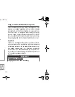
EBU18331
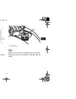
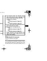
Speed limiter and air intake restrictor
plate
Your ATV was delivered with an adjustable speed
limiter and an air intake restrictor plate. Yamaha
recommends that all beginning riders start off with
the speed limiter adjusting screw fully turned in and
the air intake restrictor plate installed to limit the
amount of speed available while they learn.
The speed limiter keeps the throttle from fully
opening, even when the throttle lever is pushed to
the maximum. The adjusting screw may be gradu-
ally turned out as the beginner becomes more fa-
miliar with operating the ATV. Parents should
decide when to adjust the ATV for more power as
their youngster’s riding skills improve. Once the
ATV rider can operate with skill at the top speed
permitted by adjusting the speed limiter alone, the
air intake restrictor plate can be removed. Since re-
moval of this plate will result in a significant in-
crease in power, turn the adjusting screw
completely back in again; adjust it out in stages as
done previously.
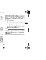
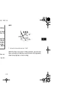
1. Loosen the locknut.
2. To increase the maximum engine power avail-
able and the maximum speed of the ATV, turn
the adjusting screw in direction (a). To de-
crease the maximum engine power available
and the maximum speed of the ATV, turn the
adjusting screw in direction (b).
NOTE:
Adjusting for maximum throttle lever movement
without removing the air intake restrictor plate will
cause the engine to run roughly at higher speeds.
(See page 8-17.)
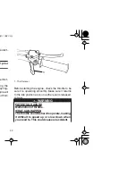
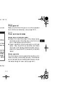
HOW TO AVOID THE HAZARD
Check the operation of the throttle lever be-
fore you start the engine. If it does not work
smoothly, check for the cause. Correct the
problem before riding the ATV. Consult a
Yamaha dealer if you can’t find or solve the
problem yourself.
Содержание RAPTOR YFM80RW
Страница 2: ......
Страница 9: ... 8 36 9 1 9 1 9 2 10 1 11 1 11 1 11 3 11 4 11 5 11 7 ...
Страница 14: ...1 5 ed ar may h with th ad ...
Страница 15: ...2 1 1 2 3 4 5 6 7 8 9 10 11 RNING AND SPECIFICATION LABELS ...
Страница 18: ...3 1 DESCRIPTION EBU17700 Right view 1 Spark arrester 2 Seat 3 Brake pedal 4 Footrest 2 1 4 3 ...
Страница 19: ...3 2 1 2 3 4 5 6 7 8 9 10 11 slightly from the figures shown in this manual 4 ...
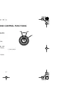
Страница 20: ...4 1 AND CONTROL FUNCTIONS esult in ows er and t be re be re 1 Main switch OFF ON 1 ...
Страница 32: ...4 13 esult in ...
Страница 39: ...5 7 1 2 3 4 5 6 7 8 9 10 11 re prop ches are distilled ...
Страница 48: ...6 9 esult in ...
Страница 49: ...7 1 1 2 3 4 5 6 7 8 9 10 11 DING YOUR ATV ...
Страница 57: ...7 9 1 2 3 4 5 6 7 8 9 10 11 uring op he rear ity for nd se or pull r brak r Own lling a ...
Страница 99: ...8 23 1 2 3 4 5 6 7 8 9 10 11 t the up ower ca oint will 6 Tighten the upper locknut a a 1 Cable joint 1 ...
Страница 119: ...10 4 1 2 3 4 5 6 7 8 9 10 11 ...
Страница 121: ...11 2 1 2 3 4 5 6 7 8 9 10 11 o identi n the il label in e need ha deal 1 Model label 1 ...
Страница 128: ...11 9 ...