


QL5/QL1
139
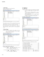
2-5. Fader Travel Time Measurement Test
Before this test, check to make sure that “FADER
CALIBRAION” on page 159 has been executed.
Press any 3 switches simultaneously in the Encoder Input Test
mode, and the Fader Travel Time Measurement Test mode will
be activated.
First, repeat reciprocal movement of all faders by the speci
fi
ed
number of times before taking measurement.
The check results are indicated with SEL/ON LEDs arranged
on each fader.
If ascending is NG,the SEL-LED turns on and if descending is
NG, the ON-LED turns on.
• Check to make sure that SEL/ON LEDs arranged on each
fader are all turned off.
It is possible to re-check by pressing whichever one switch.
2-3. Switch Input Test
Press any 3 switches simultaneously in the Respective Color
LEDs Lighting Test mode, and the Switch Input Test mode will
be activated.
Have the LEDs corresponding to each switch lit in advance,
press and release the switch, and the corresponding LEDs
should turn off.
In the same way, check all the switches.
Con
fi
rm visually if all the LEDs which were lit in advance have
been turned off.
For the switch without LED, have the nearby LEDs lit
correspondingly.
The SW reaction may be delayed as the reset in DANTE may
take a while.
As this is repeated once every ten over seconds depending on
the differences of the DANTE module, the symptom will no
longer appear if the cause is entered in DIAG after opening
DANTE SETUP from the SETUP screen in the normal mode
and then changing the SECONDARY PORT to REDUNDANT
before switching on the power again.
This problem does not occur during normal operations.
2-4. Encoder Input Test
Press any 3 switches simultaneously in the Switch Input Test
mode, and the Encoder Input Test mode will be activated.
Have the LEDs corresponding to each encoder lit in advance,
turn each encoder clockwise and counterclockwise one by one,
and the corresponding LED should turn off.
In the same way, check all the encoders.
Con
fi
rm visually that all LEDs which were lit in advance have
been turned off.
For the encoder without LED, have the nearby LEDs lit
correspondingly.
* For the corresponding LED of the encoder, the test is the same
as the Switch Input Test.
Encoder
Made to correspond to CH METER
GAIN
CH30/QL5(CH14/QL1) to -6
PAN
CH30/QL5(CH14/QL1) to -12
HPF
CH31/QL5(CH15/QL1) to -18
DYNAMICS 1
CH32/QL5(CH16/QL1) to -6
DYNAMICS 2
CH32/QL5(CH16/QL1) to -12
EQUALIZER-Q
CH30/QL5(CH14/QL1) to -30
EQUALIZER-Freq
CH31/QL5(CH15/QL1) to -30
EQUALIZER-GAIN
CH32/QL5(CH16/QL1) to -30
TOUCH AND TURN
CH30/QL5(CH14/QL1) to -0
Содержание QL5
Страница 5: ...5 QL5 QL1 QL5 QL1 19 828 4 272 563 Unit mm 468 272 562 19 DIMENSIONS...
Страница 85: ...85 QL5 QL1 CPUQL Circuit Board 2NA ZG33520 1 to DSP32 CN101 QL5 to DSP16 CN101 QL1 Pattern side...
Страница 86: ...QL5 QL1 86 2NA WY63530 Component side Scale 95 100 FX Circuit Board to DSP32 CN351 QL5 to DSP16 CN351 QL1...
Страница 87: ...87 QL5 QL1 2NA WY63530 Scale 95 100 FX Circuit Board not installed Pattern side...
Страница 90: ...QL5 QL1 90 B B DSP32 Circuit Board QL5 DSP16 Circuit Board QL1 2NA ZF60440...
Страница 91: ...91 QL5 QL1 B B Scale 85 100 Pattern side 2NA ZF60440...
Страница 92: ...QL5 QL1 92 HAAD Circuit Board C C 2NA ZH87070 1...
Страница 94: ...QL5 QL1 94 HAAD Circuit Board D D 2NA ZH87070 1...
Страница 95: ...95 QL5 QL1 D D Scale 58 100 Pattern side 2NA ZH87070 1...
Страница 101: ...101 QL5 QL1 JK Circuit Board to DSP32 CN751 QL5 to DSP16 CN751 QL1 Component side 2NA WY63490 1...
Страница 103: ...103 QL5 QL1 PNL PNCOM Circuit Board 2NA ZF60470 1 WR 31 0 1 Component side Pattern side...
Страница 104: ...QL5 QL1 104 2NA ZF60450 1 PN16M Circuit Board PN16S Circuit Board QL5 F F...
Страница 105: ...105 QL5 QL1 Component side 2NA ZF60450 1 Scale 90 100 F F...
Страница 108: ...QL5 QL1 108 PNR PNCOM Circuit Board 2NA ZF60470 1 Component side...
Страница 109: ...109 QL5 QL1 PNR PNCOM Circuit Board 2NA ZF60470 1 WR 31 0 1 WR 31 0 1 Pattern side...
Страница 110: ...QL5 QL1 110 FD1M FDCOM Circuit Board FD2 FDCOM Circuit Board QL5 FD1M FD2 2NA ZK68030 H H...
Страница 111: ...111 QL5 QL1 FD1M FD2 2NA ZK68030 H H Component side Scale 90 100...
Страница 113: ...113 QL5 QL1 Pattern side Scale 90 100 not installed I I FD1M FD2 2NA ZK68030...
Страница 114: ...QL5 QL1 114 Pattern side Component side FD1S FDCOM Circuit Board WR 6 1 2NA ZK68030...
Страница 150: ...QL5 QL1 150 2 H 3 O X O 4 BOX 5x4 1 18 LCD Test LCD LCD 1 3 2 9 5 OK NG 1...
Страница 169: ...QL5 QL1 169 5 Start QL OK Status Updating 1 1 6 OK Status Update Done 7 Status Error QL...
Страница 173: ...QL5 QL1 173 CD CD Ctrl Audio CD wav OK 01 01 Ctrl P 8 8 8 8 m ON ON OVER 10 00 dB 0 00 dB...
Страница 189: ...QL5 QL1 189 q w NG OK...
Страница 191: ...QL5 QL1 191 y u i o F1 F12 0 Port Setting error Ethernet Network...
Страница 200: ...QL5 QL1 9 20 20a 20c 20g 20b 20b 20d 20f 20e REAR L ASSEMBLY L Ass y JK SHEET ASSEMBLY JK Ass y 470 470a 470b Solder...
Страница 215: ...QL5 QL1 24 440 430 450 460 480 410 410 420 470 490 490 500 580 520 560 550 530 540 510 570 Bottom view Top view WIRING...
Страница 216: ...QL5 QL1 25 Assembly Outline View CONTROL PANEL S CS S CS Bottom view C10 C40 C30 C20 C50 C60 C30 C30 C80 C70 x2 x18 x15...