Additional information
Due to the upgrading of the firmware, the following functions are added or changed after the printing of the supplied owner’s manual.
The external input/output setting menu is changed and you can
connect multiple Projectphone systems to this unit for the
conference in a large room or with a large number of persons
(interlocked connection of Projectphone systems). The choices
are added to the “External I/O” menu for this change.
■
Connection
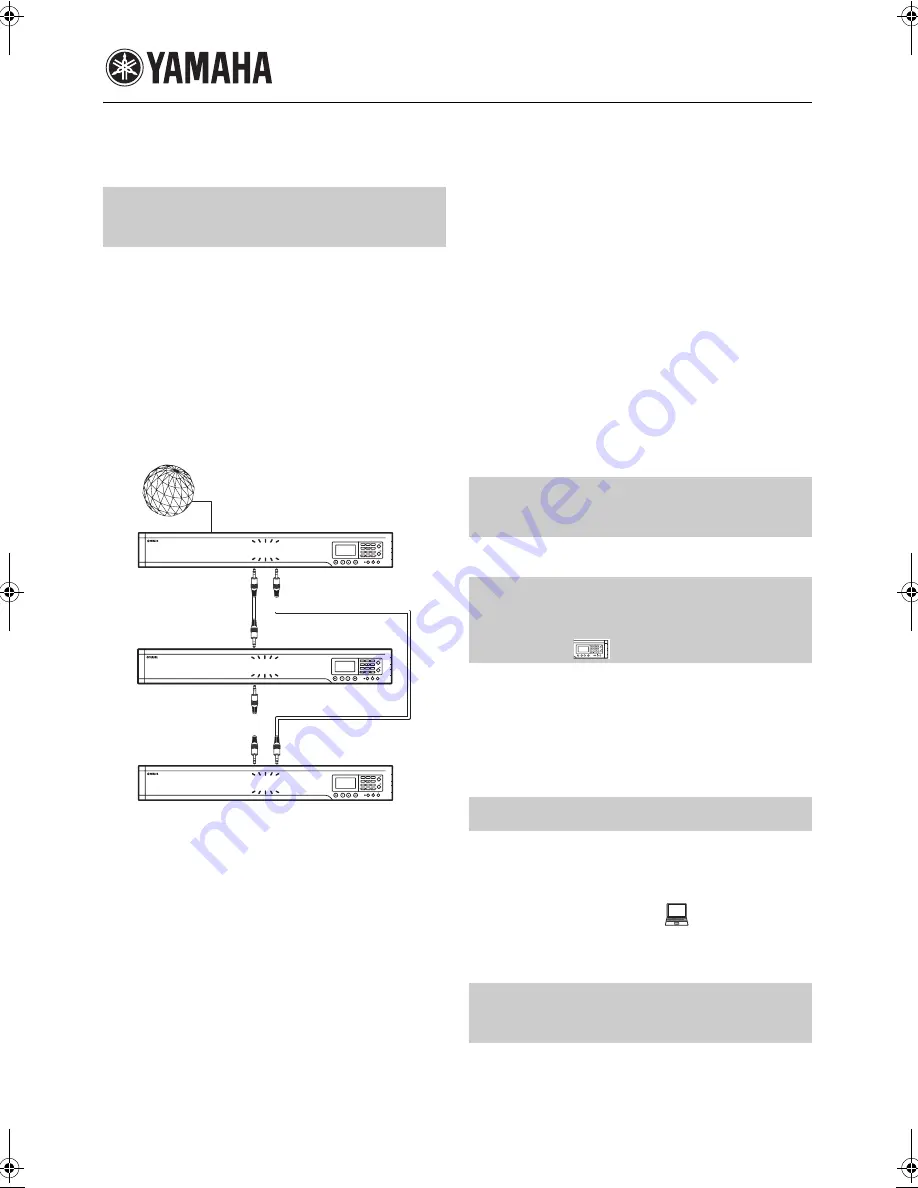
Using stereo mini-plug cables, connect the AUDIO OUT terminal
of each Projectphone system to the AUDIO IN terminal of
another Projectphone system. The following illustration shows an
example of an interlocked connection of three Projectphone
systems including this system.
■
Configuring the external input/output
setting
•
None (Default)
: Disable external input/output.
•
Audio
: Select this setting when connecting external audio
equipment to this unit. This setting is indicated on the initial
display.
•
Connection (mstr)
: Select this setting for the PJP-100H to be
used as the Master unit. This setting is indicated on the initial
display.
•
Connection (slv)
: Select this setting for the PJP-100H to be
used as the Slave unit. This setting is indicated on the initial
display.
Using the keys on this unit
In the initial display, select “Menu”
→
“Settings”
→
“Sound
Settings”
→
“External I/O”.
Using the Web menu
In the Web menu, select “External Input/Output”.
y
• In an interlocked connection of the Projectphone systems, allow
distance of at least 2 meters between them.
• Set the “Room Size” to “Small” for an interlocked connection.
• When connecting three Projectphone systems (Master, Slave 1
and Slave 2) in an interlocked connection, first connect the
AUDIO OUT terminal of the Master unit to the AUDIO IN
terminal of the Slave 1 unit. And then, connect the AUDIO
OUT terminal of the Slave 1 unit to the AUDIO IN terminal of
the Slave 2 unit. Finally, connect the AUDIO OUT terminal of
the Slave 2 unit to the AUDIO IN terminal of the Master unit.
• If echo or howling is produced, install the Projectphone systems
at larger distances or decrease their volumes.
• To avoid the echo or howling, set the volume level setting of
each Project Phone system to the same level.
The microphone indicators (blue LEDs) flash during muting.
Use this feature to control the ProjectPhone when it is used in
conjunction with PJP-MC24. Set “Remote Control” to “Enable”
to activate this feature.
Using the keys on this unit
In the initial display, select “Menu”
→
“Settings”
→
“General
Settings”
→
“Remote Control”.
Set the time zone of the region in which the system is used. The
time zone should be set in ±1-hour steps with respect to the UTC
(Coordinated Universal Time).
■
Setting the time zone
Using the Web menu
In the Web menu, select “Time”.
With the change in the specifications, this unit comparible with
G.729a codec and does not compatible with G.726-40 or G.726-
24 codec. You can select “G.729” and cannot select “G.726-40”
or “G.726-24” in the “CODEC” menu.
PJP-100H
F.W. 2.06
Interlocked Connection of
Projectphone Systems (Page 30)
1
2
3
4
5
6
7
8
9
0
MIC MUTE
LAN
VOL
DC IN 12V
IN
A
U
DIO OU
T
Master Unit
1
2
3
4
5
6
7
8
9
0
MIC MUTE
LAN
VOL
DC IN 12V
IN
A
U
DIO OU
T
Slave Unit
Internet, corporate LAN, etc.
AUDIO OUT
AUDIO IN
AUDIO IN
1
2
3
4
5
6
7
8
9
0
MIC MUTE
LAN
VOL
DC IN 12V
IN
A
U
DIO OU
T
Slave Unit
AUDIO OUT
AUDIO IN
AUDIO OUT
Microphone indicators during
muting (Pages 4 and 20)
Controlling the system using the
remote operation function
(Page 31)
Time Zone (Page 37)
Codec compatibility
(Pages 31 and 53)
1
2
3
4
5
6
7
8
9
0
MIC MUTE
LAN
VOL
DC IN
12V
IN AUDIO OU
T
PJP-100H_UCGB-Flier4.fm Page i Thursday, August 7, 2008 2:30 PM


