background image

PSR-540

17

All one touch setting (user) and song memory data, plus the other settings listed above, will be erased

and/or changed when the data initialization procedure is carried out.

Carrying out the data initialization procedure will usually restore normal operation if the PSR-540

freezes or begins to act erratically for any reason.

2.  INITIALIZE

Except for the data listed below, all PSR-540 panel settings are reset to their initial settings whenever the power

is turned on.  The data listed below are backed up (i.e. retained in the memory) as long as either an AC adaptor

is connected or a set of batteries is installed.

User Song Data

Metronome Volume

User One Touch Setting Data

Touch On/Off

One Touch Setting Bank Number

Touch Sensitivity

EZ Chord Data

Split Point

EZ Chord Bank Number Data

Accompaniment Split Point

Smart Chord Number

Footswitch Assign Function

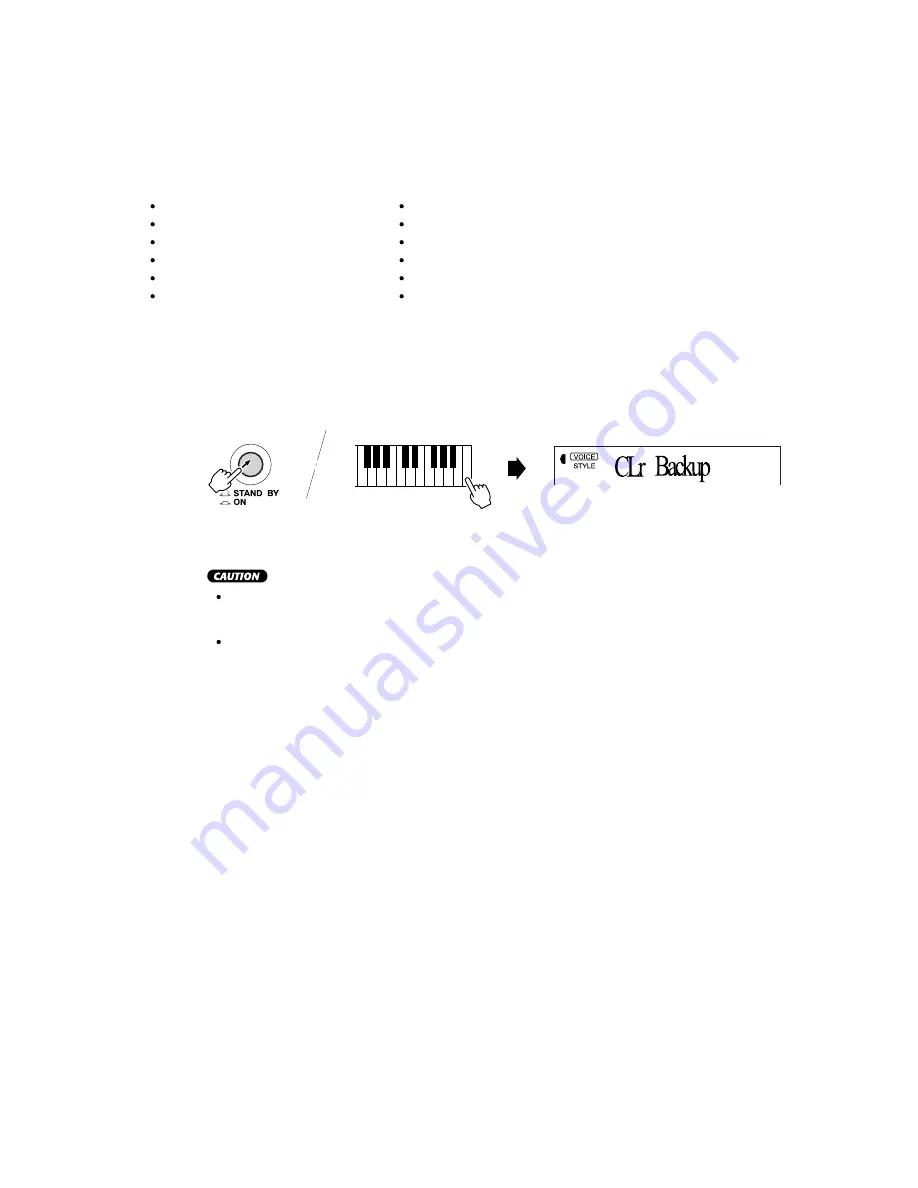
Data Initialization

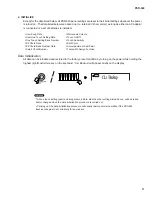
All data can be initialized and restored to the factory preset condition by turning on the power while holding the

highest (rightmost) white key on the keyboard. “CLr Backup” will appear briefly on the display.

Содержание Portatone PSR-540

Страница 1: ...IFICATIONS 3 PANEL LAYOUT 4 CIRCUIT BOARD LAYOUT 5 BLOCK DIAGRAM 6 DISASSEMBLY PROCEDURE 7 LSI PIN DESCRIPTION 9 IC BLOCK DIAGRAM 11 CIRCUIT BOARDS 12 TEST PROGRAM INITIALIZE 16 MIDI IMPLEMENTATION CHART 18 PARTS LIST OVERALL CIRCUIT DIAGRAM SERVICE MANUAL PK 001629 ...

Страница 2: ...PSR 540 6 28CA1 8813687 ...

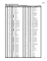
Страница 3: ...ry data bus 123 CMD0 I O Program memory Data bus 40 SMD15 I O Wave memory data bus 124 CMA21 O Program address bus 41 SOE O read signal 125 PDT15 I O SWX access data bus 42 SWE O write signal 126 PDT14 I O SWX access data bus 43 SRAS O RAS signal 127 PDT13 I O SWX access data bus 44 SCAS O CAS signal 128 PDT12 I O SWX access data bus 45 REFRESH O REFRESH signal 129 PDT11 I O SWX access data bus 46...

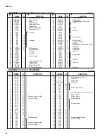
Страница 4: ... DS3 O 27 NUM3 I 59 VSS8 Ground 28 IFS I Host interface select 60 MON0 O 29 SFORM I Format data 61 MON1 O Motor on 30 INP I Index pulse 62 MON2 O 31 READY I Ready from FDD 63 MON3 O 32 WPRT I Write control signal 64 VSS9 Ground KS0065B XV933A00 LCD DRIVER PIN NO NAME I O FUNCTION PIN NO NAME I O FUNCTION 1 SC29 O 31 Vcc LCD driver circuit 5V 2 SC28 O 32 CL1 I Data shift 3 SC27 O 33 CL2 I Latch clo...

Страница 5: ...0 O 17 S6 O 57 C11 O 18 S5 O 58 C12 O 19 S4 O 59 C13 O 20 S3 O 60 C14 O 21 S2 O 61 C15 O 22 S1 O 62 C16 O 23 Vss Ground 63 S40 O 24 OSC1 I Oscillator 64 S39 O 25 OSC2 O Oscillator 65 S38 O 26 V1 66 S37 O 27 V2 67 S36 O 28 V3 Power supply 68 S35 O 29 V4 69 S34 O 30 V5 70 S33 O 31 CLK1 O Data latch clock 71 S32 O Segment signal output for LCD 32 CLK2 O Data shift clock 72 S31 O driving 33 Vdd Power ...

Страница 6: ...heck again Check that the LCD displays OK Note Do not turn on the power switch by normal mode while standing by as the RAM data will be lost 47 047 Factry Set All the RAMs are initialized and set to the factory preset date when executing this test The results appear on the LCD 48 048 Test Exit Exit from the test program after executing this test 1 001 Version Displays Rom version Rom Program Wave ...

Страница 7: ...henever the power is turned on The data listed below are backed up i e retained in the memory as long as either an AC adaptor is connected or a set of batteries is installed User Song Data Metronome Volume User One Touch Setting Data Touch On Off One Touch Setting Bank Number Touch Sensitivity EZ Chord Data Split Point EZ Chord Bank Number Data Accompaniment Split Point Smart Chord Number Footswit...

Страница 8: ...PSR 540 C1 Note See parts list for details of circuit board component parts ...

Страница 9: ...ote See parts list for details of circuit board component parts WARNING Components having special characteristics are marked and must be replaced with parts having specification equal to those originally installed ...

Отзывы: