PF-1000
49
Note: 0 dBm = 0.775 V
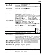
Time is required to complete the checks performed by test No. 43–47.
No.
LCD
Test Function and Judgment criteria
Check that the C3 note is output when pressing the damper pedal, and that the C4 note is output when
releasing. For the check result, check that “Damper Test OK” is displayed on the LCD display.
Connect the foot volume (FC-7) to the [AUX PEDAL 1] jack.
Check that the C3 note is output when fully pressing the pedal to the back (to maximum), and that the
C4 note is output when fully pressing the pedal to rhe front (to minimum). For the check result,
check that “Aux Pedal Check OK” is displayed on the LCD display.
After connecting the [MIDI IN] jack and [MIDI OUT] jack with a MIDI cable, execute the test. Set
the [HOST SELECT]switch to “MIDI”.
Check that the C4 note is output and that the LCD displays “MIDI Check OK”. If there is no input
after one second since signal output, it is judged NG.
Connect pin 3 to pin 5 and pin 6 to pin 8 of the [TO HOST] terminal, and execute the test.
Check that the following note sounds when changing the [HOST SELECT] switch position according
to the LCD indication; the LCD will display “TO HOST Check OK”. (PC1: note C3; PC2: note C4;
MAC: note C5) If there is no input after one second since signal output, it is judged NG.
Check the MIC output level.
Connect the level meter (with a JIS-C filter) to the [PHONES] jack. (PHONES L, R: 33 ohm load)
Apply a 1 kHz, - 50 dBm sine wave to the [MIC/LINE IN] jack.
Set the [MIC/LINE] select switch to [MIC] and set the [INPUT VOLUME] at maximum.
Set the [MASTER VOLUME] at the MAX. position and check the output level.
PHONES L, R: +5.5 dBm +/-2 dB
Checks the ROMs that are connected to the CPU bus.
Check the LCD “ROM Check2 OK”. It takes about 25 seconds.
Checks the RAMs that are connected to the CPU bus.
Check the LCD “RAM Check2 OK”.
Checks the Flash Memories that are connected to the CPU bus.
Check the LCD “Flash Check2 OK”. It takes about 35 seconds.
Checks the Wave ROMs.
Check the LCD “XG Wave ROM Check OK”. It takes about 100 seconds.
Checks the Wave RAMs.
Check the LCD “XG Wave RAM Check OK” “Natural Wave RAM1 Check OK”
Checks the NTSC red signal of “VIDEO OUT”.
Connect the TV to the [VIDEO OUT] jack and check that TV characters become red.
Checks the NTSC green signal of “VIDEO OUT”.
Connect the TV to the [VIDEO OUT] jack and check that TV characters become green.
Checks the NTSC blue signal of “VIDEO OUT”.
Connect the TV to the [VIDEO OUT] jack and check that TV characters become blue.
Checks the PAL red signal of “VIDEO OUT”.
Connect the TV to the [VIDEO OUT] jack and check that TV characters become red.
Checks the PAL green signal of “VIDEO OUT”.
Connect the TV to the [VIDEO OUT] jack and check that TV characters become green.
Checks the PAL blue signal of “VIDEO OUT”.
Connect the TV to the [VIDEO OUT] jack and check that TV characters become blue.
If this test is executed, the Flash ROMs will be initialized when the power is turned on in the next time.
Exit from the test program after executing this test.
34
35
40
41
42
43
44
45
46
47
48
49
50
51
52
53
55
56
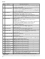
034: Damper Pedal Check
035: Aux Pedal Check
040: MIDI Check
041: TO HOST Check
042: MIC Check
043: ROM Check2
044: RAM Check2
045: Flash Check2
046: Wave ROM Check2
047: Wave RAM Check2
048: VIDEO OUT NTSC RED
(J and U models only)
049: VIDEO OUT NTSC GREEN
(J and U models only)
050: VIDEO OUT NTSC BLUE
(J and U models only)
051: VIDEO OUT PAL RED
(B, E, N models only)
052: VIDEO OUT PAL GREEN
(B, E, N models only)
053: VIDEO OUT PAL BLUE
(B, E, N models only)
055: Factory Set
056: Test Exit
Содержание PF-1000
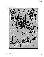
Страница 37: ...PF 1000 37 Pattern side DM Circuit Board R330 DM 2NA V716590 2 4 パターン側 ...
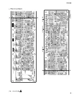
Страница 38: ...PF 1000 38 Component side Pattern side SWX 2NA V716050 2 to DM CN10 SWX Circuit Board 部品側 パターン側 ...
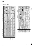
Страница 41: ...PF 1000 41 Pattern side PNR Circuit Board PNR 2NA V91530 2 0 C C C C パターン側 ...

