background image

216

Chapter 18—MIDI

01V96 Version 2—Owner’s Manual

• SLOT

If an optional “MY8-mLAN” I/O card is installed in the slot, MIDI data transfer to and from 
an external MIDI device is available via the MY8-mLAN card. 

MIDI Port Setup

Selecting a Port for MIDI Message Transfer

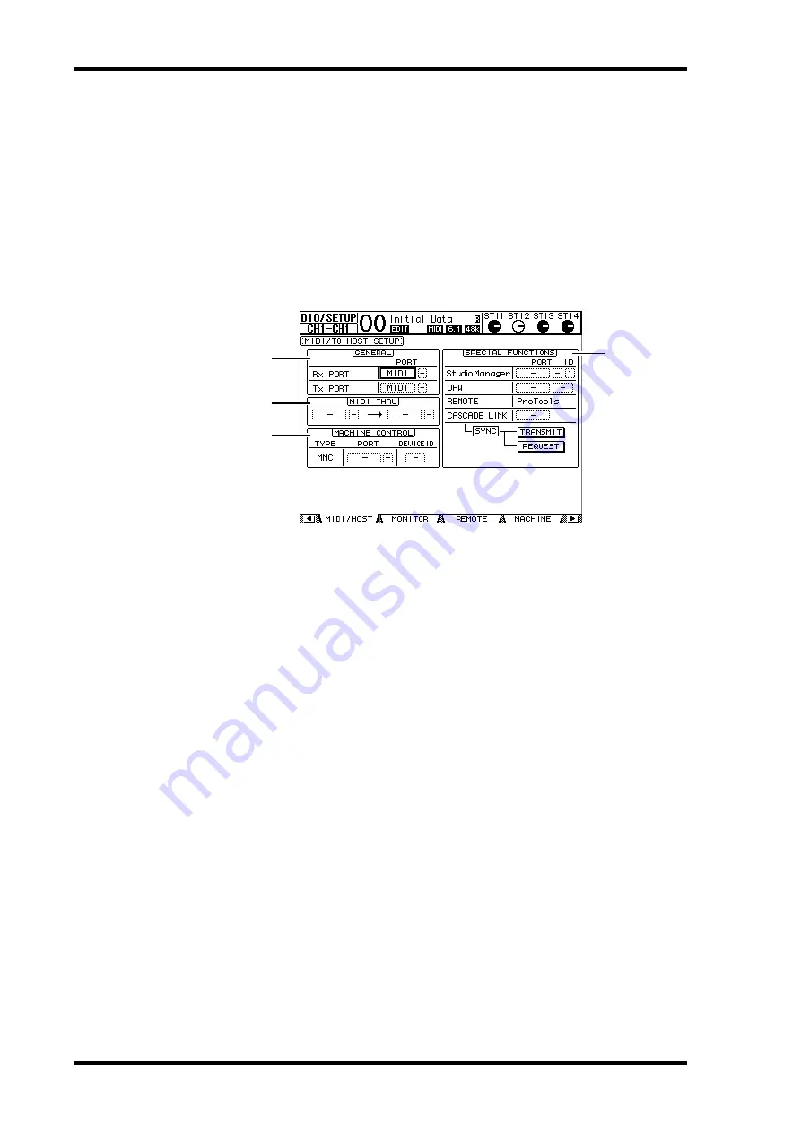
To configure MIDI ports for MIDI message transfer, press the DISPLAY ACCESS 
[DIO/SETUP] button repeatedly until the DIO/Setup | MIDI/Host page appears. This page 
enables you to set MIDI message input and output.

The following parameters are available on this page:

A

GENERAL section

This section enables you to select ports that transmit and receive MIDI messages, such 
as Program Changes and Control Changes.

Rx PORT

....................... This parameter specifies a port for general MIDI data recep-

tion. In the left parameter box, select MIDI, USB, or SLOT. If 
you select USB or SLOT, specify the port number (1–8) in the 
right parameter box.

Tx PORT

....................... This parameter specifies a port for general MIDI data transmis-

sion. The available ports are the same as for the Rx PORT 
parameter.

B

MIDI THRU section

These parameters enable you to route incoming MIDI data from one port or slot to 
another without changes. Select a port for reception in the first parameter box, and 
select a port for transmission in the next parameter box (located to the right of the 
arrow). If you select USB or SLOT, specify the port number in the small parameter box 
adjacent to the port parameter box.

C

MACHINE CONTROL section

This section enables you to select a remote control method and a remote control port to 
control external devices that support MMC, such as a hard disk recorder.

PORT

............................. Select MIDI, USB, or SLOT for MMC command transfer. If 

you select USB or SLOT, specify the port number in the right 
parameter box.

4

1

2

3

Содержание O1V96

Страница 1: ...E Owner s Manual Keep This Manual For Future Reference ...

Страница 2: ...hose products distributed by Yamaha Corporation of America or its subsidiaries FCC INFORMATION U S A IMPORTANT NOTICE FOR THE UNITED KINGDOM Connecting the Plug and Cord WARNING THIS APPARATUS MUST BE EARTHED IMPORTANT The wires in this mains lead are coloured in accordance with the following code GREEN AND YELLOW EARTH BLUE NEUTRAL BROWN LIVE As the colours of the wires in the mains lead of this ...

Страница 3: ...es and a third grounding prong The wide blade or the third prong are provided for your safety If the pro vided plug does not fit into your outlet consult an electrician for replacement of the obsolete outlet 10 Protect the power cord from being walked on or pinched particularly at plugs convenience receptacles and the point where they exit from the apparatus 11 Only use attachments accessories spe...

Страница 4: ...service personnel CAUTION Always follow the basic precautions listed below to avoid the possibility of physical injury to you or others or damage to the device or other property These precautions include but are not limited to the following Remove the electric plug from the outlet when the device is not to be used for extended periods of time or during electrical storms When removing the electric ...

Страница 5: ...backup battery is running low when you turn on the device the display indicates WARNING Low Battery In this case immediately save the data to an external media using MIDI Bulk Dump then have qualified Yamaha service personnel replace the backup battery Using a mobile telephone near this unit may induce noise If noise occurs use the telephone away from the unit The digital circuits of this unit may...

Страница 6: ...or function of the 01V96 The Input and Output Channels are explained in the following chapters Input Channels Bus Outs and Aux Outs Where possible these chapters have been organized in order of sig nal flow from input to output Conventions Used in this Manual The 01V96 features two types of buttons physical buttons that you can press e g ENTER and DISPLAY and buttons that appear on the display pag...

Страница 7: ...ter function enables you to mute all channels in a Mute group simultaneously page 153 Internal Effects You can add optional Add On Effects to the preset effects page 162 Scene Memory Any channel or parameter settings in the current scene can be copied and pasted into other scenes page 173 You can select additional parameters for the Recall Safe function page 172 Remote Control Cubase SX has been a...

Страница 8: ...al Inputs Outputs 71 Converting Sampling Rates of Signals Received at I O Card Inputs 72 Monitoring Digital Input Channel Status 73 Dithering Digital Outputs 74 Setting the Transfer Format for Higher Sampling Rates 75 7 Input Channels 77 About Input Channels 77 Setting the Input Channels from the Display 79 Setting the Input Channels from the Control Surface 90 Pairing Input Channels 92 Naming Inp...

Страница 9: ...oup Master 152 Using Mute Group Master 153 Linking EQ and Compressor Parameters 154 14 Internal Effects 157 About the Internal Effects 157 Using Effects Processors via Aux Sends 158 Inserting the Internal Effects into Channels 160 Editing Effects 161 About Add On Effects 162 About Plug Ins 163 15 Scene Memories 165 About Scene Memories 165 What is Stored in a Scene 165 About Scene Numbers 166 Stor...

Страница 10: ...er Lists 247 USER DEFINED KEYS 247 USER DEFINED KEYS Initial Assignments 249 Input Patch Parameters 249 Initial Input Patch Settings 251 Output Patch Parameters 253 Initial Output Patch Settings 255 User Defined Remote Layer Initial Bank Settings 256 Effects Parameters 260 Effects and tempo synchronization 270 Preset EQ Parameters 271 Preset Gate Parameters fs 44 1 kHz 272 Preset Compressor Parame...

Страница 11: ...ign functions to control 01V96 internal parameters ADAT optical connectors Expansion slot for optional digital I O AD and DA cards Sonic Specifications Linear 24 bit 128 times oversampling A D converters Linear 24 bit 128 times oversampling D A converters 20 Hz through 40 kHz frequency response at 96 kHz sampling rate 106 dB typical dynamic range 32 bit internal signal processing 58 bit accumulato...

Страница 12: ...annel effects Apply effects via Aux Sends or Channel Inserts Effect library for storing and recalling effect settings Optional Add On Effects packages for adding effects that utilize a variety of new algo rithms Scene Memory Scene memories for storing and recalling mix settings as Scenes Surround Sound Supports 3 1 5 1 and 6 1 channel surround sound production Surround channel outputs can be assig...

Страница 13: ... 4 AUX 8 AUX 7 AUX 6 AUX 5 HOME METER DYNAMICS EQ EFFECT VIEW PATCH UTILITY MIDI SCENE DIO SETUP INSERT DELAY PAN ROUTING PAIR GROUP A B A B A B A B A B A B A B A B A B A B A B A B 16 15 13 12 11 10 9 8 7 6 4 3 2 1 5 14 INSERT I O INSERT I O INSERT I O INSERT I O INSERT I O INSERT I O INSERT I O INSERT I O INSERT I O INSERT I O INSERT I O INSERT I O L R IN OUT 2TR 10dBV UNBAL PHANTOM 48V CH9 12 CH...

Страница 14: ...the AD 15 16 button is turned off page 15 C INSERT I O connectors These unbalanced TRS phone type connectors are used for channel insert ins and outs Use a split cable to insert an external effects processor to AD input channels PEAK SIGNAL PEAK SIGNAL PEAK SIGNAL PEAK SIGNAL PEAK SIGNAL PEAK SIGNAL PEAK SIGNAL PEAK SIGNAL PEAK SIGNAL PEAK SIGNAL PEAK SIGNAL CH15 16 2TR IN 4 26 GAIN 4 26 GAIN 4 26...

Страница 15: ...der When the AD15 16 selector in the AD Input section 8 is turned on pushed in the sig nals input at the 2TR IN connectors are routed to AD Input Channels 15 and 16 When the Monitor Source selector 2 is turned on pushed in you can monitor the 2TR IN signals from the MONITOR OUT connectors The 2TR OUT signals are always the same as the STEREO OUT signals B Monitor Source selector This button select...

Страница 16: ...he selected channels The SOLO button indicator of the cur rently soloed channel lights up C ON buttons These buttons turn the selected channels on or off The ON button indicators for On channels light up D Channel faders Depending on the button selected in the FADER MODE section see page 17 these faders adjust the selected channel input levels or the Bus Out or Aux Out levels STEREO Section A SEL ...

Страница 17: ... off E Level controls These controls adjust the ST IN channel levels FADER MODE Section A AUX 1 AUX 8 buttons These buttons enable you to select the Aux Send you wish to control Pressing one of these buttons switches the Fader mode see page 33 and displays the corresponding Aux page The selected button s indicator lights up You can now adjust the send level of signals routed from Input Channels to...

Страница 18: ...t the level of signals routed from Buses 1 8 to the Stereo Bus and adjust the stereo or surround pan settings see pages 85 135 G PAIR GROUP button This button displays a Pair Grup page enabling you to create or cancel channel pairs and group multiple channel faders or ON buttons see pages 93 149 H PATCH button This button displays a Patch page enabling you to patch input signals and Bus Out signal...

Страница 19: ...n This button selects the Remote Layer as the layer controlled in the Channel Strip section You can use this layer to control external MIDI devices or computer based DAWs See page 189 for more information on the Remote layer Display Section A Display This is a 320 x 240 dot LCD display with a backlight B Stereo meters These 12 segment level meters display the final output level of the Stereo Bus C...

Страница 20: ...an of the channel selected by the SEL button B HIGH button C HIGH MID button D LOW MID button E LOW button These buttons select the EQ band HIGH HIGH MID LOW MID LOW of the channel selected by the SEL button The corresponding button indicator of the currently selected band lights up F Q control This control adjusts the currently selected band Q G FREQUENCY control This control adjusts the currentl...

Страница 21: ...ene to store or recall Pressing the Scene Up button increments the selection pressing the Scene Down button decrements the selection Holding down either key increments or decrements the selection continuously C RECALL button This button recalls the Scene memory selected by the Scene Up Down buttons USER DEFINED KEYS Section A 1 8 buttons You can assign any of the 167 functions to these User Define...

Страница 22: ...d parameter values C DEC INC buttons These buttons increment or decrement a parameter value by one Pressing the INC but ton increments the value pressing the DEC button decrements the value Holding down either key increments or decrements the value continuously D Left Right Up Down cursor buttons These buttons move the cursor around the display pages or select parameters and options Holding down a...

Страница 23: ...are on 48V phantom power is supplied to the INPUT A con nectors AD Output Section A MONITOR OUT connectors L R These balanced TRS phone type con nectors output monitoring signals or 2TR IN signals The nominal signal level is 4 dB You can select signals using the Mon itor Source selector PHANTOM 48V p 23 Power Section p 25 AD Output Section p 23 SLOT Section p 25 MIDI Control Section p 25 Digital I...

Страница 24: ...nector inputs a wordclock signal from a connected external device to the 01V96 C ADAT IN OUT connectors These optical TOSLINK connectors input and output ADAT digital audio signals D 2TR OUT DIGITAL COAXIAL This RCA phono connector outputs consumer format IEC 60958 digital audio The con nector is typically used to connect the digital stereo input consumer format of a DAT recorder MD recorder or CD...

Страница 25: ...rt optional mini YGDAI cards into this slot See page 26 for information on installing these cards Power Section A POWER ON OFF switch This switch turns the power to the 01V96 on or off B AC IN connector This connector enables you to connect the 01V96 to an AC outlet via the supplied power cord Note To prevent loud clicks and thumps in your speakers turn on your audio equipment in the following ord...

Страница 26: ... Make sure that the power to the 01V96 is turned off 2 Undo the two fixing screws and remove the slot cover as shown below Keep the cover and fixing screws in a safe place for future use 3 Insert the card between the guide rails and slide it all the way into the slot as shown below You may have to push firmly to fully insert the card into the internal connector 4 Secure the card using the attached...

Страница 27: ...haracters are the channel s Short name You can edit the channel s Short name if you desire see page 229 C Current Scene This section indicates the number and title of the currently selected Scene memory see page 166 If the selected Scene is write protected a padlock icon appears D EDIT indicator Thisindicatorappearswhenthecurrentmixsettingsnolongermatchthoseof theScene that was most currently reca...

Страница 28: ...rently displayed tabs by pressing the F1 F4 buttons If the selected display page group contains multiple pages press the F1 F4 buttons below the corresponding tab to select a specific page 3 To select a page for which a tab is not currently displayed press either the Left or Right Tab Scroll button depending on where the page is located to display the page tab then press the corresponding F1 F4 bu...

Страница 29: ... the ENTER button to turn the func tion on highlighted or off The buttons also enable you to select one of two options or to execute certain functions Parameter Boxes The parameter boxes enable you to select one of multiple options Press the cursor buttons to move the cursor to a parameter box then rotate the Parameter wheel or press the INC DEC buttons to select the setting You may need to press ...

Страница 30: ...he fig ure on the right shows lowercase characters and numbers Use the cursor buttons to select characters and press the ENTER button to enter them into the title The cursor moves to the right automatically as each character is entered Use the Parameter wheel to move the cursor within the title Use the SHIFT LOCK button to select uppercase or lowercase characters and use the SPC button to enter a ...

Страница 31: ...tons Layers Channel Strips 1 8 9 16 1 16 button Input Channel Layer 1 16 Input Channels 1 16 17 32 button Input Channel Layer 17 32 Input Channels 17 32 REMOTE button Remote Layer Operation depends on the selected target see page 189 MASTER button Master Layer Aux Send masters 1 8 Bus Out masters 1 8 Tip The function of each channel strip fader depends on the currently selected Fader mode see page...

Страница 32: ...rrently displayed page contains a relevant channel parameter the cursor moves to that parameter automati cally If the currently displayed page contains no such parameter a page that does contain such a parameter is selected automatically 3 To select the Stereo Out press the STEREO SEL button Repeatedly pressing the STEREO SEL button toggles between the Stereo Out left and Ste reo Out right channel...

Страница 33: ...owing table shows the channel fader functions for each Layer and Fader mode LAYER buttons Fader Mode Channel Strip Fader 1 8 9 16 1 16 button HOME button Input Channel 1 16 level AUX1 AUX8 buttons Input Channel 1 16 Aux Send level 17 32 button HOME button Input Channel 17 32 level AUX1 AUX8 buttons Input Channel 17 32 Aux Send level REMOTE button HOME button Operation depends on the selected targe...

Страница 34: ... IN Channel signals B OUTPUT section This section enables you to select the metering position for Output Channel Aux Out 1 8 Bus Out 1 8 Stereo Out signals 2 Move the cursor to the desired parameter button in the INPUT or OUTPUT section then press ENTER You can select one of the following three positions in each section PRE EQ Immediately before EQ PRE FADER Immediately before the fader POST FADER...

Страница 35: ...s page displays the left and right ST IN Channel 1 4 levels separately Master page This section displays the Output Channel Aux Out 1 8 Bus Out 1 8 Stereo Out levels altogether Effect page This page displays the internal effects processor 1 4 input and output levels altogether ...

Страница 36: ...1 32 COMP GR The amount of gain reduction for the compressor LEVEL Input Channel input level or Output Channel output level 4 To activate the Peak Hold function move the cursor to the PEAK HOLD but ton then press ENTER The PEAK HOLD button turns on and the peak level is held on the meters on the page To cancel the Peak Hold function turn the PEAK HOLD button off Tip Thesepagesalsoallowyoutochanget...

Страница 37: ... 60 GAIN 16 60 GAIN 16 60 GAIN 16 60 GAIN 16 60 GAIN 16 60 GAIN 16 60 PAD FADER MODE DISPLAY ACCESS AUX 1 AUX 1 AUX 2 AUX 3 AUX 4 AUX 5 AUX 6 AUX 7 AUX 8 BUS 1 BUS 2 BUS 3 BUS 4 BUS 5 BUS 6 BUS 7 BUS 8 AUX 2 AUX 3 AUX 4 AUX 8 AUX 7 AUX 6 AUX 5 HOME METER DYNAMICS EQ EFFECT VIEW PATCH UTILITY MIDI SCENE DIO SETUP INSERT DELAY PAN ROUTING PAIR GROUP A B A B A B A B A B A B A B A B A B A B A B A B 16...

Страница 38: ... AUX 3 AUX 4 AUX 8 AUX 7 AUX 6 AUX 5 HOME METER DYNAMICS EQ EFFECT VIEW PATCH UTILITY MIDI SCENE DIO SETUP INSERT DELAY PAN ROUTING PAIR GROUP A B A B A B A B A B A B A B A B A B A B A B A B 16 15 13 12 11 10 9 8 7 6 4 3 2 1 5 14 INSERT I O INSERT I O INSERT I O INSERT I O INSERT I O INSERT I O INSERT I O INSERT I O INSERT I O INSERT I O INSERT I O INSERT I O L R IN OUT 2TR 10dBV UNBAL PHANTOM 48V...

Страница 39: ...HOME METER DYNAMICS EQ EFFECT VIEW PATCH UTILITY MIDI SCENE DIO SETUP INSERT DELAY PAN ROUTING PAIR GROUP A B A B A B A B A B A B A B A B A B A B A B A B 16 15 13 12 11 10 9 8 7 6 4 3 2 1 5 14 INSERT I O INSERT I O INSERT I O INSERT I O INSERT I O INSERT I O INSERT I O INSERT I O INSERT I O INSERT I O INSERT I O INSERT I O L R IN OUT 2TR 10dBV UNBAL PHANTOM 48V CH9 12 CH5 8 CH1 4 INPUT BAL INSERT ...

Страница 40: ...Wordclock Connections To establish wordclock synchronization between the 01V96 and external devices you can distribute wordclock signals independently via dedicated cables or you can use clock infor mation derived from digital audio connections The WORD CLOCK IN and OUT connectors transmit and receive wordclock signals inde pendently on the 01V96 The following examples show two ways in which wordc...

Страница 41: ...B 20dB 20dB 20dB 20dB 20dB 20dB 16 60 GAIN 16 60 GAIN 16 60 GAIN 16 60 GAIN 16 60 GAIN 16 60 GAIN 16 60 GAIN 16 60 GAIN 16 60 GAIN 16 60 PAD FADER MODE DISPLAY ACCESS AUX 1 AUX 1 AUX 2 AUX 3 AUX 4 AUX 5 AUX 6 AUX 7 AUX 8 BUS 1 BUS 2 BUS 3 BUS 4 BUS 5 BUS 6 BUS 7 BUS 8 AUX 2 AUX 3 AUX 4 AUX 8 AUX 7 AUX 6 AUX 5 HOME METER DYNAMICS EQ EFFECT VIEW PATCH UTILITY MIDI SCENE DIO SETUP INSERT DELAY PAN RO...

Страница 42: ...nds on the type of I O card installed adat These buttons select the inputs from the ADAT IN connector on the rear panel Inputs are selected in pairs odd and even numbers in this order WC IN This button selects the wordclock signal input at the WORD CLOCK IN connector on the rear panel 2TRD This button selects the 2TR IN DIGITAL input as the word clock source INT 44 1k INT 48k INT 88 2k INT 96k The...

Страница 43: ...urrently assigned to Input Channels are shown in the parameter boxes 1 beneath the channel numbers The parameter indicators are explained below No assignment AD1 AD16 INPUT connectors 1 16 ADAT1 ADAT8 ADAT IN channels 1 8 SL 01 SL 16 Slot channels 1 16 FX1 1 FX1 2 Outputs 1 2 of Internal Effects Processor 1 FX2 1 FX2 2 Outputs 1 2 of Internal Effects Processor 2 FX3 1 FX3 2 Outputs 1 2 of Internal...

Страница 44: ... boxes 1 underneath the connector numbers The parameter indicators are explained below No assignment BUS1 BUS8 Bus Out 1 8 signals AUX1 AUX8 Aux Out 1 8 Signals ST L R Stereo Out signals INS CH1 INS CH32 Input Channels 1 32 Insert Outs INS BUS1 INS BUS8 Bus Out 1 8 Insert Outs INS AUX1 INS AUX8 Aux Out 1 8 Insert Outs INS ST L ST R Stereo Out Insert Outs CAS BUS1 BUS8 Bus Out 1 8 Cascade Outs CAS ...

Страница 45: ... 2 Use the cursor buttons to move the cursor to a patch parameter 1 you wish to change and rotate the Parameter wheel or press the INC DEC buttons to modify the patching 3 Press ENTER to confirm the change Tip To restore the default patching recall Output Patch memory 00 see page 179 ...

Страница 46: ...46 Chapter 4 Connections and Setup 01V96 Version 2 Owner s Manual ...

Страница 47: ... 20dB 16 60 GAIN 16 60 GAIN 16 60 GAIN 16 60 GAIN 16 60 GAIN 16 60 GAIN 16 60 GAIN 16 60 GAIN 16 60 GAIN 16 60 PAD FADER MODE DISPLAY ACCESS AUX 1 AUX 1 AUX 2 AUX 3 AUX 4 AUX 5 AUX 6 AUX 7 AUX 8 BUS 1 BUS 2 BUS 3 BUS 4 BUS 5 BUS 6 BUS 7 BUS 8 AUX 2 AUX 3 AUX 4 AUX 8 AUX 7 AUX 6 AUX 5 HOME METER DYNAMICS EQ EFFECT VIEW PATCH UTILITY MIDI SCENE DIO SETUP INSERT DELAY PAN ROUTING PAIR GROUP A B A B A...

Страница 48: ...om the hard disk recorder are routed to Input Channels 25 32 If the Input Patch settings have been changed from the default settings recall Input Patch memory 00 from the Input Patch library page 175 Tip See page 40 for more information on wordclock See page 75 for more information on 01V96s running at higher sampling frequencies 88 2 kHz or 96 kHz Note You can select the 01V96 internal clock as t...

Страница 49: ...ectors 1 12 Setting the Input Levels 1 Cue the musicians to play the musical instru ments connected to INPUT connectors 1 12 while adjusting the corresponding PAD switches and GAIN controls so that the PEAK indicators temporarily flash at the highest volumes 2 Press the LAYER 1 16 button Input Channel Layer 1 16 is now available for control from the channel strip section 3 Press the FADER MODE HOM...

Страница 50: ...s using the level meters on the display Pairing Channels On the 01V96 you can pair adjacent odd even channels for stereo operation Faders and most mix parameters of paired channels excluding the Input Patch phase routing and pan parameters are linked Pairing Input Channels is useful when you are connecting ste reo sources such as a rhythm machine or synthesizer 1 To pair adjacent odd even Input Ch...

Страница 51: ...d 2 Tip Youcanstillselectoneof thepairedchannelsforcontrolbypressingthecorresponding SEL button When you select the channel the SEL button indicator lights up and the SEL button for the paired partner flashes You can also determine how to copy the parameter settings to the paired partner by using a special window see page 230 You can create or cancel pairs on the Pair Grup pages see page 93 You ca...

Страница 52: ...y to display the Pan Route Rout1 16 page This page enables you to select a Bus Out as the signal destination for each channel This page contains the following buttons A 1 8 buttons These buttons route Input Channel signals to Buses 1 8 You can select multiple but tons B S button This button routes Input Channel signals to the Stereo Bus C D button This button routes Input Channel signals to the sp...

Страница 53: ...In this example Input Channels 1 4 are assigned to Buses 1 and 2 and Input Channels 5 8 are assigned to Buses 3 and 4 4 Press the PAN ROUTING button repeatedly to display the Pan Route Pan page This page enables you to set the panpots for signals routed from the Input Channels to the Stereo Bus and for signals routed from the Input Channels to the odd even buses 5 Move the cursor to the PAN parame...

Страница 54: ...igital MTR in record ready mode routingthesignalssenttoTracks1 8of thedigitalMTRbacktothe01V96 sInputChannels 17 24 then patching them to the MONITOR OUT connectors and the PHONES jack 1 Arm the connected digital MTR s tracks for recording At this time set the monitor mode on the digital MTR accordingly so that you can monitor the input signals on the armed tracks Refer to the owner s manual for t...

Страница 55: ... are steadily lit then raise the STE REO fader to 0 dB 7 While the musicians play the musical instruments adjust faders 1 8 MON ITOR OUT control and PHONES control to set the appropriate monitoring level Now you can monitor via the monitoring system and headphones the signals sent from Input Channels 17 24 to the Stereo Bus Tip Controlling Input Channel 17 32 Pan settings faders and the ON buttons...

Страница 56: ...n then the F1 button to display the EQ EQ Edit page The EQ Edit page enables you to adjust the EQ parameters for the currently selected chan nel 4 Make sure that the EQ ON button in the upper left corner is turned ON The EQ ON OFF button turns the currently selected Input Channel s EQ on or off If the button is off press the ENTER button to turn it on 5 While a musician plays the musical instrumen...

Страница 57: ...orded to the tracks 1 Press the LAYER 1 16 button Input Channel Layer 1 16 is now available for control from the channel strip section 2 Press the SEL button of the Input Channel to which you want to apply com pression Tip Turn the Q parameter control for the LOW band clockwise all the way to set the LOW band EQ to L SHELF low shelving and counter clockwise all the way to set it to HPF high pass f...

Страница 58: ...ple uses one of the compressor programs 1 36 from the Compressor library 4 Rotate the Parameter wheel to scroll the library title list and select a pro gram that you want to recall The selected program appears inside the dotted box 5 Move the cursor to the RECALL button located to the left of the library title list then press ENTER The selected program is recalled 6 Press the F3 button The 01V96 d...

Страница 59: ...ding on the digital MTR and cue the musicians to start playing the musical instruments During recording press the HOME button to display the Meter CH1 32 page or the Master page and check to confirm that the Input Channel levels and Bus 1 8 output levels are not clipping 2 When you finish playing stop the digital MTR 3 To check the recording play the digital MTR from the beginning 4 If you are sat...

Страница 60: ... indicators temporarily flash at the highest volumes 2 Press the LAYER 1 16 button Input Channel Layer 1 16 is now available for control from the channel strip section 3 Press the DISPLAY ACCESS HOME button then press the F1 button to dis play the Meter CH1 32 page 4 Make sure that ON button indicators for the channels to which the instru ments or microphone are connected are lit then raise the co...

Страница 61: ...nel 1 and 2 signals are now routed to Slot output channels 1 and 2 then output to Tracks 9 and 10 on the digital MTR Adjusting the Monitoring Level Follow the steps below to place the digital MTR in record ready mode and monitor the sig nals that are sent from Tracks 9 and 10 of the digital MTR back to the 01V96 s Input Chan nels 25 and 26 through the MONITOR OUT connectors and the PHONES jack 1 A...

Страница 62: ...opriate monitoring level If necessary play back the recording on the digital MTR and adjust the volume balance between the recorded and recording signals Recording 1 Start recording on the digital MTR and cue the musicians to start playing the musical instruments while monitoring the recorded tracks During recording display the Meter CH1 32 page and confirm that the Input Channel levels are not cl...

Страница 63: ...CH15 16 2TR IN LEVEL PHONES LEVEL 0 10 0 10 4 26 GAIN 4 26 GAIN 4 26 GAIN GAIN 4 26 GAIN 20dB 16 60 GAIN 20dB 16 60 GAIN 20dB 20dB 20dB 20dB 20dB 20dB 20dB 20dB 20dB 20dB 16 60 GAIN 16 60 GAIN 16 60 GAIN 16 60 GAIN 16 60 GAIN 16 60 GAIN 16 60 GAIN 16 60 GAIN 16 60 GAIN 16 60 PAD FADER MODE DISPLAY ACCESS AUX 1 AUX 1 AUX 2 AUX 3 AUX 4 AUX 5 AUX 6 AUX 7 AUX 8 BUS 1 BUS 2 BUS 3 BUS 4 BUS 5 BUS 6 BUS ...

Страница 64: ...tly selected 6 Turn off the ON button for ST IN Channel 2 The button indicator turns off This ON button should be turned on only when you monitor the playback signal of the master recorder Adjusting the Track Mix Balance Follow the steps below to adjust the mix balance among Tracks 1 16 and process the signals using the EQ compressor and gate 1 Make sure that Tracks 1 16 on the digital MTR are all...

Страница 65: ...parameters using the buttons and controls in the SELECTED CHANNEL sec tion Compressing the track signals Select the desired channel by pressing the corresponding SEL button press the DYNAM ICS button then press the F4 button to display the Dynamics Comp Lib page and recall the desired compressor program see page 82 Press the DYNAMICS button then press the F3 button to display the Comp Edit page th...

Страница 66: ...1 is patched to ST IN Channel 1 L and R as shown in the diagram above 2 Make sure that the ON button for ST IN Channel 1 in the ST IN section is turned on 3 Press the DISPLAY ACCESS EFFECT button repeatedly until the Effect FX1 Lib page appears The Effect FX1 Lib page enables you to recall effect programs to be used by Effects proces sor 1 from the Effects library and store the current effects set...

Страница 67: ...are lit faders 1 16 control the Aux 1 8 send levels In this example the faders control the send level of the signals routed from Input Channels 17 32 to Aux 1 Effects processor 1 input 8 While playing back the recording on the digital MTR from the beginning operate faders 1 16 to adjust the send level of the signals routed from Input Channels to Effects processor 1 9 To adjust the effect return le...

Страница 68: ... in the ST IN section The button indicator lights up 4 Play back the recording on the master recorder The playback signal is input at the 01V96 s 2TR IN DIGITAL connector then routed through ST IN Channel 2 to the Stereo bus When the master recorder finishes playing back turn off the ON button for ST IN Chan nel 2 Note Most consumer type DAT recorders and MD recorders are unable to synchronize to ...

Страница 69: ...and B con nectors of the same number only the signal from INPUT B is effec tive e g B 2 takes priority over A 2 INPUT connectors 13 16 These balanced TRS type phone connectors accept line level signals When the AD 15 16 source selector is turned on pushed in signals from INPUT 15 and 16 are ignored Instead signals from the 2TR IN connector will be routed to AD Input Channels 15 and 16 INSERT I O c...

Страница 70: ... rear panels feature output connectors that enable you to connect a mon itoring system master recorder effects processors and other line level devices MONITOR OUT connectors L R These balanced TRS type phone connectors output monitoring sig nals or input signals routed from the 2TR IN connectors The nom inal output level is 4 dB Use the Monitor source selector in the AD Input section to select the...

Страница 71: ...onnector outputs an 8 channelADAT optical format signal You can patch any Bus Outs or Input Channel Direct outs to this output page 123 SLOT This slot allows you to install an optional mini YGDAI Yamaha General Digital Audio Interface I O card This card offersAD DA conversion and various analog I O options and digital I O interfaces in all the popular digital audio interconnect formats including A...

Страница 72: ...kHz D sub 25 pin MY8 AE96S3 MY8 AT2 ADAT I O 8 8 24 bit 44 1 48 kHz Optical x2 MY16 AT2 16 16 Optical x4 MY8 TD2 Tascam 8 8 D sub 25 pin BNC wordclock output MY16 TD2 16 16 D sub 25 pin MY8 mLAN2 IEEE1394 8 8 6 pin 1394 connector x2 MY16 mLAN2 16 16 WAVES Y56K ADAT 8 8 24 bit 44 1 48 kHz Optical x2 WAVES Y96K 24 bit 44 1 48 88 2 96 kHz 1 This card is a substitution for a 20 bit MY8 AD card 2 These...

Страница 73: ...Channel Status of input signals connected to the 2TR Digital Inputs B SLOT These buttons enable you to view the Channel Status of each two adjacent odd and even in this order channel signals connected to the digital I O card installed in the slot 2 Move the cursor to the desired input or slot button then press ENTER Channel Status information for the selected input is displayed However if a mini Y...

Страница 74: ...This process is called dithering On the 01V96 you can dither the 2TR Digital Outputs and Slot Outputs For example you can apply dithering to the 01V96 stereo mix data and record to a 16 bit DAT recorder 1 Press the DISPLAY ACCESS DIO SETUP button repeatedly until the DIO Setup Format page appears The dithering settings are displayed at the bottom of the page Magnetic Magnetic tape device and magne...

Страница 75: ...ly until the DIO Setup Word Clock page appears 2 Select INT88 2k or INT96k as the wordclock source 3 Press the DISPLAY ACCESS DIO SETUP button repeatedly until the DIO Setup Format page appears 4 Use the cursor buttons to move the cursor to an IN OUT parameter field 1 then rotate the Parameter wheel or press the INC DEC buttons to set the data transfer format The IN OUT parameters are used to set ...

Страница 76: ...ital audio data is received and transmitted at a sampling rate that is half 44 1 48 kHz the current higher sampling rate of the 01V96 For example this is useful when you wish to send 44 1 kHz digital signals from an external HDR to the 01V96 running at 88 2 kHz Note DoubleChannelmodereducesthetotalnumberof inputsoroutputsonthecorrespond ing slot The even numbered channels are disabled Note You can...

Страница 77: ...rocessing The following diagram illustrates the Input Channel 1 32 signal flow Input Channels 1 32 feature the following parameters Phase This section switches the phase of input signals GATE This dynamics processor can be used as a gate or for ducking COMP Compressor This dynamics processor can be used as compressor expander or limiter The compressor can be pre EQ pre fader or post fader ATT Atte...

Страница 78: ... This section enables you to patch input signals to external devices via the on board I O con nectors or I O card or insert the internal effect processors You can patch any inputs out puts or I O card channels Note that this is different from the INSERT I O connectors in the AD Input section METER This section enables you to switch the metering position of the signal levels that are dis played in ...

Страница 79: ...EV button of the channel for which you want to change the phase then press the ENTER or INC DEC buttons to change the setting A NOR REV These buttons switch the corresponding Input Channel phase NOR buttons indicate normal phase and REV buttons indicate reversed phase B GLOBAL The GLOBAL NOR REV buttons allow you to set the phase for all Input Channels simultaneously Tip You can store these channe...

Страница 80: ...set to samples beat Units are set to beats frame Units are set to timecode frames B GANG button When this button is turned on highlighted the delay time for each channel in a chan nel pair can be set simultaneously When this option is turned off the delay time can be set for each channel in a channel pair individually C Channel section You can set individual delay parameters here The delay paramet...

Страница 81: ...s are not paired C CURVE This area displays the current gate curve D TYPE This area displays the current gate type GATE or DUCKING Tip This function is unavailable for the ST IN Channels The delay time range depends on the sampling rate at which the 01V96 is operating For example at 44 1 kHz the range is 0 through 984 1 msec If you select the DELAY SCALE meter or feet button the distance value can...

Страница 82: ... position of the com pressor within the channel from the following options PRE EQ Immediately before EQ default PRE FADER Immediately before the fader POST FADER Immediately after the fader B STEREO LINK This ON OFF button enables you to pair compressors for stereo operation even when channels are not paired C CURVE This area displays the current compressor curve D TYPE This field indicates the co...

Страница 83: ...ssor type Attenuating Input Channels To set the attenuator for each Input Channel press the DISPLAY ACCESS EQ button then press the F3 button to display the EQ In Att page Move the cursor to the knob for the desired Input Channel then rotate the Parameter wheel to set the amount of attenuation in the range of 96 dB to 12 dB Tip This function is unavailable for the ST IN Channels You can store the ...

Страница 84: ...he type of EQ TYPE I is the EQ type used on legacy Yamaha 02R series digital mixing consoles TYPE II is a newly developed algorithm C ATT Determines the amount of pre EQ signal attenuation in dB It is the same Attenuator parameter that appears on the EQ ATT In page D CURVE This area displays the current EQ curve E Meters These meters indicate the post EQ signal levels of the currently selected Inp...

Страница 85: ...annel pan controls operate independently GANG In Gang mode paired Input Channel pan controls operate in unison maintaining the current pan range INV GANG In Inverse Gang mode paired Input Channel pan controls operate in unison but move in opposite directions Tip TheLOW bandEQfunctionsasahigh passfilterwhentheQparameterintheLOWsection is set to HPF It functions as a shelving type EQ when the Q para...

Страница 86: ... In surround mode they also determine whether the Surround Pan setting is applied to the Bus Outs B Bus buttons 1 8 These buttons route the currently selected Input Channel to the Bus Outs If the 01V96 is in Surround mode the button indicators change as follows depending on the selected Surround mode L Left R Right C Center S Surround Ls Left Surround Rs Right Surround E Low Frequency Effect Bs Ba...

Страница 87: ...an view and adjust parameter settings for the currently selected Input Channel on the View Parameter or Fader pages Viewing the Gate Compressor and EQ Settings To display the View Parameter page for a specific Input Channel use the corresponding SEL button to select the desired channel then press the DISPLAY ACCESS VIEW but ton repeatedly Move the cursor to a parameter you wish to change then rota...

Страница 88: ...mation G DELAY section This section enables you to set the currently selected channel s Delay function See page 80 for more information H PAIR section This section indicates whether or not channels are paired The heart icon is in one piece when channels are paired The heart icon is broken when channels are not paired See page 92 for more information Viewing the Pan Fader and Aux Send Level Setting...

Страница 89: ...tton The D button is unavailable for the ST IN Channels FOLLOW PAN This button determines whether the Input Channel s Pan set ting is applied to the paired Bus Outs Follow Pan function When the button is turned off the Follow Pan function is dis abled and an identical signal is sent to the paired Bus Outs In surround mode it also determines whether the Surround Pan setting is applied to the Bus Ou...

Страница 90: ... When you rotate the PAN control the Pan Route Pan page is displayed automatically ST IN Channels 1 4 1 Use the ST IN ST IN button to select the desired ST IN Channels The indicators next to the ST IN button display the ST IN Channels currently selected for control by the ST IN section 2 Press the SEL button for the channel for which you want to adjust the level and or pan settings 3 Rotate the le...

Страница 91: ...MID button LOW MID band LOW button LOW band 3 Use the SELECTED CHANNEL Q FREQUENCY and GAIN controls to adjust the Q frequency and gain of the band selected in Step 2 When the Auto EQUALIZER Display page 231 check box is on the 01V96 displays the EQ EQ Edit page If the check box is off the parameter value currently being adjusted pops up See page 84 for more information on EQ Tip Pressing and hold...

Страница 92: ...annels by Using the SEL Buttons 1 While pressing and holding down the SEL button for one of the channels you wish to pair press the SEL button for the adjacent channel The paired channel numbers should be odd and even in this order When the Pair Confirmation check box is on the Channel Pairing window appears Linked parameters SEL buttons Faders Channel on off Insert on off Solo on off Solo Safe Au...

Страница 93: ...isplay 1 Press the PAIR GROUP button repeatedly until the Pair Grup Input page appears The parameters on this page are described below A PAIR MODE Determines how channels are paired B STEREO MONO x2 buttons These buttons turn pairs on or off 2 Move the cursor to the PAIR MODE parameter field 1 then select the HORIZONTAL or VERTICAL button The function of each mode is described below HORIZONTAL Thi...

Страница 94: ...pecify Short names in the center column 1 and Long full names in the right column 2 When the Name Input Auto Copy check box 3 is on the first four characters of a newly entered Long name are automatically copied to the Short name On the other hand a newly entered Short name is automatically added to the beginning of the Long name You can reset all channel names to their default names by moving the...

Страница 95: ...2 Move the cursor to a name you wish to change then press ENTER The Title Edit window appears enabling you to enter a name 3 Edit the name move the cursor to the OK button then press ENTER The new name is now effective Tip The edited name is stored in the Input Patch library ...

Страница 96: ...96 Chapter 7 Input Channels 01V96 Version 2 Owner s Manual ...

Страница 97: ...Q The attenuator prevents post EQ signals from clipping or corrects signal levels that are too low 4 BAND EQ 4 band equalizer This parametric EQ features four bands HIGH HIGH MID LOW MID and LOW COMP Compressor This dynamics processor can be used as compressor expander or limiter The processor can be located pre EQ pre STEREO fader or post STEREO fader ON On Off This button turns the Stereo Out on...

Страница 98: ... above are identical to those for the Stereo Out For more information refer to the explanation of the Stereo Out see page 97 Bus to Stereo Bus Out 1 8 signals are also routed to the Stereo Bus In addition to the ON LEVEL and other parameters you can also set the Send Level On Off Pan and other parameters Note You can also patch the Stereo Out signals to other output connectors or the I O card by u...

Страница 99: ... Out Att page On this page you can attenuate the Bus Out 1 8 Aux Out 1 8 and Stereo Out signals The parameters on this page and the procedure for setting them are the same as for Input Channels see page 83 Delaying the Stereo Out and Bus Outs To delay the Stereo Out and Bus Out 1 8 signals press the INSERT DELAY button repeatedly until the INS DLY Out Dly page appears The parameters on this page a...

Страница 100: ...this page and the procedure for setting them are the same as for Input Channels see page 82 EQ ing the Stereo Out and Bus Outs To set the EQ for the Stereo Out and Bus Out 1 8 EQ press the DISPLAY ACCESS EQ button then press the F1 button to display the EQ EQ Edit page and use the SEL but tons to select the Stereo Out or Bus Out 1 8 The parameters on this page and the procedure for setting them ar...

Страница 101: ...s Outs 1 8 as a Group Bus To patch the Bus Out 1 8 signals to the Stereo Bus press the DISPLAY ACCESS PAN ROUTING button repeatedly to display the Pan Route Bus to St page Move the cursor to the desired parameter you wish to change then rotate the Parameter wheel or press the INC DEC buttons to modify the setting A TO ST PAN These controls pan the Bus Out 1 8 signals between the left and right Ste...

Страница 102: ... as for Input Channels except for the following items The Stereo Out and Bus Out 1 8 Parameter pages do not contain the Gate and Phase parameters The Stereo Out Parameter page does not contain the Pair parameter Viewing Faders and Other Parameters To display the View Fader page use the corresponding SEL button to select the desired bus then press the DISPLAY ACCESS VIEW button then press the F2 bu...

Страница 103: ... B Fader Thisfadersetsthecurrently selectedBusOut 1 8 level andlinkswiththefader 9 16 in the Master layer The fader knob is highlighted when the fader is set to 0 0 dB C TO ST PAN This control sets the Bus Out to Stereo Out Pan position for the currently selected Bus Out 1 8 D TO ST ON OFF This button turns on or off the Bus Out to Stereo Out signal for the currently selected Bus Out 1 8 E TO ST F...

Страница 104: ... 9 16 At this time you can turn Bus Out 1 8 on or off using the ON 9 16 buttons EQ ing and Balancing the Stereo Out and Bus Outs 1 Press the SEL button of the bus to which you want to apply EQ or set the level balance 2 To adjust the EQ of the currently selected bus select the desired band by pressing one of the following buttons in the SELECTED CHANNEL section HIGH button HIGH band H MID button H...

Страница 105: ...ers on this page are described below A STEREO MONOx2 These buttons turn Bus or Aux Send pairs on or off B F S This button determines whether Aux Sends follow the Input Channel Surround Pan when the 01V96 is in any Surround mode other than Stereo When this button is turned on Aux Sends follow the Input Channel Surround Pan This is useful for feeding Surround signals to external Surround effects pro...

Страница 106: ...scroll the list up or down using the Parameter wheel to select the desired output or slot channel for which you want to adjust attenuation The following outputs and slot channels can be selected STEREO OUT L R STEREO OUT L R channels MONITOR OUT L R MONITOR OUT L R channels OMNI OUT 1 4 OMNI OUT connectors 1 4 SLOT OUT 1 1 through 1 16 Slot channels 1 16 ADAT OUT 1 8 ADAT OUT channels 1 8 2TR OUT ...

Страница 107: ... right column 2 When the Name Input Auto Copy check box 3 is on the first four characters of a newly entered Long name are automatically copied to the Short name On the other hand a newly entered Short name is automatically added to the beginning of the Long name You can reset all bus names to their default names by moving the cursor to the INITIALIZE button then pressing ENTER 2 Move the cursor t...

Страница 108: ...108 Chapter 8 Bus Outs 01V96 Version 2 Owner s Manual ...

Страница 109: ...ects processors and monitors The following diagram illustrates the Aux Out 1 8 signal flow INSERT ATT Attenuator 4 BAND EQ 4 band equalizer COMP Compressor ON On Off LEVEL OUTPUT DELAY Output delay METER These parameters are the same as the Stereo Out and Bus Out 1 8 see page 97 Tip You can also pair adjacent odd even Aux Sends in this order for stereo Aux operation Note With the default setting A...

Страница 110: ...s page and the procedure for setting them are the same as for Input Channels see page 83 Delaying Aux Outs To delay Aux Out 1 8 signals press the DISPLAY ACCESS INSERT DELAY button repeatedly until the INS DLY Out Dly page appears The parameters on this page and the procedure for setting them are the same as for Input Channels except that this page does not include the MIX FB GAIN parameters see p...

Страница 111: ...the desired Aux Out 1 8 by using the corresponding SEL buttons The parameters on this page and the procedure for setting them are the same as for Input Channels see page 82 EQ settings TosettheEQforAuxOut1 8 presstheDISPLAYACCESS EQ button thenpressthe F1 button to display the EQ EQ Edit page then use the SEL buttons to select Aux Out 1 8 The parameters on this page and the procedure for setting t...

Страница 112: ...r setting them are the same as for Input Channels except that this page does not include the Gate and Phase parameters see page 87 Viewing Faders and On Off Parameters To display the View Fader page use the corresponding SEL button to select the desired Aux Out 1 8 then press the DISPLAY ACCESS VIEW button then press the F2 but ton ON OFF This button turns the currently selected Aux Out 1 8 on or ...

Страница 113: ...for setting them are the same as for Input Channels see page 83 Setting Aux Send Levels You can adjust the level of signals routed from Input Channels to the corresponding Aux Out 1 8 Setting Send Levels from the Display You can view multiple channels Aux Send levels on the screen and adjust them individually 1 Press the FADER MODE AUX 1 AUX 8 buttons to select the Aux 2 Make sure that the 01V96 d...

Страница 114: ...re fader channels to pre on before the ON button or post on after the ON button 3 Move the cursor to the FIXED or VARIABLE button in the MODE section for the currently selected Aux Send to select a mode Fixed Mode In this mode Aux Send levels are fixed at nominal 0 0 dB Also channel ON OFF buttons appear instead of the Send level rotary controls and PRE POST buttons Note In Fixed mode Aux Send ON ...

Страница 115: ...o Fixed mode in Step 3 the ON OFF buttons turn each Input Channel on or off for the currently selected Aux Send Tip You can select Variable or Fixed mode individually for each of the eight Aux Note In Fixed mode all ON OFF buttons are turned OFF WhenyouswitchtoVariablemode thesignalsourcepointsaresettopost fader PRE POST buttons are set to POST and Send level rotary controls are reset to Note In F...

Страница 116: ...and Pre Post parameters for paired Input Channels are linked to each other GLOBAL PRE POST buttons enable you to set all Input Channels simultaneously includ ing those not displayed on the current page to pre fader or post fader Note Do not raise the level of theAux Sends patched to the effects processor on the effects return channels For example by default Aux 1 is routed to the input of the inte...

Страница 117: ...end levels of Input Channels 17 32 and ST IN Channels 1 4 These pages display the source Input channels and the corresponding Aux Sends in a matrix The parameters on these two pages and the procedure for setting them are the same A DISPLAY Use the following buttons to display the desired parameters LEVEL Select the LEVEL button to display Send level bar graphs for Input Channels routed to Aux 1 8 ...

Страница 118: ...DEC buttons to set the Send level then press the ENTER button to turn the currently selected Aux Send on or off One of the following indicators appears depending on the current Aux mode Aux Sends in Fixed mode A FIX indicator appears for OnAux Sends and a dot appears for Off Aux Sends Aux Sends in Variable mode The current Send levels are displayed by the bar graphs If the level is set to nominal ...

Страница 119: ...ve the cursor to the Aux pan control of the desired Input Channel the rotate the Parameter wheel to set the pan value 5 If necessary move the cursor to the MODE parameter box then rotate the Parameter wheel to select INDIVIDUAL GANG or INV GANG then press ENTER If the INPUT PAN LINK ON OFF button is turned off this Mode setting is independent of the Mode parameter on the Pan page See page 85 for m...

Страница 120: ...r 17 32 button 2 Press one of the FADER MODE AUX 1 AUX 8 buttons to select the desired Aux Send copy destination The confirmation window for the Copy operation appears 3 To execute the Copy operation move the cursor to the YES button then press ENTER To cancel the Copy operation move the cursor to the NO button then press ENTER Note If you release the button in the LAYER section before you proceed...

Страница 121: ...ample By default the Input Channels are patched as follows You can change these patches if you desire Input Channels Input connectors and Slot channels 1 16 INPUT connectors 1 16 17 24 ADAT IN Input Channels 1 8 25 32 Slot Channels 1 8 ST IN Channels 1 4 Internal Effects Processor 1 4 Outputs 1 2 Input Patching INPUT connector 1 INPUT connector 2 INPUT connector 3 INPUT connector 4 INPUT connector...

Страница 122: ...selected channel is indicated in the upper right corner of the screen 1 Below the channel name is the long name of the selected input channel 2 See page 94 and 229 for information on changing channel names 3 Press ENTER to confirm the change Parameter value Description No assignment AD1 AD16 INPUT connectors 1 16 ADAT1 ADAT8 ADAT IN Input Channels 1 8 SL 01 SL 16 Slot Channels 1 16 FX1 1 FX1 2 Out...

Страница 123: ... and slots Output connectors and slot channels Signal flow ADAT OUT output channels 1 8 Bus Outs 1 8 Slot Channels 1 8 Bus Outs 1 8 Slot Channels 9 16 Bus Outs 1 8 OMNI OUT connectors 1 4 Aux Outs 1 4 2TR OUT DIGITAL L Stereo Out L 2TR OUT DIGITAL R Stereo Out R Tip You can patch a signal to multiple outputs You can store the Output Patch settings to the Output Patch library Refer to Chapter 16 fo...

Страница 124: ...ese parameter boxes set the routing of OMNI OUT connector 1 4 signals The parameter indicators are explained below 2 Move the cursor to a patch parameter you wish to change then rotate the Parameter wheel or press the INC DEC buttons to modify the patching 3 Press ENTER to confirm the change Parameter value Description No assignment BUS1 BUS8 Bus Out 1 8 signal AUX1 AUX8 Aux Out 1 8 signal ST L R ...

Страница 125: ...ify the patching 3 Press ENTER to confirm the change Patching Direct Outs Input Channel 1 32 signals can be directly patched to any outputs or slot outputs as well as Bus Out 1 8 and Stereo Out This patching is convenient when you wish to record each Input Channel signal to an individual track on a connected recorder 1 Press the DISPLAY ACCESS PATCH button repeatedly until the Patch Direct Out pag...

Страница 126: ...channels you want to patch to the Direct Out appears Rout1 16 page This page enables you to change the Input Channel 1 16 rout ings Rout17 STI page This page enables you to change the Input Channels 17 32 and ST IN Channel 1 4 routings 5 Move the cursor to the D button for the channel you want to patch to the Direct Out then press ENTER The Direct Out patching is now effective and the signals are ...

Страница 127: ...ual Insert Patching You can patch the 01V96 s inputs outputs ADAT connector channels slot channels and effects processor inputs and outputs to the Insert Ins and Outs The same procedure applies to both Input Channels and Output Channels 1 Press the SEL button of an Input Channel or Output Channel for Insert patching 2 Press the INSERT DELAY button repeatedly until the INS DLY Insert page appears T...

Страница 128: ...ox or display another page before you press the ENTER button all settings on this page will be cancelled 5 Move the cursor to the desired IN parameter box then rotate the Parameter wheel or press the INC DEC buttons to select the inputs ADAT IN chan nels or slot input channels to be patched to the Insert In Refer to the explanation regarding the Input Patch for more information on the parameter va...

Страница 129: ... the Patch Input Ins page appears This page displays Input Channels 1 32 Insert In Patches 2 Move the cursor to a channel patch parameter box you wish to change then rotate the Parameter wheel or press the INC DEC buttons to modify the patching 3 Press ENTER to confirm the change 4 To view the Output Channels Insert Ins press the PATCH button repeatedly until the Patch Output Ins page appears 5 Mo...

Страница 130: ...130 Chapter 10 Input Output Patching 01V96 Version 2 Owner s Manual ...

Страница 131: ...o the Monitor outputs MONITOR TRIM This section adjusts the monitoring signal level in the digital domain MONITOR OUT LEVEL Use the MONITOR MONITOR OUT control on the top panel to adjust the monitoring signal level in the analog domain MONITOR 2TR IN As a monitoring signal you can select either the 01V96 internal signals or 2TR IN digital inputs PHONES The Monitor signal is also fed to the PHONES ...

Страница 132: ... This parameter determines how the Input Channels will be soloed when you press the SOLO button of each Channel There are two options MIX SOLO In Mix Solo mode any number of channels can be soloed simultaneously LAST SOLO In Last Solo mode only one channel can be soloed at a time by pressing the SOLO button The Solo function that was previ ously enabled for channels is automatically cancelled D LI...

Страница 133: ... TRIM This parameter enables you to trim the level of the monitoring signal in the range of 96 dB to 12 dB I MONO This button switches the Monitor signal into mono Using the Monitor 1 Connect a monitoring system to the MONITOR OUT connectors To monitor the signal via headphones connect headphones to the PHONES jack 2 Press the Monitor Source selector in the MONITOR section to select the mon itorin...

Страница 134: ...t Channel signals are fed to the Monitor outputs 4 To solo and monitor Output Channels press the LAYER MASTER button then press the channel SOLO buttons Input and Output Channels Aux Out 1 8 Bus Out 1 8 cannot be solo monitored simul taneously For example if you solo an Input Channel then solo an Output Channel the first solo channel is cancelled If you solo an Output Channel first then solo an In...

Страница 135: ...e surround source or surround effect returns to the Buses If Nominal Pan see page 231 in the Prefer1 page is checked the level of the Input Chan nels that are panned hard left or right will be used as the nominal level If the check box is not checked the nominal level will be 3dB You can also store the surround pan settings in a Scene In addition to a normal Stereo mode the 01V96 features the foll...

Страница 136: ...rround environment select 3 1 5 1 or 6 1 Surround mode on the 01V96 and connect a digital MTR or multi channel monitoring system to the 01V96 1 Press the DISPLAY ACCESS PAN ROUTING button repeatedly until the Pan Route Surr Mode page appears Surround Mode BUS1 BUS2 BUS3 BUS4 BUS5 BUS6 BUS7 3 1 L R C S Front left Front right Center Surround 5 1 L R Ls Rs C LFE Front left Front right Rear left Rear ...

Страница 137: ...round mode 5 1 Selects 5 1 Surround mode 6 1 Selects 6 1 Surround mode B PAN SURR LINK Whenthisbuttonisturnedon InputChannelpanpotsandstereosurroundpanningare linked C Press this button to display the Surr Bus Setup page which enables you to change the Surround Channel to Bus Out assignment 2 Move the cursor to the Surround mode button you want to use When you move the cursor to one of these butto...

Страница 138: ...o the YES button then press ENTER The 01V96 enters the selected Surround mode 5 To link the Input Channel Pan setting with the stereo surround panning move the cursor to the PAN SURR LINK button then press ENTER When the PAN SURR LINK button is turned on adjusting the Input Channel pan settings will also change the stereo surround panning accordingly and vice versa ...

Страница 139: ...rs 7 To change the assignment move the cursor to the desired Bus parameter rotate the Parameter wheel to select a channel then press ENTER The channels are swapped between the selected Bus and the Bus to which the channel assigned to the selected Bus was assigned previously 8 Depending on the selected Surround mode or applications patch the Bus Out signals to the outputs ADAT OUT channels or slot ...

Страница 140: ...ital MTR The following diagram illustrates an example of recording 5 1 Surround mode signals to a digital MTR BUS1 L BUS2 R BUS3 Ls BUS4 Rs BUS5 C BUS6 LFE SURROUND PAN LFE LEVEL SURROUND PAN LFE LEVEL SURROUND PAN LFE LEVEL 8 TRACK DIGITAL 01V96 Input Channel 2 Digital MTR Slot Channel 1 Channel 2 Channel 3 Channel 4 Channel 5 Channel 6 MY8 TD etc Track 1 Track 2 Track 3 Track 4 Track 5 Track 6 I...

Страница 141: ...6 sig nals are output from the OMNI OUT 1 4 connectors in 5 1 Surround mode Tip To output left and right front signals of the surround channels from the STEREO OUT L R connectors turn on the Surround LR to Stereo checkbox on the Surr Bus page BUS1 L BUS2 R BUS3 Ls BUS4 Rs BUS5 C BUS6 LFE SURROUND PAN LFE LEVEL SURROUND PAN LFE LEVEL SURROUND PAN LFE LEVEL STEREO OUT L Front L Front R Rear L Rear R...

Страница 142: ...ter A small diamond indicates the current surround pan posi tion You can move the current surround pan position directly to one of the speaker icons by selecting its icon then pressing ENTER B Trajectory patterns These buttons represent seven trajectory patterns that determine how the surround pan moves when you operate the Parameter wheel or the INC DEC buttons C FAST Turning on this button incre...

Страница 143: ...nly the Center channel When you set the parameter to 0 the Center signal is fed to only the Left and Right channels When you set the parameter to 50 the Center signal is fed equally to the Left Right and Center channels G LINK This button is available only in 6 1 Surround mode When you turn on this button the F and R controls are set to the same value and linked together H ST LINK Turning on this ...

Страница 144: ...parameters The sound image moves from front right to rear left With this pattern you can also fine tune the trajectory using the WIDTH DEPTH OFFSET and OFFSET parameters The sound image moves between left and right while tracing an arc With this pattern you can also fine tune the radius and shape of the arc using the WIDTH DEPTH OFFSET and OFFSET parameters 40 56 36 40 36 36 36 12 8 8 44 16 20 16 ...

Страница 145: ...SET and OFFSET parameter values 5 To move the sound image move the cursor to anywhere outside the param eter boxes then rotate the Parameter wheel The sound image of the selected channel moves along the selected trajectory pattern 6 To link the surround pan settings of two channels displayed on the page turn on the ST LINK button Use the PATTERN parameter box below the ST LINK button to specify ho...

Страница 146: ...ed channel and a dotted line indicates the movement of the linked partner 7 To list multiple channel surround pan settings press the PAN ROUTING button repeatedly until the Pan Route Surr1 16 Surr17 32 or Surr ST IN page appears These pages display and enable you to edit the surround pan settings for 16 channels A Surround pan graphs These graphs display the trajectory patterns and the current pan...

Страница 147: ...t C parameter box This parameter box enables you to move the surround pan setting of the selected chan nel front and rear 8 To move the sound image of each channel on these pages move the cursor to the desired channel then rotate the Parameter wheel The pan setting of the channel changes along the trajectory pattern Press ENTER to dis play the currently selected channel s CH Edit page ...

Страница 148: ...148 Chapter 12 Surround Pan 01V96 Version 2 Owner s Manual ...

Страница 149: ...tive level balance between channels Mute group Input Channel or Output Channel ON buttons can be grouped There are eight Input Channel mute groups and four Output Channel mute groups When channel ON buttons are grouped pressing any one of them turns the ON buttons for all the grouped channels on or off A mute group can include On channels and Off channels at the same time which turn off or on resp...

Страница 150: ...s the desired group and channels appears In Fader page This page enables you to set Fader groups A H for Input Channels 1 32 and ST IN Channels 1 4 Out Fader page This page enables you to set Fader groups Q T for Bus Outs 1 8 Aux Outs 1 8 and Stereo Out In Mute page This page enables you to set Mute groups I P for Input Channels 1 32 and ST IN Channels 1 4 respectively Out Mute page This page enab...

Страница 151: ... group operate one of the faders or level controls for the grouped channels 7 To use a mute group press one of the ON buttons for the grouped chan nels All channels in the group switch their on off status Tip If you add one channel from a pair to a group the pair partner is automatically added to the group You can also select a channel on another layer by switching layers Note If youwishtochangeth...

Страница 152: ...ER MASTER check box then press ENTER to turn on the Fader Group Master function 2 When the Fader Master check box is checked you can set channel levels of the Fader groups in the Master column When the Master column is selected repeatedly pressing the ENTER button turns the Fader group on and off You can also make these settings in the In Master page or Out Master page as shown below 3 Press the D...

Страница 153: ...up on and off You can monitor all the channels in each Fader group Channel Faders The channel faders enable you to set the master level for each Fader group Using Mute Group Master In addition to the Mute Group function that links the operation of channel ON buttons the 01V96 features a Mute Group Master function that enables you to mute grouped chan nels using the Master Mute buttons in a manner ...

Страница 154: ...s This function enables you to set EQ or compressor parameters for multiple chan nels to the same values simultaneously 1 Press the DISPLAY ACCESS PAIR GROUP button repeatedly until one of the following pages appears In EQ page This page enables you to set EQ links a d for Input Channels 1 32 and ST IN Chan nels 1 4 Out EQ page This page enables you to set EQ links e h for Bus Outs 1 8 Aux Outs 1 ...

Страница 155: ... Parameters 13 In Comp page This page enables you to set Compressor links i l for Input Channels 1 32 Out Comp page This page enables you to set Compressor links m p for Bus Outs 1 8 Aux Outs 1 8 and Stereo Out 2 Press the up or down cursor button to select a link to which you want to add channels ...

Страница 156: ...settings for the first channel added to the link are applied to all sub sequently added channels 5 After all desired channels are added to the link edit the EQ or compressor parameters for one of the linked channels The edits for the EQ or compressor parameters are applied to the rest of the linked channels Tip If you add one channel from a pair to a link the pair partner is automatically added to...

Страница 157: ...ro cessor inputs can be fed from the Aux Sends and output to ST IN Channels effects send return Effects processors can also be inserted into Input Channels Bus Outs Aux Outs or the Stereo Out Effects processors 1 through 4 create 1 in 2 out or 2 in 2 out effects The 01V96 also features the Effects library which contains 53 preset programs including Add On Effects and 75 user programs Note When the...

Страница 158: ...eter boxes select the signals to be fed to the effects processors B OUT These parameter boxes select the destination of the signals output from the effects pro cessors C button This button recalls the FX1 Edit FX4 Edit pages which enable you to adjust the effect parameters 3 To select a signal to be input to the effects processor move the cursor to the desired In parameter box select a signal from...

Страница 159: ... to multiple effect inputs Move the cursor to an IN parameter box and press the ENTER button The Patch Select window appears This window enables you to select the input source quickly Tip If youselectanSTINChannelasthedestination youcanpatchtheLandRchannelsignals separately You can also use the Patch Select window to set the OUT parameter boxes as explained in Step 3 Thenumberofinputsavailablefore...

Страница 160: ...ct the inputs of the effects processor selected in Step 1 FX1 1 FX1 2 Inputs 1 2 of Internal Effects Processor 1 FX2 1 FX2 2 Inputs 1 2 of Internal Effects Processor 2 FX3 1 FX3 2 Inputs 1 2 of Internal Effects Processor 3 FX4 1 FX4 2 Inputs 1 2 of Internal Effects Processor 4 6 Press ENTER to confirm the setting 7 Move the cursor to the IN parameter box in the INSERT section select the outputs of...

Страница 161: ...ration of the effect program is displayed below this parameter C button Move the cursor to this parameter then press ENTER to display the Library page for the selected effects processor D button Move the cursor to this button then press ENTER to display the Patch Effect page which enables you to assign signals to the inputs and outputs of Effects processors 1 4 E MIX BALANCE This parameter knob en...

Страница 162: ...h to change and rotate the Parameter wheel or press the INC DEC buttons to adjust the setting You can store the edited settings as a new program in the Effects library see page 179 About Add On Effects Installing optional Add On Effects packages enables you to expand your effects selection beyond the internal effects Add On Effects will be stored in and recalled from preset 45 and the subsequent p...

Страница 163: ...ng plug ins refer to the owner s manual that came with the plug in card As of July 2004 the 01V96 supports the following plug in cards Visit the Yamaha web site http www yamahaproaudio com for the latest information on compatible plug in cards Waves Y56K TheY56K card setting is stored in memory in the card when you store scenes and is recalled at the time of scene recall The setting is not stored ...

Страница 164: ...164 Chapter 14 Internal Effects 01V96 Version 2 Owner s Manual ...

Страница 165: ...settings All channel Phase settings All channel Attenuator settings All channel Delay settings excluding ST IN Channels All channel Compressor settings excluding ST IN Channels Input channel Gate settings excluding ST IN Channels All channel EQ settings All channel Pan settings All channel routings Fader groups Mute groups Fader group Masters Mute group Masters EQ links and Compressor links All ch...

Страница 166: ...emory that contains the mix settings in effect immediately before the most recently recalled or stored Scene To undo or redo Scene memory recall and store operations recall Scene memory U When you adjust parameters after recalling a Scene the Edit indicators appear EDIT at the top of the display indicating that the mix settings no longer match those of the Scene that was most recently recalled The...

Страница 167: ...Scene to be stored 4 Enter the title move the cursor to the OK button then press ENTER The Title Edit window closes and the current Scene is stored to the selected Scene memory 5 To recall a Scene press the SCENE MEMORY Up or Down buttons to select a Scene memory number then press the SCENE MEMORY RECALL button Note When you store Scenes make sure that there are no settings in the Edit Buffer that...

Страница 168: ...u to edit a selected Scene title B RECALL This button recalls the contents of the selected Scene memory C STORE This button stores the current Scene to the selected Scene memory By default a confir mation window appears before you store the Scene D CLEAR This button deletes the contents of the selected Scene memory E PROTECT ON OFF This button switches on and off the write protection of the conten...

Страница 169: ...e the cursor to the param eter boxes and change the library numbers Auto Scene Memory Update If the Scene MEM Auto Update check box on the Setup Prefer1 page see page 230 is turned on parameter edits are stored automatically in a Shadow memory which is avail able for each Scene This is called the Auto Update function If the Auto Update function is enabled parameter edits made after the Scene was r...

Страница 170: ...fy the Fade Time setting A Global Fade Time When this check box is checked a Scene is recalled using the currently specified Fade Time The Fade Time setting stored in the recalled Scene is temporarily ignored This check box setting works in unison with the Out Fade page B ALL INPUT CLEAR This button resets all channel Fade Times on the page to 00 0 second C INPUT CH1 32 ST IN 1 4 These parameters ...

Страница 171: ...e Time for each Bus Out 1 8 in the range of 00 0 through 30 0 seconds B AUX1 8 These parameters enable you to set the Fade Time for Aux Outs 1 8 C STEREO This parameter enables you to set the Fade Time for the Stereo Out D INPUT MASTER A H These parameters enable you to set the Fade Time for Input Fader Group Master A H E OUTPUT MASTER Q T These parameters enable you to set the Fade Time for Outpu...

Страница 172: ...ng MODE buttons determine which Safe channel parameters will remain unaffected by Scene recalls The MODE buttons correspond to the following parame ters ALL All parameters FADER Channel faders or level controls ON Channel On Off parameters PAN Channel Pan parameters Stereo Out balance EQ Channel EQ parameters COMP Channel Comp parameters GATE Channel Gate parameters AUX Channel Aux Send levels Pre...

Страница 173: ...the right column then rotate the Parameter wheel or press the INC DEC buttons to select the position to which you want to move the source Scene memory 4 Press ENTER to move the source Scene memory to the specified destina tion The Scene memory numbers are updated accordingly Copying and Pasting a Scene Global Paste Any channel or parameter settings for the current scene can be copied and pasted in...

Страница 174: ...pears 5 Use the Parameter wheel or INC DEC buttons to select the destination scene s Scenes specified between FROM and TO inclusive become the paste destination You can paste up to 10 scenes at a time 6 Use the cursor buttons to select the PASTE button then use the ENTER but ton to paste the settings You cannot paste the settings to write protected scenes To restore the previous settings that exis...

Страница 175: ...epending on the library Refer to the latter part of this chapter for more information on how to display the desired library page The example below assumes you have located the Input Patch library page The library memory title list is displayed in the middle of the page The message No Data appears in the title column of empty library memories An icon is displayed next to the name of read only prese...

Страница 176: ...samemory recall confirmation window C STORE This button stores the settings to the selected memory Before you store the settings you can enter or edit the title using the Title Edit window Refer to page 30 for more infor mation on entering characters You can disable the Title Edit window by turning off the Store Confirmation parameter on the DIO Setup Prefer1 page If you bypass the Edit Title wind...

Страница 177: ... channel is an Input Channel 1 32 or ST IN Channels 1 4 its Surround mode and Aux configuration information is displayed here C Level meters These meters indicate the levels of the currently selected channel and the available part ner D STORED FROM This parameter indicates the channel for which the settings were originally stored in the selected library memory If the currently selected library mem...

Страница 178: ...he library contains one preset memory and 32 user readable writable memories To access the Input Patch library press the DISPLAY ACCESS PATCH button repeatedly until the Patch IN LIB page appears For details on storing and recalling memories see General Library Operation on page 175 Input Patch preset memory 0 contains the following settings No Preset Name Description 0 Reset dB This preset memory...

Страница 179: ...Effects and 75 user readable writable programs To store and recall settings to and from the library you must locate the corresponding Effects processor s page To access the Effects library press the DISPLAY ACCESS EFFECT button repeatedly until the library page for the desired Effects processor appears Each Effects processor features the library pages listed below Internal Effects Processor 1 Libr...

Страница 180: ...to this button then press ENTER to display the Effect FX1 Edit FX2 Edit FX3 Edit or FX4 Edit page to adjust the Effects parameters D Move the cursor to this button then press ENTER to display the In Patch Effect page to assign the input and output signals of Effects processors 1 4 E Level meters These meters indicate the input or output levels of the currently selected Effects proces sor Select th...

Страница 181: ...peat delay with modulation 11 Delay LCR DELAY LCR 3 tap left center right delay 12 Echo ECHO Stereo delay with crossed left right feedback No Preset Name Type Description 13 Chorus CHORUS Chorus 14 Flange FLANGE Flanger 15 Symphonic SYMPHONIC Proprietary Yamaha effect that produces a richer and more complex modulation than normal chorus 16 Phaser PHASER 16 stage stereo phase shifter 17 Auto Pan AU...

Страница 182: ...in parallel 39 Delay Rev DELAY REV Delay and reverb in series 40 Dist Delay DIST DELAY Distortion and delay in series No Preset Name Type Description 41 Multi Filter MULTI FILTER 3 band parallel filter 24 dB octave 42 Freeze FREEZE Simple sampler Available for internal effects 1 and 2 43 Stereo Reverb ST REVERB Stereo reverb 44 M Band Dyna M BAND DYNA 3 band dynamics processor No Preset Name Type ...

Страница 183: ...ected channel and its available pair partner D Type Curve section The type Gate or Ducking and curve of the currently selected memory is displayed here 2 Use the LAYER buttons to select layers then press the SEL buttons to select channels You can now store the selected channel gate settings or recall the gate library memories to channels For details on storing and recalling memories see General Li...

Страница 184: ...ard B CURRENT CURVE This graph displays the current compressor curve C GR meters These meters indicate the amount of gain reduction being applied by the compressor and the post comp levels of the currently selected channel and its available pair partner D Type Curve section The type and curve of the currently selected memory is displayed here 2 Use the LAYER buttons to select layers then press the...

Страница 185: ...apped electric bass guitar 14 Syn Bass COMP Compressor for controlling or emphasizing the level of a synth bass 15 Piano1 COMP Compressor for brightening the tonal color of a piano 16 Piano2 COMP A variation on preset 15 using a deep threshold to change the overall attack and level 17 E Guitar COMP Compressor for electric guitar cutting or arpeg gio style backing The sound color can be varied by p...

Страница 186: ...e of the currently selected EQ program are displayed here 2 Use the LAYER buttons to select layers then press the SEL buttons to select channels You can now store the selected channel EQ settings or recall the EQ library memories to channels For details on storing and recalling memories see General Library Operation on page 175 31 Click Erase EXPAND Expander for removing a click track that may ble...

Страница 187: ...h 2 A variation on preset 16 18 E G Dist 1 Makes a heavily distorted guitar sound clearer 19 E G Dist 2 A variation on preset 18 20 A G Stroke 1 Emphasizes the bright tones of acoustic guitars 21 A G Stroke 2 A variation on preset 20 You can also use it with an acoustic electric nylon string guitar 22 A G Arpeg 1 Ideal for arpeggio playing on acoustic guitars 23 A G Arpeg 2 A variation on preset 2...

Страница 188: ...188 Chapter 16 Libraries 01V96 Version 2 Owner s Manual ...

Страница 189: ...annot adjust the 01V96 s parameters unless you select a different layer You can assign functions of a target device to the controls on the top panel of the 01V96 by using Remote layer The following targets are available for remote control ProTools You can remotely control Digidesign Pro Tools Nuendo You can remotely control Steinberg Nuendo Cubase SX You can remotely control Steinberg Cubase SX Ge...

Страница 190: ...NITOR OUT MONITOR 2TR IN CH15 16 2TR IN LEVEL PHONES LEVEL 0 10 0 10 4 26 GAIN 4 26 GAIN 4 26 GAIN GAIN 4 26 GAIN 20dB 16 60 GAIN 20dB 16 60 GAIN 20dB 20dB 20dB 20dB 20dB 20dB 20dB 20dB 20dB 20dB 16 60 GAIN 16 60 GAIN 16 60 GAIN 16 60 GAIN 16 60 GAIN 16 60 GAIN 16 60 GAIN 16 60 GAIN 16 60 GAIN 16 60 PAD FADER MODE DISPLAY ACCESS AUX 1 AUX 1 AUX 2 AUX 3 AUX 4 AUX 5 AUX 6 AUX 7 AUX 8 BUS 1 BUS 2 BUS...

Страница 191: ...the OMS Studio Setup menu OMS recognizes the 01V96 as a USB MIDI interface that fea tures eight ports 6 Choose Peripherals from the Setups menu to open the Peripherals window 7 Double click the MIDI Controllers tab 8 Refer to the screen below to set the Type Receive From Send To and Ch s parameters The 01V96 can emulate up to two MIDI controllers 9 When you finish setting the parameters close the ...

Страница 192: ... confirm the setting 4 Move the cursor to the adjacent parameter box on the right then rotate the Parameter wheel to spec ify the port ID 5 Press the DISPLAY ACCESS DIO SETUP button repeatedly until the DIO Setup Remote page appears 6 Select ProTools as the target device for the Target parameter 1 located in the upper right corner of the page By default the Remote layer target is set to ProTools I...

Страница 193: ...GET This parameter enables you to select the remote control target device B COUNTER This counter indicates the current position This counter works in unison with the time code counter on Pro Tools The display format of the counter is specified in Pro Tools The following three check boxes in the COUNTER section indicate the cur rently selected format TIME CODE Pro Tools timecode format is set to Ti...

Страница 194: ...ed in this section ASSIGN Turn on this button to insert plug ins into Pro Tools channels If youareusingtheTDMsystem youcanalsoassignoutboard effects processors COMPARE You can compare your edits with the original settings by turn ing on this button This button works in unison with the Com pare button in the Pro Tools Inserts and Sends windows BYPASS Turning on this button bypasses the plug ins see...

Страница 195: ... parameter controls for tracks 1 16 are displayed Parameter controls 1 16 Channel parameter controls such as channel 1 16 panpots Send A E send levels etc are dis played Meter Display mode F4 button Press the F4 button to select this display mode in which the level meters for tracks 1 16 are displayed Channels 1 16 The channel 1 16 levels or Send levels are displayed ...

Страница 196: ...button Press and hold down this button and press the desired SEL button to reset the correspond ing channel fader level Move the cursor to the parameter control on the display then press and hold down this but ton and press ENTER to reset the corresponding channel panpot to center While you are holding down the AUX 6 button the SELECT ASSIGN parameter indicates DFLT AUX 7 button When this button i...

Страница 197: ...meter or execute the shuttle and scrub operation By default it adjusts the value of the currently selected param eter The P WHEEL MODE parameter indicates Prm USER DEFINED KEYS section 1 8 buttons You can assign one of 194 parameters to each of these buttons In particular if you assign any of 54 Remote Control parameters to these buttons you can operate the transport sec tion and select various Pr...

Страница 198: ...nel on a Channel or Meter Display page when you press and hold the button to which this function is assigned DAW GROUP STATUS Displays a Group ID to which each channel belongs below each channel number on a Channel or Meter Display page in all caps for a main group and in lowercase letters for a sub group DAW MONI STATUS Pressing the key to which this function is assigned enables you to view the c...

Страница 199: ...ALL DAW CTRL CLUCH DAW ALT FINE DAW BANK Executes the Bank Swap operation Pressing the button to which this function is assigned switches the entire 16 channel bank DAW BANK DAW Channel Executes the Channel Scroll operation Pressing the buttons to which these functions are assigned enables you to scroll channels horizontally DAW Channel DAW REC RDY 1 Pressing the buttons to which these functions a...

Страница 200: ...ts press the STEREO SEL button then press the AUX 7 button to select the L or R channel Pressing the AUX 7 button repeatedly toggles between the left and right channels When the left channel is selected the AUX 7 button indicator lights up and the SELECT ASSIGN parameter on the display indicates Pan When the right channel is selected the AUX 7 button indicator flashes and the SELECT ASSIGN paramet...

Страница 201: ... Sends A E You can pan channel signals sent to stereo Aux Sends by rotating the SELECTED CHAN NEL PAN control if faders ON buttons and the PAN control are in Flip mode Refer to the next section for more information Flip Mode In Flip mode you can use the faders ON buttons and the PAN control to control send levels pre post positions and mute settings as shown in the following table 1 Press the FADE...

Страница 202: ...e the cursor to the ASSIGN button 2 then press ENTER to turn on the button You can now select plug ins If you press another channel s SEL button after you turn on the ASSIGN button the button turns off If you wish to assign plug ins to other channels turn on the ASSIGN button again 6 Move the cursor to one of the four parameter controls then rotate the Parameter wheel to select a plug in By defaul...

Страница 203: ...play the parameters In the INSERTASSIGN EDIT section the PARAM button is automatically selected and the Information box indicates the selected plug in parameters You can now use parameter controls 1 4 and the ENTER button to adjust the parameters 5 Use the Tab Scroll buttons to display the parameter value you wish to change Most plug ins feature five or more parameters To edit the fifth or subsequ...

Страница 204: ...ns display the parameters of the plug in you wish to bypass in the INSERT ASSIGN EDIT section then turn on the BYPASS button Scrub Shuttle By assigning the DAW SCRUB parameter to one of the User Defined buttons 1 8 you can scrub Pro Tools tracks back and forth by turning the Parameter wheel By assigning the DAW SHUTTLE parameter to one of the User Defined buttons 1 8 you can shuttle back and forth...

Страница 205: ...the Channel 1 16 SEL buttons become available for the Automation mode setting Press the desired channel SEL buttons while pressing the programmed User Defined but ton to switch the corresponding channels Automation settings While the channel SEL buttons are available for the Automation mode setting pressing the SEL buttons will cause the Fader Touch or Untouch command to be transmitted to Pro Tool...

Страница 206: ...I HOST page 2 Press the LAYER REMOTE button to set the TARGET parameter to Nuendo Cubase SX You can now remotely control Nuendo Cubase SX using the Remote Layer Other DAW Remote Layer You can remotely control DAW software that supports the Pro Tools protocol Configuring Computers 1 Connect the 01V96 to your computer using a USB cable and install the required USB driver included on the 01V96 CD ROM...

Страница 207: ...D CHANNEL PAN DEC INC SOLO CLEAR RECALL STORE SCENE MEMORY PHONES MONITOR OUT MONITOR 2TR IN CH15 16 2TR IN LEVEL PHONES LEVEL 0 10 0 10 4 26 GAIN 4 26 GAIN 4 26 GAIN GAIN 4 26 GAIN 20dB 16 60 GAIN 20dB 16 60 GAIN 20dB 20dB 20dB 20dB 20dB 20dB 20dB 20dB 20dB 20dB 16 60 GAIN 16 60 GAIN 16 60 GAIN 16 60 GAIN 16 60 GAIN 16 60 GAIN 16 60 GAIN 16 60 GAIN 16 60 GAIN 16 60 PAD FADER MODE DISPLAY ACCESS A...

Страница 208: ...til the DIO Setup Remote page appears 5 Move the cursor to the TARGET parameter box rotate the Parameter wheel to select USER DEFINED then press ENTER The confirmation window for changing the setting appears Move the cursor to the YES button then press ENTER The display changes as follows A TRANSMIT ENABLE DISABLE This button switches the MIDI Remote function between enable and disable B INITIALIZ...

Страница 209: ...EL SEL SEL SEL SEL SEL SEL SEL SEL SEL SEL ST IN ENTER EQUALIZER HIGH HIGH MID LOW MID LOW Q FREQUENCY GAIN STEREO SELECTED CHANNEL PAN DEC INC SOLO CLEAR RECALL STORE SCENE MEMORY PHONES MONITOR OUT MONITOR 2TR IN CH15 16 2TR IN LEVEL PHONES LEVEL 0 10 0 10 4 26 GAIN 4 26 GAIN 4 26 GAIN GAIN 4 26 GAIN 20dB 16 60 GAIN 20dB 16 60 GAIN 20dB 20dB 20dB 20dB 20dB 20dB 20dB 20dB 20dB 20dB 16 60 GAIN 16 ...

Страница 210: ...pressed in hexadecimal END This message indicates the end of MIDI messages Subsequent messages assigned in the DATA parameter boxes will be ignored This message indicates that no messages are assigned to the DATA parameter boxes 7 While continuing to hold down the foot switch turn off the LEARN button 8 Move the cursor to the third parameter box 7F in this example then rotate the Parameter wheel t...

Страница 211: ...ansmits Off mes sages When SW is assigned LATCH UNLATCH When SW is not assigned UNLATCH Tip If SW isnotassignedintheDATAparameterboxesoftheONsection thecurrentMIDI messages are output Note Be sure to set one of the DATA parameter boxes of the FADER section to FAD If no FAD is assigned fader operation is ignored Tip Refertothediagramsbelowforinformationonhowthe ON buttonsbehavewhenLatch or Unlatch ...

Страница 212: ...N 20dB 16 60 GAIN 20dB 20dB 20dB 20dB 20dB 20dB 20dB 20dB 20dB 20dB 16 60 GAIN 16 60 GAIN 16 60 GAIN 16 60 GAIN 16 60 GAIN 16 60 GAIN 16 60 GAIN 16 60 GAIN 16 60 GAIN 16 60 PAD FADER MODE DISPLAY ACCESS AUX 1 AUX 1 AUX 2 AUX 3 AUX 4 AUX 5 AUX 6 AUX 7 AUX 8 BUS 1 BUS 2 BUS 3 BUS 4 BUS 5 BUS 6 BUS 7 BUS 8 AUX 2 AUX 3 AUX 4 AUX 8 AUX 7 AUX 6 AUX 5 HOME METER DYNAMICS EQ EFFECT VIEW PATCH UTILITY MIDI...

Страница 213: ...eeds to match the ID of the devices you wish to control 5 To start remote control press the DISPLAY ACCESS DIO SETUP button repeatedly until the DIO Setup Machine page appears This page contains the following parameters A LOCATE TIME section This section enables you to set the locate points LOCATE 1 8 These buttons locate the positions specified by the TIME val ues on external machines RTZ This Re...

Страница 214: ...t recording on external machines D FRAMES This parameter selects the timecode frame rate from 24 25 30D drop frame and 30 6 To control the transport functions move the cursor to the desired button in the TRANSPORT section then press ENTER 7 If you desire move the cursor to the buttons and parameters in the LOCATE TIME section and the TRACK ARMING section then press the ENTER button or rotate the P...

Страница 215: ...ssigned Parameter Changes MMC MIDI Machine Control MMC is used for external machine control MIDI Note On Off These messages are used to adjust the Freeze effect Bulk Dump Messages These messages enable you to store the 01V96 s internal data to a sequencer or MIDI filer When the 01V96 receives these messages they overwrite the 01V96 data The 01V96 features the following interface for transmitting a...

Страница 216: ... box select MIDI USB or SLOT If you select USB or SLOT specify the port number 1 8 in the right parameter box Tx PORT This parameter specifies a port for general MIDI data transmis sion The available ports are the same as for the Rx PORT parameter B MIDI THRU section These parameters enable you to route incoming MIDI data from one port or slot to another without changes Select a port for reception...

Страница 217: ...or use with a DAW Specify in the right parameter box a port number pair 1 2 3 4 5 6 7 8 REMOTE This parameter indicates the target currently selected for Remote Layer If the target is set to USER DEFINED you can select a MIDI message destination port CASCADE LINK This parameter determines whether MIDI messages are trans mittedbetweentwocascaded01V96s If youselectMIDI MIDI messages will be transfer...

Страница 218: ... This parameter row enables or disables transmission and reception of Program Changes Tx ON OFF Transmission of Program Change messages is enabled or dis abled Rx ON OFF Reception of Program Change messages is enabled or disabled OMNI ON OFF When this button is turned on Program Changes on all MIDI Channels are received regardless of the CHANNEL row set tings ECHO ON OFF This button determines whe...

Страница 219: ...t the HIGH button When the LOW button is selected the fader resolution switches to 256 steps Assigning Scenes to Program Changes for Remote Recall You can assign 01V96 Scenes to MIDI Program Changes for remote recall When you recall a Scene on the 01V96 the unit transmits the assigned Program Change to the connected MIDI device When the 01V96 receives a Program Change the assigned Scene is recalle...

Страница 220: ...ign 01V96 parameters to MIDI Control Changes for real time control When the 01V96 receives a Control Change the assigned 01V96 parameter is set accordingly Also when you adjust a parameter on the 01V96 the 01V96 transmits the assigned Control Change message 1 Press the DISPLAY ACCESS DIO SETUP button repeatedly until the DIO Setup MIDI Host page appears then specify ports for transmission and rece...

Страница 221: ...hanges on the Ctl Asgn page regardless of the MIDI Channels currently selected for transmission and reception Skip Steps 5 and 6 if you turned on the NRPN button in Step 4 6 Select parameters in the parameter boxes in the three PARAMETER columns Select a parameter group in the parameter box in the first PARAMETER column and spec ify the desired values in the parameter boxes in the second and third...

Страница 222: ...END AUX8 SEND BUS TO ST BUS1 8 PHASE CHANNEL INPUT1 32 ST IN1L 4R INSERT ON CHANNEL INPUT1 32 MASTER BUS1 8 AUX1 8 STEREO PRE POST AUX1 SEND INPUT1 32 ST IN1 4 AUX2 SEND AUX3 SEND AUX4 SEND AUX5 SEND AUX6 SEND AUX7 SEND AUX8 SEND IN DELAY ON INPUT1 32 TIME HIGH TIME MID TIME LOW MIX HIGH MIX LOW FB GAIN H FB GAIN L OUT DELAY ON BUS1 8 AUX1 8 STEREO L R TIME HIGH TIME MID TIME LOW HIGH MID LOW ...

Страница 223: ... G LO MID L Q HI MID F HI MID G HI MID H G HI MID L Q HIGH F HIGH G HIGH H G HIGH L ATT H ATT L HPF ON LPF ON GATE ON INPUT1 32 ATTACK THRESH H THRESH L RANGE HOLD H HOLD L DECAY H DECAY L COMP ON INPUT1 32 BUS1 8 AUX1 8 STEREO ATTACK THRESH H THRESH L RELEASE H RELEASE L RATIO GAIN H GAIN L KNEE PAN CHANNEL INPUT1 32 ST IN1L 4R AUX1 2 AUX3 4 AUX5 6 AUX7 8 BUS TO ST BUS1 8 BALANCE MASTER STEREO HI...

Страница 224: ... ACCESS MIDI button then press the F1 button to dis play the MIDI Setup page then specify MIDI Transmit and Receive Chan nels 8 Turn on the CONTROL CHANGE Tx ON OFF and Rx ON OFF buttons 01V96 parameters will now be set accordingly when the 01V96 receives corresponding Control Changes Also when you adjust parameters on the 01V96 the 01V96 will transmit corresponding Control Changes SURROUND LFE H ...

Страница 225: ...rts for transmission and reception of MIDI messages see page 216 2 Make connections using the ports selected in Step 1 so that the 01V96 can transmit and receive MIDI messages to and from the external device 3 Press the DISPLAY ACCESS MIDI button then press the F1 button to dis play the MIDI Setup page then turn off the Tx and Rx ON OFF buttons in the PARAMETER CHANGE row The 01V96 will now set ce...

Страница 226: ...les you to select data for transmission and reception B REQUEST Move the cursor to this button then press ENTER to transmit messages from the 01V96 that request a second 01V96 connected to the first 01V96 to transmit the data specified in the CATEGORY section This button is used primarily when two 01V96s are connected in cascade C TRANSMIT Move the cursor to this button then press ENTER to transmi...

Страница 227: ...Parameter wheel or press the INC DEC buttons to select the desired bulk dump data 6 To start transmitting bulk data move the cursor to the TRANSMIT button then press ENTER Bulk Dump is executed During the operation the Bulk Dump window appears indicating the current bulk dump status To abort the bulk dump operation move the cursor to the CANCEL button in the window then press ENTER 7 To receive bu...

Страница 228: ...228 Chapter 18 MIDI 01V96 Version 2 Owner s Manual ...

Страница 229: ...until the Patch In Name page appears Channel IDs Short names and Long names are listed from left to right on the page You can specify Short names in the parameter boxes 1 in the center column and Long names in the parameter boxes 2 in the right column 2 Move the cursor to the desired parameter box then use the Parameter wheel or the INC DEC buttons to select a port for which you want to change the...

Страница 230: ...channel names press the DISPLAY ACCESS PATCH button repeatedly until the Patch Out Name page appears The procedure for editing the names and using the Name Input Auto Copy check box and the INITIALIZE button is the same as on the In Name page Setting Preferences You can change the default settings and environmental settings of the 01V96 by using the DIO Setup Prefer1 and Prefer2 pages To locate on...

Страница 231: ...annel SOLO or ON button Store Confirmation If this check box is on the Title Edit window to input a Scene or library memory name appears when you store a Scene or library memory Recall Confirmation If this check box is on a confirmation window appears when you recall a Scene or library memory Patch Confirmation If this check box is on a confirmation message appears when you edit the Input and Outp...

Страница 232: ...n output to the channel Direct Out is automatically dis abled Routing ST Pair Link When this check box is checked paired channels routing to the Stereo Bus will be linked Prefer2 page The Prefer2 page enables you to name the channel indicated on the display and adjust the display brightness This page contains the following parameters A Channel ID Channel This parameter selects a style for the disp...

Страница 233: ...ACCESS DIO SETUP button repeatedly until the DIO Setup Remote page appears 2 Set the TARGET parameter to USER ASSIGNABLE then press ENTER A confirmation window appears 3 Move the cursor to the YES button then press ENTER The 01V96 displays the page shown below 4 Select the channels you wish to assign to the User Assignable layer using the 1 16 parameter boxes 1 You can store up to four 16 channel ...

Страница 234: ...tion then press ENTER you can select multiple channels 3 Move the cursor to one of the WAVEFORM parameter buttons then press ENTER You can select the following waveforms SINE 100Hz 100 Hz sinewave SINE 1kHz 1 kHz sinewave SINE 10kHz 10 kHz sinewave PINK NOISE Pink noise BURST NOISE Burst noise 200 msec pink noise pulses at four second inter vals 4 Move the cursor to the parameter control in the LE...

Страница 235: ...the USER DEFINED KEYS 1 Press the USER ACCESS UTILITY button to locate the Utility User Def page This page contains the following parameters A INITIALIZE This button resets the contents of all banks to their initial settings B BANK These buttons select the desired banks C TITILE This parameter displays the name of the bank selected by the BANK parameter button Move the cursor to the TITLE paramete...

Страница 236: ...in the center and right columns vary depending on the function selected in Step 4 6 To close the window move the cursor to the YES button then press ENTER When the window closes the specified function is assigned to the selected User Defined button To cancel the assignment move the cursor to the CANCEL button then press ENTER 7 If you assigned functions that require numbers such as recalling a Sce...

Страница 237: ...ter password using the Channel 1 10 SEL buttons Channel 10 SEL button enters 0 The password characters are represented by asterisks Move the cursor to the OK button then press ENTER to enable Operation Lock The factory default password is 1234 To cancel Operation Lock press ENTER The Password window appears again Enter the password and select the OK button Operation Lock is cancelled B OPERATION L...

Страница 238: ...inputs and outputs or the OMNI IN and OMNI OUT connectors In this way two consoles work just like one big console integrating each unit s Buses 1 8 Aux Sends 1 8 Stereo Bus and Solo Bus The following functions are linked between two cascaded 01V96s via the MIDI IN and OUT ports Display page selection Aux selection Solo function Fader Mode Metering Position Peak Hold On Off Meter Fast Fall on off S...

Страница 239: ... 20 30 40 50 20 30 40 50 60 70 40 50 60 70 40 50 60 70 40 50 60 70 40 50 60 70 40 50 60 70 40 50 60 70 40 50 60 70 30 15 5 10 15 20 0 5 10 5 10 0 5 10 15 20 0 5 10 5 10 0 5 10 15 20 0 30 5 10 15 20 0 30 5 10 15 20 0 30 5 10 15 20 0 30 5 10 15 20 0 30 30 30 5 10 15 20 0 5 10 15 20 0 5 10 15 20 0 5 10 5 10 0 15 5 10 5 10 0 15 5 10 5 10 0 15 5 10 5 10 0 15 20 30 40 50 15 15 20 30 40 50 15 5 10 5 10 0...

Страница 240: ...O cards such as MY8 AT 7 On the master unit press the DISPLAY ACCESS DIO SETUP button repeat edly until the DIO Setup Cascade page appears then adjust the Attenua tors using the parameter controls The DIO Setup Cascade page enables you to adjust the level of signals input to the Cascade Bus using the dedicated attenuators You can also turn the Cascade Buses on or off using the buttons below the pa...

Страница 241: ...IDI Host page on the copy source unit Move the cursor to the TRANSMIT button for the SYNC parameter then press ENTER Parametersforcascadelink page 238 willbecopied to the other 01V96 via the REMOTE connector If you select the REQUEST button instead of the TRANSMIT button for the SYNC parameter you can reverse the copy direction At this point Bus 1 8 Aux 1 4 and the Stereo Bus on both 01V96s are in...

Страница 242: ...nt voltage for operation If the Status is Voltage Low ask your Yamaha dealer or authorized Yamaha service center to replace the battery as soon as possible Failure to replace a low battery may result in data loss B Ver X XX X XX represents the version number This indicator identifies the system version number Check the current system version number before you update the firmware Visit the followin...

Страница 243: ... CANCEL button then press ENTER When the internal data is thoroughly overwritten the 01V96 restarts using the factory set tings 4 To reset the Operation Lock password to its initial setting in Step 2 move the cursor to the PASSWORD button then press ENTER The password is reset to 1234 If you do not take any action after the confirmation window appears the window automat ically closes and the 01V96...

Страница 244: ... FADER MOVE FADER POSITION is selected then press ENTER To adjust only the motor fader movement use the cursor buttons to select 2 FADER MOVE ONLY then press ENTER To adjust only the fader position use the cursor buttons to select 3 FADER POSITION ONLY then press ENTER Proceed to Step 5 To cancel the calibration operation use the cursor buttons to select 4 QUIT then press ENTER The 01V96 starts in...

Страница 245: ...rror occurs and the unit is trying calibration again only the SEL button indicator of a problematic fader flashes 7 Follow the instruction in the window to set the position of the selected faders to then press ENTER 8 Set the position of the selected faders to the level instructed in the window then press ENTER Set faders 1 16 to 15 and Stereo fader to 30 9 Set the position of the selected faders ...

Страница 246: ...lem atic fader is flashing the calibration process returns to Step 5 START FROM THE BEGINNING The calibration process returns to Step 2 QUIT ANYWAY The 01V96 cancels the calibration operation and starts in normal mode The standard setting will be applied to problematic faders If this window appears after you try the calibration process several times consult your near est Yamaha dealer If the calib...

Страница 247: ... K IN Mute Group K 49 Input MUTE Group Enable L IN Mute Group L 50 Input MUTE Group Enable M IN Mute Group M 51 Input MUTE Group Enable N IN Mute Group N 52 Input MUTE Group Enable O IN Mute Group O 53 Input MUTE Group Enable P IN Mute Group P 54 Output Fader Group Enable Q OutFader Group Q 55 Output Fader Group Enable R OutFader Group R 56 Output Fader Group Enable S OutFader Group S 57 Output Fa...

Страница 248: ...LUGIN 154 DAW AUTO SEND MUTE DAW AUTO SENDMUTE 155 DAW AUTO READ DAW AUTO READ 156 DAW AUTO TOUCH DAW AUTO TOUCH 157 DAW AUTO LATCH DAW AUTO LATCH 158 DAW AUTO WRITE DAW AUTO WRITE 159 DAW AUTO TRIM DAW AUTO TRIM 160 DAW AUTO OFF DAW AUTO OFF 161 DAW AUTO SUSPEND DAW AUTO SUSPEND 162 DAW AUTO STATUS DAW AUTO STATUS 163 DAW MONITOR STATUS DAW MONI STATUS 164 DAW CREATE GROUP DAW CREATE GROUP Functi...

Страница 249: ...ADAT5 IN AD6 AD IN 6 AD6 AD IN 6 AUX6 AUX6 ADAT6 ADAT6 IN AD7 AD IN 7 AD7 AD IN 7 AUX7 AUX7 ADAT7 ADAT7 IN AD8 AD IN 8 AD8 AD IN 8 AUX8 AUX8 ADAT8 ADAT8 IN AD9 AD IN 9 AD9 AD IN 9 INS CH1 InsertOut CH1 SL 01 Slot CH1 IN AD10 AD IN 10 AD10 AD IN 10 INS CH2 InsertOut CH2 SL 02 Slot CH2 IN AD11 AD IN 11 AD11 AD IN 11 INS CH3 InsertOut CH3 SL 03 Slot CH3 IN AD12 AD IN 12 AD12 AD IN 12 INS CH4 InsertOu...

Страница 250: ...2 AD16 AD IN 16 FX1 1 Effect1 OUT 1 FX1 1 Effect1 OUT 1 INS BUS1 InsertOut BUS1 2TD L 2TR IN Dig L FX1 2 Effect1 OUT 2 FX1 2 Effect1 OUT 2 INS BUS2 InsertOut BUS2 2TD R 2TR IN Dig R FX2 1 Effect2 OUT 1 FX2 1 Effect2 OUT 1 INS BUS3 InsertOut BUS3 FX2 2 Effect2 OUT 2 FX2 2 Effect2 OUT 2 INS BUS4 InsertOut BUS4 FX3 1 Effect3 OUT 1 FX3 1 Effect3 OUT 1 INS BUS5 InsertOut BUS5 FX3 2 Effect3 OUT 2 FX3 2 ...

Страница 251: ...24 ADAT8 25 S 1 26 S 2 27 S 3 28 S 4 29 S 5 30 S 6 31 S 7 32 S 8 STI1L FX1 1 STI1R FX1 2 STI2L FX2 1 STI2R FX2 2 STI3L FX3 1 STI3R FX3 2 STI4L FX4 1 STI4R FX4 2 1 1 AUX1 1 2 NONE 2 1 AUX2 2 2 NONE 3 1 AUX3 3 2 NONE 4 1 AUX4 4 2 NONE BUS1 NONE BUS2 NONE BUS3 NONE BUS4 NONE BUS5 NONE BUS6 NONE BUS7 NONE BUS8 NONE AUX1 NONE AUX2 NONE AUX3 NONE AUX4 NONE AUX5 NONE AUX6 NONE AUX7 NONE AUX8 NONE ST L NO...

Страница 252: ... CH13 CH13 CH13 CH14 CH14 CH14 CH14 CH15 CH15 CH15 CH15 CH16 CH16 CH16 CH16 CH17 CH17 CH17 CH17 CH18 CH18 CH18 CH18 CH19 CH19 CH19 CH19 CH20 CH20 CH20 CH20 CH21 CH21 CH21 CH21 CH22 CH22 CH22 CH22 CH23 CH23 CH23 CH23 CH24 CH24 CH24 CH24 CH25 CH25 CH25 CH25 CH26 CH26 CH26 CH26 CH27 CH27 CH27 CH27 CH28 CH28 CH28 CH28 CH29 CH29 CH29 CH29 CH30 CH30 CH30 CH30 CH31 CH31 CH31 CH31 CH32 CH32 CH32 CH32 ST I...

Страница 253: ... CH7 InsertOut CH7 SL 01 Slot CH1 IN OMNI1 OMNI OUT 1 INS CH7 InsertOut CH7 INS CH8 InsertOut CH8 SL 02 Slot CH2 IN OMNI2 OMNI OUT 2 INS CH8 InsertOut CH8 INS CH9 InsertOut CH9 SL 03 Slot CH3 IN OMNI3 OMNI OUT 3 INS CH9 InsertOut CH9 INS CH10 InsertOut CH10 SL 04 Slot CH4 IN OMNI4 OMNI OUT 4 INS CH10 InsertOut CH10 INS CH11 InsertOut CH11 SL 05 Slot CH5 IN 2TD L 2TR OUT Dig L INS CH11 InsertOut CH...

Страница 254: ...Out Bus1 CAS BUS1 Cascade Out Bus1 CAS BUS2 Cascade Out Bus2 CAS BUS2 Cascade Out Bus2 CAS BUS3 Cascade Out Bus3 CAS BUS3 Cascade Out Bus3 CAS BUS4 Cascade Out Bus4 CAS BUS4 Cascade Out Bus4 CAS BUS5 Cascade Out Bus5 CAS BUS5 Cascade Out Bus5 CAS BUS6 Cascade Out Bus6 CAS BUS6 Cascade Out Bus6 CAS BUS7 Cascade Out Bus7 CAS BUS7 Cascade Out Bus7 CAS BUS8 Cascade Out Bus8 CAS BUS8 Cascade Out Bus8 C...

Страница 255: ...X3 4 AUX4 1 ADAT1 2 ADAT2 3 ADAT3 4 ADAT4 5 ADAT5 6 ADAT6 7 ADAT7 8 ADAT8 9 SLOT 1 10 SLOT 2 11 SLOT 3 12 SLOT 4 13 SLOT 5 14 SLOT 6 15 SLOT 7 16 SLOT 8 17 NONE 18 NONE 19 NONE 20 NONE 21 NONE 22 NONE 23 NONE 24 NONE 25 NONE 26 NONE 27 NONE 28 NONE 29 NONE 30 NONE 31 NONE 32 NONE 1L ST L 1R ST R CHANNEL ID SHORT LONG AUX1 AUX1 AUX1 AUX1 AUX2 AUX2 AUX2 AUX2 AUX3 AUX3 AUX3 AUX3 AUX4 AUX4 AUX4 AUX4 A...

Страница 256: ...M05 GM CH05 VOL PAN ON END FADER B4 07 FAD END RM06 GM06 GM CH06 VOL PAN ON END FADER B5 07 FAD END RM07 GM07 GM CH07 VOL PAN ON END FADER B6 07 FAD END RM08 GM08 GM CH08 VOL PAN ON END FADER B7 07 FAD END RM09 GM09 GM CH09 VOL PAN ON END FADER B8 07 FAD END RM10 GM10 GM CH10 VOL PAN ON END FADER B9 07 FAD END RM11 GM11 GM CH11 VOL PAN ON END FADER BA 07 FAD END RM12 GM12 GM CH12 VOL PAN ON END FA...

Страница 257: ... VOL EFF1 ON END FADER B4 07 FAD END RM06 GM06 GM CH06 VOL EFF1 ON END FADER B5 07 FAD END RM07 GM07 GM CH07 VOL EFF1 ON END FADER B6 07 FAD END RM08 GM08 GM CH08 VOL EFF1 ON END FADER B7 07 FAD END RM09 GM09 GM CH09 VOL EFF1 ON END FADER B8 07 FAD END RM10 GM10 GM CH10 VOL EFF1 ON END FADER B9 07 FAD END RM11 GM11 GM CH11 VOL EFF1 ON END FADER BA 07 FAD END RM12 GM12 GM CH12 VOL EFF1 ON END FADER...

Страница 258: ...D FADER F0 43 10 4C 08 05 0B FAD F7 END RM07 XG07 XG CH07 VOL PAN ON END FADER F0 43 10 4C 08 06 0B FAD F7 END RM08 XG08 XG CH08 VOL PAN ON END FADER F0 43 10 4C 08 07 0B FAD F7 END RM09 XG09 XG CH09 VOL PAN ON END FADER F0 43 10 4C 08 08 0B FAD F7 END RM10 XG10 XG CH10 VOL PAN ON END FADER F0 43 10 4C 08 09 0B FAD F7 END RM11 XG11 XG CH11 VOL PAN ON END FADER F0 43 10 4C 08 0A 0B FAD F7 END RM12 ...

Страница 259: ...R B4 07 FAD END RM06 CH6 VST MIXER CH6 ON B5 40 SW END FADER B5 07 FAD END RM07 CH7 VST MIXER CH7 ON B6 40 SW END FADER B6 07 FAD END RM08 CH8 VST MIXER CH8 ON B7 40 SW END FADER B7 07 FAD END RM09 CH9 VST MIXER CH9 ON B8 40 SW END FADER B8 07 FAD END RM10 CH10 VST MIXER CH10 ON B9 40 SW END FADER B9 07 FAD END RM11 CH11 VST MIXER CH11 ON BA 40 SW END FADER BA 07 FAD END RM12 CH12 VST MIXER CH12 O...

Страница 260: ...vers Plate Spring Type of early reflection simula tion ROOMSIZE 0 1 20 0 Reflection spacing LIVENESS 0 10 Early reflections decay character istics 0 dead 10 live INI DLY 0 0 500 0 ms Initial delay before reverb begins DIFF 0 10 Reflection diffusion left right reflection spread DENSITY 0 100 Reflection density ER NUM 1 19 Number of early reflections FB GAIN 99 to 99 Feedback gain HI RATIO 0 1 1 0 H...

Страница 261: ...ency feedback ratio FREQ 0 05 40 00 Hz Modulation speed DEPTH 0 100 Modulation depth WAVE Sine Tri Modulation waveform HPF THRU 21 2 Hz 8 00 kHz High pass filter cutoff frequency LPF 50 0 Hz 16 0 kHz THRU Low pass filter cutoff frequency SYNC OFF ON Tempo parameter sync on off DLY NOTE 1 1 Maximum value depends on the tempo setting Used in conjunction with TEMPO to determine DELAY MOD NOTE 2 2 Use...

Страница 262: ...modulation depth MOD DLY 0 0 500 0 ms Modulation delay time WAVE Sine Tri Modulation waveform LSH F 21 2 Hz 8 00 kHz Low shelving filter frequency LSH G 12 0 to 12 0 dB Low shelving filter gain EQ F 100 Hz 8 00 kHz EQ peaking type frequency EQ G 12 0 to 12 0 dB EQ peaking type gain EQ Q 10 0 0 10 EQ peaking type bandwidth HSH F 50 0 Hz 16 0 kHz High shelving filter frequency HSH G 12 0 to 12 0 dB ...

Страница 263: ... Square Modulation waveform LSH F 21 2 Hz 8 00 kHz Low shelving filter frequency LSH G 12 0 to 12 0 dB Low shelving filter gain EQ F 100 Hz 8 00 kHz EQ peaking type frequency EQ G 12 0 to 12 0 dB EQ peaking type gain EQ Q 10 0 0 10 EQ peaking type bandwidth HSH F 50 0 Hz 16 0 kHz High shelving filter frequency HSH G 12 0 to 12 0 dB High shelving filter gain SYNC OFF ON Tempo parameter sync on off ...

Страница 264: ...e DRIVE 0 100 Distortion drive MASTER 0 100 Master volume TONE 10 to 10 Tone N GATE 0 20 Noise reduction Parameter Range Description AMP TYPE 1 1 STK M1 STK M2 THRASH MIDBST CMB PG CMB VR CMB DX CMB TW MINI FLAT Guitar amp simulation type DST TYPE DST1 DST2 OVD1 OVD2 CRUNCH Distortion type DST distor tion OVD overdrive DRIVE 0 100 Distortion drive MASTER 0 100 Master volume BASS 0 100 Bass tone co...

Страница 265: ...litude modulation depth PM DEPTH 0 100 Pitch modulation depth MOD DLY 0 0 500 0 ms Modulation delay time WAVE Sine Tri Modulation waveform SYNC OFF ON Tempo parameter sync on off NOTE 1 1 Used in conjunction with TEMPO to determine FREQ Parameter Range Description REV TIME 0 3 99 0 s Reverb time INI DLY 0 0 500 0 ms Initial delay before reverb begins HI RATIO 0 1 1 0 High frequency reverb time rat...

Страница 266: ...REV SYM 0 100 Reverb and symphonic balance 0 all reverb 100 all symphonic FREQ 0 05 40 00 Hz Modulation speed DEPTH 0 100 Modulation depth MOD DLY 0 0 500 0 ms Modulation delay time WAVE Sine Tri Modulation waveform SYNC OFF ON Tempo parameter sync on off NOTE 1 1 Used in conjunction with TEMPO to determine FREQ Parameter Range Description REV TIME 0 3 99 0 s Reverb time INI DLY 0 0 500 0 ms Initi...

Страница 267: ...ng Used in conjunction with TEMPO to determine left chan nel DELAY L NOTE R 1 Used in conjunction with TEMPO to determine right chan nel DELAY R NOTE FB 1 Used in conjunction with TEMPO to determine FB DLY Parameter Range Description DELAY L 0 0 1000 0 ms Left channel delay time DELAY R 0 0 1000 0 ms Right channel delay time FB DLY 0 0 1000 0 ms Feedback delay time FB GAIN 99 to 99 Feedback gain p...

Страница 268: ... kHz THRU Low pass filter cutoff frequency DLY BAL 0 100 Delay and delayed reverb bal ance 0 all delayed reverb 100 all delay REV TIME 0 3 99 0 s Reverb time INI DLY 0 0 500 0 ms Initial delay before reverb begins REV HI 0 1 1 0 High frequency reverb time ratio DIFF 0 10 Spread DENSITY 0 100 Reverb density SYNC OFF ON Tempo parameter sync on off NOTE L 1 Used in conjunction with TEMPO to determine...

Страница 269: ... 12 semi tones Playback pitch shift FINE 50 to 50 cents Playback pitch shift fine MIDI TRG OFF C1 C6 ALL PLAY button can be triggered by using MIDI Note on off mes sages Parameter Range Description REV TIME 0 3 99 0 s Reverb time REV TYPE Hall Room Stage Plate Reverb type INI DLY 0 0 100 0 ms Initial delay before reverb begins HI RATIO 0 1 1 0 High frequency reverb time ratio LO RATIO 0 1 2 4 Low ...

Страница 270: ...edit TEMPO DELAY or FREQ will be set In this case the DELAY or FREQ value is calculated as follows DELAY or FREQ original DELAY or FREQ x previous TEMPO new TEMPO Example 1 When SYNC ON DELAY 250 ms TEMPO 120 you change NOTE from 8th note to quarter note DELAY new NOTE x 4 x 60 TEMPO 1 4 x 4 x 60 120 0 5 sec 500 ms Thus the DELAY will change from 250 ms to 500 ms Example 2 When SYNC ON DELAY 250 m...

Страница 271: ... 8 2 2 13 Piano 1 L SHELF PEAKING PEAKING H SHELF G 6 0 dB 0 0 dB 2 0 dB 4 0 dB F 95 Hz 950 Hz 3 15 kHz 7 50 kHz Q 8 0 9 14 Piano 2 PEAKING PEAKING PEAKING H SHELF G 3 5 dB 8 5 dB 1 5 dB 3 0 dB F 224 Hz 600 Hz 3 15 kHz 5 30 kHz Q 5 6 10 0 7 15 E G Clean PEAKING PEAKING PEAKING H SHELF G 2 0 dB 5 5 dB 0 5 dB 2 5 dB F 265 Hz 400 Hz 1 32 kHz 4 50 kHz Q 0 18 10 6 3 16 E G Crunch 1 PEAKING PEAKING PEAK...

Страница 272: ...G PEAKING G 0 0 dB 2 0 dB 3 5 dB 0 0 dB F 224 Hz 560 Hz 4 25 kHz 4 00 kHz Q 4 5 2 8 0 1 35 Tom tom 2 L SHELF PEAKING PEAKING H SHELF G 9 0 dB 1 5 dB 2 0 dB 0 0 dB F 90 Hz 212 Hz 5 30 kHz 17 0 kHz Q 4 5 1 2 36 Piano 3 PEAKING PEAKING PEAKING H SHELF G 4 5 dB 13 0 dB 4 5 dB 2 5 dB F 100 Hz 475 Hz 2 36 kHz 10 0 kHz Q 8 10 9 37 Piano Low PEAKING PEAKING PEAKING H SHELF G 5 5 dB 1 5 dB 6 0 dB 0 0 dB F ...

Страница 273: ...Ratio 1 1 7 Attack ms 11 Out gain dB 0 0 Width dB 10 Release ms 128 10 A Dr Tom EXPAND Threshold dB 20 Ratio 1 2 Attack ms 2 Out gain dB 5 0 Knee 2 Release ms 749 11 A Dr OverTop COMPAND S Threshold dB 24 Ratio 1 2 Attack ms 38 Out gain dB 3 5 Width dB 54 Release ms 842 12 E B Finger COMP Threshold dB 12 Ratio 1 2 Attack ms 15 Out gain dB 4 5 Knee 2 Release ms 470 13 E B Slap COMP Threshold dB 12 ...

Страница 274: ... ms 163 28 Solo Vocal1 COMP Threshold dB 20 Ratio 1 2 5 Attack ms 31 Out gain dB 2 0 Knee 1 Release ms 342 29 Solo Vocal2 COMP Threshold dB 8 Ratio 1 2 5 Attack ms 26 Out gain dB 1 5 Knee 3 Release ms 331 30 Chorus COMP Threshold dB 9 Ratio 1 1 7 Attack ms 39 Out gain dB 2 5 Knee 2 Release ms 226 Title Type Parameter Value 31 Click Erase EXPAND Threshold dB 33 Ratio 1 2 Attack ms 1 Out gain dB 2 0...

Страница 275: ... This determines the amount of attenuation when the gate closes ATTACK ms 0 120 121 points This determines how fast the gate opens when the signal exceeds the threshold level HOLD ms 44 1kHz 0 02 ms 2 13 sec 48kHz 0 02 ms 1 96 sec 88 2kHz 0 01 ms 1 06 sec 96kHz 0 01 ms 981 ms 160 points This determines how long the gate stays open once the trigger signal has fallen below the thresh old DECAY ms 44...

Страница 276: ...21 points This determines how soon the signal is ducked once the ducker has been triggered HOLD ms 44 1kHz 0 02 ms 2 13 sec 48kHz 0 02 ms 1 96 sec 88 2kHz 0 01 ms 1 06 sec 96kHz 0 01 ms 981 ms 160 points This determines how long ducking remains active once the trigger signal has fallen below the THRESHOLD level DECAY ms 44 1kHz 6 ms 46 0 sec 48kHz 5 ms 42 3 sec 88 2kHz 3 ms 23 0 sec 96kHz 3 ms 21 ...

Страница 277: ...TTACK ms 0 120 121 points This determines how soon the signal will be com pressed once the compressor has been triggered RELEASE ms 44 1kHz 6 ms 46 0 sec 48kHz 5 ms 42 3 sec 88 2kHz 3 ms 23 0 sec 96kHz 3 ms 21 1 sec 160 points This determines how soon the compressor returns to its normal gain once the trigger signal level drops below the threshold The value is expressed as the duration required fo...

Страница 278: ...ELEASE ms 44 1kHz 6 ms 46 0 sec 48kHz 5 ms 42 3 sec 88 2kHz 3 ms 23 0 sec 96kHz 3 ms 21 1 sec 160 points This determines how soon the signal is expanded once the signal level drops below the threshold The value is expressed as the duration required for the level to change by 6 dB OUT GAIN dB 0 0 to 18 0 180 points This sets the expander s output signal level KNEE Hard 1 5 6 points This determines ...

Страница 279: ...on processes Parameter Range Description THRESHOLD dB 54 0 to 0 0 541 points This determines the level at which compression is applied RATIO 1 0 1 1 1 1 1 3 1 1 5 1 1 7 1 2 0 1 2 5 1 3 0 1 3 5 1 4 0 1 5 0 1 6 0 1 8 0 1 10 1 20 1 15 points This determines the amount of compression ATTACK ms 0 120 121 points This determines how soon the signal is com pressed or expanded once the compander has been t...

Страница 280: ... 86 dB 90 dB S N STEREO OUT STEREO fader at nominal level and all CH INPUT faders at minimum level Input Pad 0 dB Input Sensitivity 60 dB 64 dB 68 dB S N STEREO OUT STEREO fader at nominal level and one CH INPUT fader at nominal level Maximum Voltage Gain 74 dB CH INPUT CH1 12 to STEREO OUT OMNI BUS OUT 40 dB CH INPUT CH13 16 to STEREO OUT 74 dB CH INPUT CH1 12 to OMNI AUX OUT via pre input fader ...

Страница 281: ...vel 96 dB to 10 dB 256 step Routing STEREO BUS1 8 DIRECT OUT Direct out Pre EQ pre fader post fader Metering Displayed on LCD Peak hold on off Stereo Input Channel CH1 4 Input patch L R Phase L R Normal reverse Attenuator L R 96 0 to 12 0 dB 0 1 dB step Equalizer 4band PEQ TYPE1 5 On off Fader 100 mm motorized INPUT AUX1 8 send Aux send On off AUX1 8 pre fader post fader Solo On off Pre fader afte...

Страница 282: ...ERT OUT CH 1 32 BUS 1 8 AUX 1 8 STEREO CASCADE OUT BUS 1 8 AUX 1 8 STEREO SOLO Option Output SLOT Available card Optional digital interface card MY16 MY8 MY4 series Dither On off Word length 16 20 24 bit Output patch STEREO BUS1 8 AUX 1 8 DIRECT OUT 1 32 INSERT OUT CH 1 32 BUS 1 8 AUX 1 8 STEREO CASCADE OUT BUS 1 8 AUX 1 8 STEREO SOLO STEREO Comp type4 On off Pre EQ pre fader post fader Attenuator...

Страница 283: ... Operating free air temperature range 10 35 C Storage temperature range 20 60 C Supplied Accessories AC Cable CD ROM Studio Manager Owner s Manual Studio Manager Installation Guide Options Digital interface card MY16 MY8 MY4 series RACK MOUNT KIT RK1 1 Total harmonic distortion is measured with a 6 dB octave filter 80 kHz 2 Hum Noise are measured with a 6 dB octave filter 12 7 kHz equivalent to a ...

Страница 284: ... points 96 kHz 0 01 ms 1 06 s 216 points 88 2 kHz Decay 5 ms 42 3 s 160 points 48 kHz 6 ms 46 0 s 160 points 44 1 kHz 3 ms 21 1 s 160 points 96 kHz 3 ms 23 0 s 160 points 88 2 kHz Compressor Threshold 54 dB 0 dB 0 1 dB step Ratio x 1 x 1 1 1 1 3 1 5 1 7 2 2 5 3 3 5 4 5 6 8 10 20 16 points Out gain 0 dB to 18 dB 0 1 dB step Knee Hard 1 2 3 4 5 6 step Attack 0 ms 120 ms 1 ms step Release 5 ms 42 3 s...

Страница 285: ... to 0 dB 0 1 dB step Ratio x 1 x 1 1 1 1 3 1 5 1 7 2 2 5 3 3 5 4 5 6 8 10 20 15 points Out gain 18 dB to 0 dB 0 1 dB step Width 1 dB 90 dB 1 dB step Attack 0 ms 120 ms 1 ms step Release 5 ms 42 3 s 160 points 48 kHz 6 ms 46 0 s 160 points 44 1 kHz 3 ms 21 1 s 160 points 96 kHz 3 ms 23 0 s 160 points 88 2 kHz Effect library EFFECT 1 4 Presets 53 User memories 75 Compressor library Presets 36 User m...

Страница 286: ... COLD 3 Phone jacks are balanced Tip HOT Ring COLD Sleeve GND 16 dB 26 dB 38 8 mV 16 dB 123 mV 4 dB 1 23 V 20 6 dB 338 mV 4 dB 1 23 V 24 dB 12 28 V INPUT 13 16 26 dB 10k Ω 600 Ω Lines 36 dB 12 3 mV 26 dB 38 8 mV 6 dB 388 mV Phone jack TRS Balanced 3 4 dB 6 dB 388 mV 4 dB 1 23 V 24 dB 12 28 V CH INSERT IN 1 12 10k Ω 600 Ω Lines 12 dB 195 mV 2 dB 616 mV 18 dB 6 16 V Phone jack TRS Unbalanced 4 4 CH ...

Страница 287: ... 3 Dither word length 16 20 24 bit OPTICAL Maker Model Function INPUT OUTPUT 1 1 Selectable from STEREO BUS AUX DIRECT OUT INSERT OUT CASCADE OUT STEREO BUS1 8 AUX1 8 SOLO Details depend on each interface card Format Resolution Frequency The numberof Available cards Note Yamaha MY8 AT Digital I O 8 8 ADAT 24 bit 44 1 48 kHz 1 Can handle 24 bit 96 kHz by double channel mode MY16 AT 16 16 MY8 TD 8 8...

Страница 288: ...e same in every locale please check with your Yamaha dealer European Models Purchaser User Information specified in EN55103 1 and EN55103 2 Inrush Current 20 A Conforms to Environments E1 E2 E3 and E4 I O Port Format Level Connector in Console TO HOST USB USB 0 V 3 3 V B type USB connector MIDI IN1 1 MIDI IN can use as TIME CODE IN MTC MIDI DIN Connector 5P OUT MIDI DIN Connector 5P THRU MIDI DIN ...

Страница 289: ...51 51 94 94 9 09 52 52 95 95 10 10 53 53 96 96 11 11 54 54 97 97 12 12 55 55 98 98 13 13 56 56 99 99 14 14 57 57 100 00 15 15 58 58 101 16 16 59 59 102 17 17 60 60 103 18 18 61 61 104 19 19 62 62 105 20 20 63 63 106 21 21 64 64 107 22 22 65 65 108 23 23 66 66 109 24 24 67 67 110 25 25 68 68 111 26 26 69 69 112 27 27 70 70 113 28 28 71 71 114 29 29 72 72 115 30 30 73 73 116 31 31 74 74 117 32 32 75...

Страница 290: ...15 48 FADER L CHANNEL INPUT16 49 FADER L CHANNEL INPUT17 50 FADER L CHANNEL INPUT18 51 FADER L CHANNEL INPUT19 52 FADER L CHANNEL INPUT20 53 FADER L CHANNEL INPUT21 54 FADER L CHANNEL INPUT22 55 FADER L CHANNEL INPUT23 56 FADER L CHANNEL INPUT24 57 NO ASSIGN 58 NO ASSIGN 59 NO ASSIGN 60 NO ASSIGN 61 NO ASSIGN 62 FADER L MASTER STEREO 63 NO ASSIGN 64 ON CHANNEL INPUT1 65 ON CHANNEL INPUT2 66 ON CHA...

Страница 291: ...L MASTER BUS2 47 FADER L MASTER BUS3 48 FADER L MASTER BUS4 49 FADER L MASTER BUS5 50 FADER L MASTER BUS6 51 FADER L MASTER BUS7 52 FADER L MASTER BUS8 53 FADER L MASTER AUX1 54 FADER L MASTER AUX2 55 FADER L MASTER AUX3 56 FADER L MASTER AUX4 57 FADER L MASTER AUX5 58 FADER L MASTER AUX6 59 FADER L MASTER AUX7 60 FADER L MASTER AUX8 61 NO ASSIGN 62 BALANCE MASTER STEREO 63 NO ASSIGN 64 ON CHANNEL...

Страница 292: ... L INPUT17 50 EQ G LOW L INPUT18 51 EQ G LOW L INPUT19 52 EQ G LOW L INPUT20 53 EQ G LOW L INPUT21 54 EQ G LOW L INPUT22 55 EQ G LOW L INPUT23 56 EQ G LOW L INPUT24 57 NO ASSIGN 58 NO ASSIGN 59 NO ASSIGN 60 NO ASSIGN 61 NO ASSIGN 62 NO ASSIGN 63 NO ASSIGN 64 EQ F LOW INPUT1 65 EQ F LOW INPUT2 66 EQ F LOW INPUT3 67 EQ F LOW INPUT4 68 EQ F LOW INPUT5 69 EQ F LOW INPUT6 70 EQ F LOW INPUT7 71 EQ F LOW...

Страница 293: ...N4 45 NO ASSIGN 46 NO ASSIGN 47 NO ASSIGN 48 NO ASSIGN 49 NO ASSIGN 50 NO ASSIGN 51 NO ASSIGN 52 NO ASSIGN 53 NO ASSIGN 54 NO ASSIGN 55 NO ASSIGN 56 NO ASSIGN 57 NO ASSIGN 58 NO ASSIGN 59 NO ASSIGN 60 NO ASSIGN 61 NO ASSIGN 62 NO ASSIGN 63 NO ASSIGN 64 EQ F LOW INPUT25 65 EQ F LOW INPUT26 66 EQ F LOW INPUT27 67 EQ F LOW INPUT28 68 EQ F LOW INPUT29 69 EQ F LOW INPUT30 70 EQ F LOW INPUT31 71 EQ F LO...

Страница 294: ... MID L INPUT18 51 EQ G LO MID L INPUT19 52 EQ G LO MID L INPUT20 53 EQ G LO MID L INPUT21 54 EQ G LO MID L INPUT22 55 EQ G LO MID L INPUT23 56 EQ G LO MID L INPUT24 57 NO ASSIGN 58 NO ASSIGN 59 NO ASSIGN 60 NO ASSIGN 61 NO ASSIGN 62 NO ASSIGN 63 NO ASSIGN 64 EQ F LO MID INPUT1 65 EQ F LO MID INPUT2 66 EQ F LO MID INPUT3 67 EQ F LO MID INPUT4 68 EQ F LO MID INPUT5 69 EQ F LO MID INPUT6 70 EQ F LO M...

Страница 295: ...N4 45 NO ASSIGN 46 NO ASSIGN 47 NO ASSIGN 48 NO ASSIGN 49 NO ASSIGN 50 NO ASSIGN 51 NO ASSIGN 52 NO ASSIGN 53 NO ASSIGN 54 NO ASSIGN 55 NO ASSIGN 56 NO ASSIGN 57 NO ASSIGN 58 NO ASSIGN 59 NO ASSIGN 60 NO ASSIGN 61 NO ASSIGN 62 NO ASSIGN 63 NO ASSIGN 64 EQ F LO MID INPUT25 65 EQ F LO MID INPUT26 66 EQ F LO MID INPUT27 67 EQ F LO MID INPUT28 68 EQ F LO MID INPUT29 69 EQ F LO MID INPUT30 70 EQ F LO M...

Страница 296: ... MID L INPUT18 51 EQ G HI MID L INPUT19 52 EQ G HI MID L INPUT20 53 EQ G HI MID L INPUT21 54 EQ G HI MID L INPUT22 55 EQ G HI MID L INPUT23 56 EQ G HI MID L INPUT24 57 NO ASSIGN 58 NO ASSIGN 59 NO ASSIGN 60 NO ASSIGN 61 NO ASSIGN 62 NO ASSIGN 63 NO ASSIGN 64 EQ F HI MID INPUT1 65 EQ F HI MID INPUT2 66 EQ F HI MID INPUT3 67 EQ F HI MID INPUT4 68 EQ F HI MID INPUT5 69 EQ F HI MID INPUT6 70 EQ F HI M...

Страница 297: ...N4 45 NO ASSIGN 46 NO ASSIGN 47 NO ASSIGN 48 NO ASSIGN 49 NO ASSIGN 50 NO ASSIGN 51 NO ASSIGN 52 NO ASSIGN 53 NO ASSIGN 54 NO ASSIGN 55 NO ASSIGN 56 NO ASSIGN 57 NO ASSIGN 58 NO ASSIGN 59 NO ASSIGN 60 NO ASSIGN 61 NO ASSIGN 62 NO ASSIGN 63 NO ASSIGN 64 EQ F HI MID INPUT25 65 EQ F HI MID INPUT26 66 EQ F HI MID INPUT27 67 EQ F HI MID INPUT28 68 EQ F HI MID INPUT29 69 EQ F HI MID INPUT30 70 EQ F HI M...

Страница 298: ...T17 50 EQ G HIGH L INPUT18 51 EQ G HIGH L INPUT19 52 EQ G HIGH L INPUT20 53 EQ G HIGH L INPUT21 54 EQ G HIGH L INPUT22 55 EQ G HIGH L INPUT23 56 EQ G HIGH L INPUT24 57 NO ASSIGN 58 NO ASSIGN 59 NO ASSIGN 60 NO ASSIGN 61 NO ASSIGN 62 NO ASSIGN 63 NO ASSIGN 64 EQ F HIGH INPUT1 65 EQ F HIGH INPUT2 66 EQ F HIGH INPUT3 67 EQ F HIGH INPUT4 68 EQ F HIGH INPUT5 69 EQ F HIGH INPUT6 70 EQ F HIGH INPUT7 71 E...

Страница 299: ...N4 45 NO ASSIGN 46 NO ASSIGN 47 NO ASSIGN 48 NO ASSIGN 49 NO ASSIGN 50 NO ASSIGN 51 NO ASSIGN 52 NO ASSIGN 53 NO ASSIGN 54 NO ASSIGN 55 NO ASSIGN 56 NO ASSIGN 57 NO ASSIGN 58 NO ASSIGN 59 NO ASSIGN 60 NO ASSIGN 61 NO ASSIGN 62 NO ASSIGN 63 NO ASSIGN 64 EQ F HIGH INPUT25 65 EQ F HIGH INPUT26 66 EQ F HIGH INPUT27 67 EQ F HIGH INPUT28 68 EQ F HIGH INPUT29 69 EQ F HIGH INPUT30 70 EQ F HIGH INPUT31 71 ...

Страница 300: ...ATT L INPUT20 53 EQ ATT L INPUT21 54 EQ ATT L INPUT22 55 EQ ATT L INPUT23 56 EQ ATT L INPUT24 57 NO ASSIGN 58 NO ASSIGN 59 NO ASSIGN 60 NO ASSIGN 61 NO ASSIGN 62 NO ASSIGN 63 NO ASSIGN 64 EQ HPF ON INPUT1 65 EQ HPF ON INPUT2 66 EQ HPF ON INPUT3 67 EQ HPF ON INPUT4 68 EQ HPF ON INPUT5 69 EQ HPF ON INPUT6 70 EQ HPF ON INPUT7 71 EQ HPF ON INPUT8 72 EQ HPF ON INPUT9 73 EQ HPF ON INPUT10 74 EQ HPF ON I...

Страница 301: ... L ST IN3R 47 EQ ATT L ST IN4L 48 EQ ATT L ST IN4R 49 NO ASSIGN 50 NO ASSIGN 51 NO ASSIGN 52 NO ASSIGN 53 NO ASSIGN 54 NO ASSIGN 55 NO ASSIGN 56 NO ASSIGN 57 NO ASSIGN 58 NO ASSIGN 59 NO ASSIGN 60 NO ASSIGN 61 NO ASSIGN 62 NO ASSIGN 63 NO ASSIGN 64 EQ HPF ON INPUT25 65 EQ HPF ON INPUT26 66 EQ HPF ON INPUT27 67 EQ HPF ON INPUT28 68 EQ HPF ON INPUT29 69 EQ HPF ON INPUT30 70 EQ HPF ON INPUT31 71 EQ H...

Страница 302: ...UND LFE L INPUT16 49 SURROUND LFE L INPUT17 50 SURROUND LFE L INPUT18 51 SURROUND LFE L INPUT19 52 SURROUND LFE L INPUT20 53 SURROUND LFE L INPUT21 54 SURROUND LFE L INPUT22 55 SURROUND LFE L INPUT23 56 SURROUND LFE L INPUT24 57 NO ASSIGN 58 NO ASSIGN 59 NO ASSIGN 60 NO ASSIGN 61 NO ASSIGN 62 NO ASSIGN 63 NO ASSIGN 64 SURROUND DIV F INPUT1 65 SURROUND DIV F INPUT2 66 SURROUND DIV F INPUT3 67 SURRO...

Страница 303: ... ST IN2R 45 SURROUND LFE L ST IN3L 46 SURROUND LFE L ST IN3R 47 SURROUND LFE L ST IN4L 48 SURROUND LFE L ST IN4R 49 NO ASSIGN 50 NO ASSIGN 51 NO ASSIGN 52 NO ASSIGN 53 NO ASSIGN 54 NO ASSIGN 55 NO ASSIGN 56 NO ASSIGN 57 NO ASSIGN 58 NO ASSIGN 59 NO ASSIGN 60 NO ASSIGN 61 NO ASSIGN 62 NO ASSIGN 63 NO ASSIGN 64 SURROUND DIV F INPUT25 65 SURROUND DIV F INPUT26 66 SURROUND DIV F INPUT27 67 SURROUND DI...

Страница 304: ...55 SURROUND FR INPUT23 56 SURROUND FR INPUT24 57 NO ASSIGN 58 NO ASSIGN 59 NO ASSIGN 60 NO ASSIGN 61 NO ASSIGN 62 NO ASSIGN 63 NO ASSIGN 64 SURROUND WIDTH INPUT1 65 SURROUND WIDTH INPUT2 66 SURROUND WIDTH INPUT3 67 SURROUND WIDTH INPUT4 68 SURROUND WIDTH INPUT5 69 SURROUND WIDTH INPUT6 70 SURROUND WIDTH INPUT7 71 SURROUND WIDTH INPUT8 72 SURROUND WIDTH INPUT9 73 SURROUND WIDTH INPUT10 74 SURROUND ...

Страница 305: ...O ASSIGN 51 NO ASSIGN 52 NO ASSIGN 53 NO ASSIGN 54 NO ASSIGN 55 NO ASSIGN 56 NO ASSIGN 57 NO ASSIGN 58 NO ASSIGN 59 NO ASSIGN 60 NO ASSIGN 61 NO ASSIGN 62 NO ASSIGN 63 NO ASSIGN 64 SURROUND WIDTH INPUT25 65 SURROUND WIDTH INPUT26 66 SURROUND WIDTH INPUT27 67 SURROUND WIDTH INPUT28 68 SURROUND WIDTH INPUT29 69 SURROUND WIDTH INPUT30 70 SURROUND WIDTH INPUT31 71 SURROUND WIDTH INPUT32 72 SURROUND WI...

Страница 306: ...mitted via control change to Studio Manager since there is no guarantee that the contents of the tables will match Parameter Change messages will always be used Command rx tx function 8n NOTE OFF rx Control the internal effects 9n NOTE ON rx Control the internal effects Bn CONTROL CHANGE rx tx Control parameters Cn PROGRAM CHANGE rx tx Switch scene memories Command rx tx function F1 MIDI TIME CODE...

Страница 307: ... and end before CHECK SUM taking the binary compliment of this sum and then setting bit 7 to 0 CHECK SUM sum 0x7F Reception This message is received if Bulk RX is ON and the Rx CH matches the device number included in the SUB STATUS When a bulk dump is received it is immediately written into the specified memory When a bulk dump request is received a bulk dump is immediately transmit ted Transmiss...

Страница 308: ...cccccc ch data count ch 128 cl COUNT LOW 0ccccccc cl 01001100 4C L 01001101 4D M 00100000 20 00100000 20 00111000 38 8 01000011 43 C 00111001 39 9 00110011 33 3 DATA NAME 01010011 53 S 00000010 02 00000000 00 No 256 Current BLOCK INFO 0ttttttt tt total block number minimum number is 0 0bbbbbbb bb current block number 0 total block number DATA 0ddddddd ds Setup data of block bb 0ddddddd de CHECK SU...

Страница 309: ...01101 4D M 00100000 20 00100000 20 00111000 38 8 01000011 43 C 00111001 39 9 00110011 33 3 DATA NAME 01010101 55 U 00000000 00 0bbbbbbb bb b 0 3 bank no 1 4 BLOCK INFO 0ttttttt tt total block number minimum number is 0 0bbbbbbb bb current block number 0 total block number DATA 0ddddddd ds User assignable layer data of block bb 0ddddddd de CHECK SUM 0eeeeeee ee ee Invert L de 1 0x7F EOX 11110111 F7...

Страница 310: ...110 7E Universal bulk dump 01001100 4C L 01001101 4D M 00100000 20 00100000 20 00111000 38 8 01000011 43 C 00111001 39 9 00110011 33 3 DATA NAME 01010000 50 P 00000010 02 00000000 00 No 256 Current EOX 11110111 F7 End of exclusive STATUS 11110000 F0 System exclusive message ID No 01000011 43 Manufacture s ID number YAMAHA SUB STATUS 0000nnnn 0n n 0 15 Device number MIDI Channel FORMAT No 01111110 ...

Страница 311: ... cl 01001100 4C L 01001101 4D M 00100000 20 00100000 20 00111000 38 8 01000011 43 C 00111001 39 9 00110011 33 3 DATA NAME 01000111 47 G 0mmmmmmm mh 0 127 GATE Library no 1 128 0mmmmmmm ml 256 351 Channel current data BLOCK INFO 0ttttttt tt total block number minimum number is 0 0bbbbbbb bb current block number 0 total block number DATA 0ddddddd ds GATE Library data of block bb 0ddddddd de CHECK SU...

Страница 312: ...10 7E Universal bulk dump COUNT HIGH 0ccccccc ch data count ch 128 cl COUNT LOW 0ccccccc cl 01001100 4C L 01001101 4D M 00100000 20 00100000 20 00111000 38 8 01000011 43 C 00111001 39 9 00110011 33 3 DATA NAME 01010010 52 R 0mmmmmmm mh 0 32 Input patch Library no 0 32 0mmmmmmm ml 256 Current data BLOCK INFO 0ttttttt tt total block number minimum number is 0 0bbbbbbb bb current block number 0 total...

Страница 313: ...ttttt th total block number minimum number is 0 0ttttttt tl 0000iiii 0i Developer id High 0000iiii 0i Developer id Low 0000jjjj 0j Product id High 0000jjjj 0j Product id Low DATA 0ddddddd ds Plug in Effect card memory data of block bb 0ddddddd de CHECK SUM 0eeeeeee ee ee Invert L de 1 0x7F EOX 11110111 F7 End of exclusive STATUS 11110000 F0 System exclusive message ID No 01000011 43 Manufacture s ...

Страница 314: ...ystem exclusive message ID No 01000011 43 Manufacture s ID number YAMAHA SUB STATUS 0011nnnn 3n n 0 15 Device number MIDI Channel GROUP ID 00111110 3E MODEL ID digital mixer MODEL ID 00001101 0D 01V96 ADDRESS 00000010 02 Patch data 0eeeeeee ee Element no If ee is 0 ee is expanded to two bytes 0ppppppp pp Parameter no 0ccccccc cc Channel no EOX 11110111 F7 End of exclusive STATUS 11110000 F0 System...

Страница 315: ...L 0x03 1 128 8192 0 513 tx rx EFF LIB RECALL 0x04 1 128 8192 0 3 tx rx CHANNEL LIB RECALL 0x06 0 128 8192 0 513 tx rx INPATCH LIB RECALL 0x07 0 32 8192 256 tx rx OUTPATCH LIB RECALL 0x08 0 32 8192 256 tx rx SCENE STORE 0x20 1 99 256 16383 tx rx EQ LIB STORE 0x21 41 200 0 513 16383 tx rx GATE LIB STORE 0x22 5 128 0 31 16383 tx rx COMP LIB STORE 0x23 37 128 0 513 16383 tx rx EFF LIB STORE 0x24 xx 2 ...

Страница 316: ...ID number YAMAHA SUB STATUS 0011nnnn 3n n 0 15 Device number MIDI Channel GROUP ID 00111110 3E MODEL ID digital mixer MODEL ID 01111111 7F Universal ADDRESS 00010100 14 Function call 0000ffff 0f attribute 0mmmmmmm mh number High 0mmmmmmm ml number Low EOX 11110111 F7 End of exclusive STATUS 11110000 F0 System exclusive message ID No 01000011 43 Manufacture s ID number YAMAHA SUB STATUS 0001nnnn 1n...

Страница 317: ...his message is retransmitted without change 2 8 3 26 Parameter request Remote Time Counter Reception This is received if Parameter change RX is ON and the Rx CH matches the device number included in the SUB STATUS This is echoed if Parameter change ECHO is ON When this is received the Time Counter information is transmitted on the Rx CH channel every 50 msec for 10 seconds When the second byte of ...

Страница 318: ...K1 Rack Mount Kit 1 Hold one of the brackets against one side of the 01V96 so that the bracket ear projects to the side and align three holes on the bracket with the holes on the side of the 01V96 as shown in the illustration below 2 Affix the bracket using three screws included in the RK1 package 3 Attach the other bracket to the other side of the 01V96 in the same way ...

Страница 319: ... Routing signals to the stereo bus 101 Setting from the control surface 104 Setting from the display 99 Setting the levels 104 Viewing the settings 102 BUS1 BUS8 139 Buttons 29 C Cascade COMM Link preference 232 Cascading consoles 238 Cascade page 240 SYNC parameter 241 CATEGORY 73 CH1 4 ON OFF switch 23 CH5 8 ON OFF switch 23 CH9 12 ON OFF switch 23 Changing names 229 Channel Copy Parameter prefe...

Страница 320: ...1 Channel configuration 12 Effects 12 Hardware 11 Inputs and Outputs 11 MIDI 12 Remote control 12 Scene memory 12 Sonic specifications 11 Surround sound 12 Fixed mode 114 118 FLANGE 262 FREQUENCY control 20 FS 73 G GAIN controls 15 20 70 Gain of the AD card 37 GANG 85 Gate library 183 GATE REVERB 260 Gates 81 KEYIN SOURCE 81 parameter table 284 Global Paste 173 Group 149 Fader groups 150 Mute grou...

Страница 321: ...ding 47 Mute groups 149 150 Muting 200 N Naming 94 107 Nominal Pan preference 231 Nuendo 189 Nuendo Cubase SX 206 O OMNI OUT connectors 24 44 70 OMS 191 ON buttons 16 17 Operating basics 27 About the display 27 AUX1 AUX8 button indicators 33 Buttons 29 Channel name 28 Confirmation messages 30 HOME button indicator 33 Metering 34 Page area 28 Page tabs 28 Page title 28 Parameter boxes 29 Rotary con...

Страница 322: ...NTROL section 213 MIDI messages 209 MIDI remote 207 Nuendo 189 ProTools 189 REMOTE 189 Target parameter 192 TRACK ARMING section 213 TRANSPORT section 214 REMOTE button 19 189 Remote Layer Nuendo Cubase SX 206 Pro tools 190 RESET BOTH 93 REV CHORUS 265 REV FLANGE 265 REV SYMPHO 266 REV CHORUS 265 REV FLANGE 266 REV PAN 266 REV SYMPHO 266 REVERB HALL 260 REVERB PLATE 260 REVERB ROOM 260 REVERB STAG...

Страница 323: ...2 Title edit window 30 TO HOST USB port 25 Trajectory patterns 143 TREMOLO 263 Tutorial 47 Compressing 57 EQ ing 56 Initial Track Recording 49 Internal Effects 66 Master Recorder 68 Mixdown 63 Monitoring Level 54 61 Overdubbing 60 Pairing 50 Recording 59 62 Routing 51 Setting the Input Levels 49 U UNLATCH 211 USB 25 OMS 191 USB port 215 User assignable layer 233 USER DEFINED KEYS 21 Initial assign...

Страница 324: ...ter Key s Ch s X X X X Pitch Bend X X Control Change 0 95 102 119 O O Assignable Prog Change True 0 127 0 127 0 99 Assignable System Exclusive O O 1 System Common Song Pos Song Sel Tune X X X X X X System Real Time Clock Commands X X O X Effect Control Aux Messages Local ON OFF All Notes OFF Active Sense Reset X X X X X X O O Notes MTC quarter frame message is recognized 1 Bulk Dump Request Parame...

Страница 325: ...01V96 Block Diagram ...

Страница 326: ...Bu Analog dBFS 180 0dBu 0 775Vrms 0dBFS Full Scale 20 10 10 20 30 40 50 60 70 80 90 100 110 120 130 140 150 160 24 4 170 180 190 Input 24dBu Max 4dBu 60dBu 40dBu Nominal Input Nominal Input PAD INSERT Digital Analog GAIN MAX PAD OFF GAIN MIN PAD ON Input Max Digital Analog ATT EQ INSERT LEVEL ON COMP DELAY PAN DELAY BUS Adder ATT EQ COMP MASTER LEVEL ON MASTER INSERT INSERT INSERT INSERT INSERT BA...

Страница 327: ...1 4000 ITALY Yamaha Musica Italia S P A Combo Division Viale Italia 88 20020 Lainate Milano Italy Tel 02 935 771 SPAIN PORTUGAL Yamaha Hazen Música S A Ctra de la Coruna km 17 200 28230 Las Rozas Madrid Spain Tel 91 639 8888 SWEDEN Yamaha Scandinavia AB J A Wettergrens Gata 1 Box 30053 S 400 43 Göteborg Sweden Tel 031 89 34 00 DENMARK YS Copenhagen Liaison Office Generatorvej 6A DK 2730 Herlev Den...

Страница 328: ...w yamaha co jp manual U R G Pro Audio Digital Musical Instrument Division Yamaha Corporation 2004 Yamaha Corporation WE05050 604IPAP2 3 06C0 Printed in Japan This document is printed on recycled chlorine free ECF paper with soy ink ...

Отзывы: