Cannondale MX400 - мощный велосипед для экстремальных гонок. Найдите запчасти в нашем Parts Catalog и скачайте бесплатный manual на manualshive.com для правильной сборки и ухода за вашим велосипедом. Получите детальные инструкции прямо сейчас!
CONSOLA DE MEZCLA
MANUAL DE USO
Español
Страница 1: ... PFL ST 3 4 1 2 P O S T P R E PRE EQ 80 PEAK SIGNAL 13 12 A B 20dB GAIN 16 60 HIGH 15 15 MID FREQ 250 5K MID 15 15 LOW 15 15 AUX 1 0 10 AUX 2 0 10 AUX 3 0 10 AUX 4 0 10 AUX 5 0 10 PAN L ODD R EVEN 40 30 25 20 15 10 5 0 5 10 ON PFL ST 3 4 1 2 P O S T P R E PRE EQ 80 PEAK SIGNAL 12 11 A B 20dB GAIN 16 60 HIGH 15 15 MID FREQ 250 5K MID 15 15 LOW 15 15 AUX 1 0 10 AUX 2 0 10 AUX 3 0 10 AUX 4 0 10 AUX 5...
Страница 2: ...ured markings identifying the terminals in your plug proceed as follows The wire which is coloured BLUE must be connected to the terminal which is marked with the letter N or coloured BLACK The wire which is coloured BROWN must be connected to the terminal which is marked with the letter L or coloured RED Making sure that neither core is connected to the earth terminal of the three pin plug This a...
Страница 3: ... are coloured in accordance with the following code BLUE NEUTRAL BROWN LIVE As the colours of the wires in the mains lead of this apparatus may not correspond with the coloured markings identifying the terminals in your plug proceed as follows The wire which is coloured BLUE must be connected to the terminal which is marked with the letter N or coloured BLACK The wire which is coloured BROWN must ...
Страница 4: ...r serviceable parts Refer all maintenance to qual ified Yamaha service personnel Opening the case and or tampering with the internal circuitry voids the warranty 5 Always power off before making connections Always turn the power OFF before connecting or disconnecting cables This is important to prevent damage to the unit itself as well as other connected equip ment 6 Handle Cables Carefully Always...
Страница 5: ...4 sets of stereo input channels are pro vided with the following functions Four stereo inputs with 2 band EQ GROUP AUX STEREO assign switches Balance pan control TRS 1 4 phone jack and RCA input jack select switch only for stereo input 1 2 The master section provides the following features Five fader style AUX SEND controls Independent 3 point level meter for each AUX SEND control TO ST switch and...
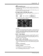
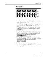
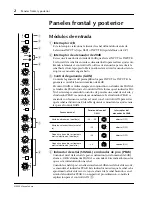
Страница 6: ...ts frequently lower the GAIN control to prevent the signal from distorting The following table shows usual settings for the GAIN control 4 SIGNAL indicator and PEAK indicator When the post EQ signal level nominal level 0dB reaches 10dB the SIG NAL indicator will light This indicator indicates that a signal is being input When the post EQ signal level reaches 3dB before clipping level the PEAK indi...
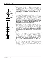
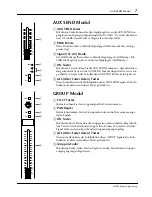
Страница 7: ...ypassing the EQ when it is not being used this switch pro vides a convenient way to compare the equalized and unequalized signals 7 AUX 1 AUX 2 controls These adjust the signal level that is sent to each output AUX SEND 1 and AUX SEND 2 These signals are pre fader i e they are taken from before the fader adjustment Nominal level is at 3 o clock position 8 AUX 3 AUX 4 AUX 5 controls These adjust th...
Страница 8: ...ed in the input module is on Be sure to turn off input modules that are not in use Even when a module is off the SIGNAL and PEAK indicators will light if a signal is being input You can also use the PFL switch to monitor the sig nal even if a module is off B PFL switch PFL is an acronym for Pre Fader Listen This switch allows you to monitor the signal of the input module regardless of the fader po...
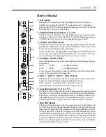
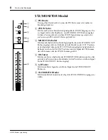
Страница 9: ...en the knob is in the center position 5 AUX 1 AUX 2 AUX 3 AUX 4 switches These switches send the mono signal to the AUX buses They are on when pressed in ST1 and ST2 select the AUX 1 and AUX 2 buses ST3 and ST4 select the AUX 3 and AUX 4 buses 6 Assign switches 1 2 3 4 ST These switches assign the signal of the stereo module to the group outputs and the ST output The PAN control located below adju...
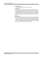
Страница 10: ... if a signal is being input You can also use the PFL switch to monitor the signal even if a module is off 0 PFL switch PFL is an acronym for Pre Fader Listen This switch allows you to monitor the signal of the stereo module regardless of the fader position the settings of the ON switch the group assign switches or the AUX settings As the name suggests the signal is taken pre fader post EQ You may ...
Страница 11: ...ed on When off no signal will be output from the corresponding AUX SEND jack 5 AFL After Fader Listen switch This monitors the AUX SEND signal This is on when the switch is pressed in GROUP module 1 TO ST switch This sends the GROUP signal to the stereo bus 2 PAN control This adjusts the panning of the signal sent to the stereo bus 3 ON switch This switch turns the GROUP on off The group is on whe...
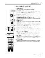
Страница 12: ...hat is output to the ST2 MONI OUT jack When the switch is in the ST2 position the signal will be the same as the signal that is sent to the ST1 OUT jack When the switch is in the MONI position the signal will be taken from the PFL bus AFL bus or the 2TR IN jack 4 ON switch This switch turns the ST2 MONITOR module on off When the switch is pressedinthemoduleison Whenthemoduleisoff nosignalwillbeout...
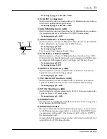
Страница 13: ...senttotheoutputdestinationselectedbytheassignswitchlocated above 7 Headphone jack PHONES control This is a 1 4 stereo phone jack for connecting a set of stereo headphones Headphones connected here can be used to monitor PFL AFL and the 2TR IN signals 8 REC OUT TAPE IN controls The REC OUT control adjusts the output signal level of the REC OUT jack The TAPE IN control adjusts the input signal level...
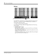
Страница 14: ...at the output level is 3dB before clipping 1 METER SELECT switch This switch selects whether GROUP 3 4 or ST2 MONITOR L R will be monitored Whentheswitchisnotpressedin thecentralmetergroupwillindicate the GROUP 3 4 signal level When the switch is pressed in the central meter group will indicate the ST2 MONITOR L R signal level GROUP1 GROUP2 GROUP3 GROUP4 L R ST2 MONITOR L R STEREO1 METER SELECT PE...
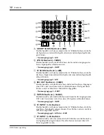
Страница 15: ...hich input the signal for each input module Use the A B switch to select these jacks These are balanced TRS jacks with tip hot ring cold and sleeve ground Nominal input level 60dB 3 INPUT INSERT I O jacks 0dB These are 1 4 phone jacks patched in front of the input module faders These are unbalanced TRS jacks with tip out ring in and sleeve ground Nominal input level 0dB Nominal output level 0dB 4 ...
Страница 16: ... stereo cassette deck or CD player Nominal input level 10dBV 0 ST INPUT 1 2 A jacks These are unbalanced 1 4 phone jacks which input a stereo source These jacks are selected by the A B switch Nominal input level 4dB or 10dB A ST INPUT 1 2 B jacks TheseareRCApinjackswhichinputastereosource Thesejacksareselected by the A B switch Nominal input level 4dB or 10dB Phantom Power Warning To prevent hazar...
Страница 17: ...d Nominal output level 0dB Nominal input level 0dB F GROUP OUT jacks 4dB These are unbalanced 1 4 jacks which output the signals of the GROUP buses Nominal output level 4dB G ST2 MONI OUT jacks 4dB These are unbalanced 1 4 jacks which output the signal of the STEREO L R bus or the signal of the MONITOR bus Nominal output level 4dB H ST1 OUT jacks 4dB These are balanced XLR3 32 type jacks which out...
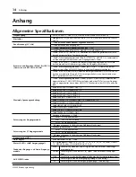
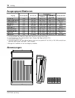
Страница 18: ...aster fader and the PFL switch on for one module and the MONI ST2 switch in the MONI position Maximum voltage gain 84dB INPUT A B STEREO OUT 1 2 84dB INPUT A B GROUP OUT 1 4 80dB INPUT A B AUX SEND 1 2 90dB INPUT A B AUX SEND 3 5 28dB TAPE IN STEREO OUT 1 2 30dB ST INPUT 1 4 STEREO OUT 1 2 GROUP OUT 1 4 30dB ST INPUT 1 4 AUX SEND 1 4 10dB GROUP SUB IN GROUP OUT 10dB ST SUB IN STEREO OUT 22dB 2TR I...
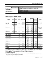
Страница 19: ...h GAIN Control Actual Load Impedance For Use with Nominal Input level Mixer Connector Sensitivity 1 Nominal Max Before Clip INPUT A B 60 4k Ω 50 600 Ω mics 600 Ω lines 80dB 77 5µV 60dB 775µV 40dB 7 75mV XLR 3 31 type A Phone jack B 2 16 36dB 12 3mV 16dB 123mV 4dB 1 23V 20 16 16dB 123mV 4dB 1 23V 24dB 12 3V STEREO INPUT 1 2 4 5k Ω 600 Ω lines 12dB 195mV 4dB 1 23V 24dB 12 3V Phone jack 4 RCA switcha...
Страница 20: ...ines 4dB 1 23V 24dB 12 3V XLR 3 32 type 1 STEREO INSERT OUT L R 600 Ω 10k Ω lines 0dB 775mV 20dB 7 75V Phone jack TRS 2 ST2 MONI OUT L R 75 Ω 600 Ω lines 4dB 1 23V 20dB 7 75V Phone jack 3 REC OUT L R 600 Ω 10k Ω lines 10dBV 316mV 16dBV 6 31V RCA GROUP 1 4 75 Ω 600 Ω lines 4dB 1 23V 20dB 7 75V Phone jack 3 AUX SEND 1 5 75 Ω 600 Ω lines 4dB 1 23V 20dB 7 75V Phone jack 3 INPUT INSERT OUT 600 Ω 10k Ω ...
Страница 21: ...CONSOLES DE MIXAGE MANUEL D UTILISATION Français ...
Страница 22: ...ommager l appareil Maniez le avec prudence 4 N ouvrez pas le boîtier et n essayez pas de réparer ou modifier l appareil vous même Ce produit ne contient aucune pièce que vous pourriez réparer remplacer Veuillez consulter un service après venteYamaha qualifié L ouverture du boîtier et ou toute tentative de toucher aux circuits internes annule la garantie 5 Coupez toujours l alimentation avant de pr...
Страница 23: ...entrée mono vous disposez de 4 jeux de canaux d entrée stéréo dotés des fonction suivantes Quatre entrées stéréo avec égalisation à deux bandes Commutateur d assignation GROUP AUX ST Commande de balance pan Commutateur de sélection prise d entrée TRS 1 4 et prise RCA unique ment pour entrée stéréo 1 2 La section master offre les caractéristiques suivantes Cinq commandes AUX SEND de type curseur In...
Страница 24: ...Si ce dernier témoin s allume souvent diminuez le GAIN pour éviter toute distorsion du signal Le tableau suivant vous données les réglages habituels pour la com mande GAIN 4 Témoin SIGNAL et témoin PEAK Lorsque le niveau du signal après égalisation niveau nominal 0dB atteint 10dB le témoin SIGNAL s allume Ce témoin indique qu un signal entre Lorsque le niveau du signal après égalisation atteint 3d...
Страница 25: ... seu lement de contourner l égaliseur lorsqu il n est pas utilisé mais en plus il vous permet de comparer facilement les signaux égalisés et non égalisés 7 Commandes AUX 1 AUX 2 Ces commandes règlent le niveau du signal envoyé à chaque sortie AUX SEND1etAUXSEND2 Cessignauxsontprisavant curseur cequisignifie qu ils sont pris avant de subir les réglages du curseur Le niveau nominal est obtenu avec u...
Страница 26: ...ve et désactive un module d entrée Lorsque l interrup teurestenfoncé lemoduleestactivé On Veillezàcouperlesmodulesdont vous n avez pas besoin Même lorsque le module est coupé les témoins SIGNAL et PEAK s allumeront si un signal entre Vous pouvez également vous servir du commutateur PFL pour écouter le signal fonction solo B Commutateur PFL PFL représente Pre Fader Listen ou écoute avant curseur Ce...
Страница 27: ...Commutateurs AUX 1 AUX 2 AUX 3 AUX 4 Ces commutateurs envoient le signal mono aux bus AUX Ils sont activés lorsque vous les enfoncez ST1 et ST2 sélectionnent les bus AUX 1 et AUX 2 ST3 et ST4 sélectionnent les bus AUX 3 et AUX 4 6 Commutateurs d assignation 1 2 3 4 ST Ces commutateurs assignent le signal du module d entrée aux sorties GROUPetàlasortieST LacommandePAN situéejusteen dessous permet d...
Страница 28: ...module est coupé les témoins SIGNAL et PEAK s allumeront si un signal entre Vous pouvez également vous servir du commutateur PFL pour écouter le signal fonction solo 0 Commutateur PFL PFL représente Pre Fader Listen ou écoute avant curseur Ce commutateur vous permet d écouter le signal entré dans le module indépendamment de la position du curseur ou des réglages AUX Comme le nom l indique le signa...
Страница 29: ... le bus est désactivé aucun signal ne sera envoyé via le jack AUX SEND correspondant 5 Commutateur AFL After Fader Listen Active la fonction solo du signal AUX SEND signal La fonction est activée lorsque le commutateur est enfoncé Module GROUP 1 Commutateur TO ST Envoie le signal GROUP au bus stéréo 2 Commande PAN Elle vous permet de déterminer la position stéréo du signal du bus stéréo 3 Interrup...
Страница 30: ...gnal qui est envoyé à la borne ST2 MONI OUT Lorsque le commutateur est en position ST2 le signal sera le même que le signal envoyé à la borne ST1 OUT Lorsque le commutateur est en position MONI le signal du bus PFL du bus AFL ou du bus 2TR IN sera choisi 4 Interrupteur ON Cet interrupteur active et désactive le module ST2 MONITOR Lorsque l interrupteur est enfoncé le module est activé On Lorsque l...
Страница 31: ... le signal Talkback sera envoyé au bus sélectionné avec les commutateurs d assigna tion situés au dessus 7 Borne pour casque Commande PHONES Il s agit d une borne jack stéréo 1 4 permettant de brancher un casque sté réo Ce casque peut alors servir pour écouter les signaux PFL AFL et 2TR IN 8 Commandes REC OUT TAPE IN La commande REC OUT règle le niveau de sortie du signal de la borne REC OUT La co...
Страница 32: ...tplusqu à3 dB du niveau de saturation 1 Commutateur METER SELECT Ce commutateur vous permet de choisir le signal contrôlé par les indica teurs GROUP 3 4 ou ST2 MONITOR L R Lorsque le commutateur n est pas enfoncé les deux indicateurs cen traux affichent le niveau du signal GROUP 3 4 Lorsquelecommutateurestenfoncé lesindicateurscentrauxaffichent le niveau du signal ST2 MONITOR L R GROUP1 GROUP2 GRO...
Страница 33: ...rises jacks 1 4 par où entre le signal d entrée de chaque module Utilisez le commutateurA B pour sélectionner ces bornes Ce sont des jacks symétriques TRS pointe chaud anneau froid gaine masse Niveau d entrée nominal 60dB 3 Bornes INPUT INSERT I O 0dB Il s agit de bornes jacks 1 4 qui se trouvent devant les curseurs des modules d entrée Ce sont des jacks asymétriques TRS pointe chaud anneau froid ...
Страница 34: ...qu un DAT un enregistreur à cassette ou un lecteur de CD Niveau d entrée nominal 10dBV 0 Bornes ST INPUT 1 2 A Il s agit de bornes jacks asymétriques 1 4 par où entre un signal stéréo Uti lisez le commutateur A B pour sélectionner ces bornes Niveau d entrée nominal 4dB ou 10dB A Bornes ST INPUT 1 2 B Il s agit de prises RCA par où entre un signal d une source sonore stéréo Uti lisez le commutateur...
Страница 35: ...ie nominal 0dB Niveau d entrée nominal 0dB F Bornes GROUP OUT 4dB Il s agit de bornes jacks asymétriques 1 4 qui envoient les signaux des bus GROUP Niveau de sortie nominal 4dB G Bornes ST2 MONI OUT 4dB Il s agit de bornes jacks asymétriques 1 4 qui envoient les signaux du bus STEREO L R ou le signal du bus MONITOR Niveau de sortie nominal 4dB H Borne ST1 OUT 4dB Il s agit de bornes symétriques de...
Страница 36: ...T2 MONITOR e le commutateur PFL activé pour un module et le commuta teur MONI ST2 en position MONI Gain de tension maximum 84dB INPUT A B STEREO OUT 1 2 84dB INPUT A B GROUP OUT 1 4 80dB INPUT A B AUX SEND 1 2 90dB INPUT A B AUX SEND 3 5 28dB TAPE IN STEREO OUT 1 2 30dB ST INPUT 1 4 STEREO OUT 1 2 GROUP OUT 1 4 30dB ST INPUT 1 4 AUX SEND 1 4 10dB GROUP SUB IN GROUP OUT 10dB ST SUB IN STEREO OUT 22...
Страница 37: ...2 596 mm Connexion d entrée Comm utateur PAD Comma nde GAIN Impedance de charge effective Pour niveau nominal Niveau d entrée Type de connecteur Sensibilité 1 Nominal Max avant saturation INPUT A B 60 4k Ω 50 600 Ω micro 600 Ω Ligne 80dB 77 5µV 60dB 775µV 40dB 7 75mV XLR 3 31 A Jack B 2 16 36dB 12 3mV 16dB 123mV 4dB 1 23V 20 16 16dB 123mV 4dB 1 23V 24dB 12 3V STEREO INPUT 1 2 4 5k Ω 600 Ω Ligne 12...
Страница 38: ...eur Nominal Max avant satu ration ST1 OUT L R 150 Ω 600 Ω Ligne 4dB 1 23V 24dB 12 3V XLR 3 32 1 STEREO INSERT OUT L R 600 Ω 10k Ω Ligne 0dB 775mV 20dB 7 75V Jack TRS 2 ST2 MONI OUT L R 75 Ω 600 Ω Ligne 4dB 1 23V 20dB 7 75V Jack 3 REC OUT L R 600 Ω 10k Ω Ligne 10dBV 316mV 16dBV 6 31V RCA GROUP 1 4 75 Ω 600 Ω Ligne 4dB 1 23V 20dB 7 75V Jack 3 AUX SEND 1 5 75 Ω 600 Ω Ligne 4dB 1 23V 20dB 7 75V Jack 3...
Страница 39: ...MISCHPULTE BEDIENUNGSANLEITUNG Deutsch ...
Страница 40: ...l vermeiden 4 Niemals das Gehäuse öffnen Reparaturen und Modifikationen nicht selbst ausführen Das MX400 enthält keinerlei Teile die vom Anwender selbst gewartet werden dürfen Überlassen Sie alle War tungsarbeiten dem anerkannten Yamaha Kundendienst Beim Öffnen des Gehäuses erlischt der Garantiean spruch 5 Vor dem Anschließen ausschalten Schalten Sie dieses Gerät aus bevor Sie Kabel anschließen od...
Страница 41: ...n Aus Taster PFL Taster Meter für eine präzise Pegeleinstellung Neben den Mono Kanälen bietet das MX400 4 Stereo Eingangspaare die fol gendermaßen bestückt sind Vier Stereo Eingänge mit 2 Bandentzerrung GROUP AUX ST Zuordnungstaster Balance Pan Regler TRS 1 4 Klinken und RCA Eingangsbuchse mit Anwahlschalter aus schließlich für Stereo Eingang 1 2 Die Master Sektion bietet folgende Funktionen Fünf ...
Страница 42: ...n leuchten Wenn die PEAK Diode häufiger leuchtet müssen Sie den Eingangspegel reduzieren um Signalver zerrung zu vermeiden Bitte entnehmen Sie die empfohlenen GAIN Werte der folgenden Tabelle 4 SIGNAL Diode und PEAK Diode Sobald der hinter dem EQ Entzerrung abgegriffene Signalpegel Nennpe gel 0dB die 10dB Marke erreicht leuchtet die SIGNAL Diode Diese Diode besagt daß an dem Eingang ein Signal anl...
Страница 43: ...nt zerrung aus der Signalkette nehmen wenn Sie sie nicht brauchen erlaubt Ihnen dieser Taster A B Vergleiche zwischen dem bearbeiteten und dem Originalsignal vorzunehmen 7 AUX 1 AUX 2 Regler Mit diesen Reglern können Sie den Pegel des an die AUX SEND 1 und AUX SEND 2 Summe angelegten Signals einstellen Beide Summen liegen vor dem Kanalfader der Kanalpegel übt also keinerlei Einfluß aus Die 3 Uhr E...
Страница 44: ... Taster Mit diesem Taster können Sie das Modul zu und abschalten Wenn der Taster gedrückt ist ist das betreffende Modul eingeschaltet Module die Sie in einer bestimmten Situation nicht brauchen sollten Sie auf jeden Fall aus schalten Selbst wenn ein Modul ausgeschaltet ist leuchten die SIGNAL und PEAK Diode sobald ein Signal an das Modul angelegt wird Außerdem kön nen Sie das Signal abhören indem ...
Страница 45: ...AUX 1 AUX 2 AUX 3 AUX 4 Taster Mit diesem Taster ordnen Sie das Mono Signal der entsprechenden AUX Summe zu Die Zuordnung erfolgt bei gedrücktem Taster ST1 und ST2 Anwahl der AUX 1 und AUX 2 Summe ST3 und ST4 Anwahl der AUX 3 und AUX 4 Summe 6 Zuordnungstaster 1 2 3 4 ST Mit diesen Tastern ordnen Sie das an das Eingangsmodul angelegte Signal den GROUP sowie dem ST Ausgang zu Mit dem darunter befin...
Страница 46: ...schaltet ist leuchten die SIGNAL und PEAK Diode sobald ein Signal an das Modul angelegt wird Außerdem kön nen Sie das Signal abhören indem Sie den PFL Taster drücken Solofunk tion 0 PFL Taster PFL ist die Abkürzung für Pre Fader Listen vor dem Fader abhören Mit diesem Taster können Sie das an einem Eingangsmodul anliegende Signal jederzeit abhören ganz gleich wie der Fader der ON Taster die Gruppe...
Страница 47: ...Signal an 5 AFL After Fader Listen Taster DientzumAktivierenderSolofunktiondiesesAUXSENDSignals DieSolo funktion ist aktiv wenn dieser Taster gedrückt ist GROUP Modul 1 TO ST Taster Hiermit ordnen Sie das Gruppensignal der Stereosumme zu 2 PAN Regler Hiermit bestimmen Sie die Stereoposition des an die Stereosumme ange legten Signals 3 ON Taster MitdiesemTasterkönnenSiedieGruppeein undausschalten B...
Страница 48: ...T2 MONIOUT Buchse angelegt wird an Befindet sich der Schalter in der ST2 Position ist das Signal mit dem an die ST1 OUT Buchse angelegten Signal identisch Befindet er sich in der MONI Position wird das Signal der PFL Summe der AFL Summe oder der 2TR IN Summe gewählt 4 ON Taster Mit diesem Taster schalten Sie das ST2 MONITOR Modul ein und aus Bei gedrücktem Taster ist dieses Modul aktiv Ist der Tas...
Страница 49: ... Zuordnungsta stern siehe oben gewählte Summe angelegt 7 Kopfhörerbuchse PHONES Regler An diese 1 4 Stereo Klinkenbuchse können Sie einen Stereo Kopfhörer anschließen mit dem die PFL AFL und 2TR IN Signale überwacht werden können 8 REC OUT TAPE IN Regler Mit dem REC OUT Regler können Sie den Pegel des an die REC OUT Buchse angelegten Signals einstellen Mit dem TAPE IN Regler können Sie den Pegel d...
Страница 50: ...r der Verzerrungs grenze befindet 1 METER SELECT Taster Mit diesem Taster ordnen Sie entweder das GROUP 3 4 oder ST2 MONI TOR L R Signal den Metern zu Ist dieser Taster nicht gedrückt zeigen die beiden mittleren Meter den Signalpegel von Gruppe 3 4 an Ist der Taster gedrückt zeigen die beiden mittleren Meter den Signal pegel der ST2 MONITOR L R Summe an GROUP1 GROUP2 GROUP3 GROUP4 L R ST2 MONITOR ...
Страница 51: ...n die die Signalquelle der Eingangsmodule angelegt werden muß Diese Buchsen müssen mit dem A B Taster angewählt werden Es sind symmetrische TRS Buchsen mit fol gender Belegung Spitze heiß Ring kalt Mantel Masse Nenneingangspegel 60dB 3 INPUT INSERT I O Buchsen 0dB Hierbei handelt es sich um 1 4 Klinkenbuchsen die sich vor den Fadern derEingangsmodulebefinden EssindasymmetrischeTRSBuchsenmitfol gen...
Страница 52: ...er abgegriffen Nennausgangspegel 10dBV 9 TAPE IN Buchsen 10dBV HierbeihandeltessichumRCABuchsen mitdenenSiedieAusgängeneines DAT oder Cassettenrecorders bzw eines CD Spielers verbinden können Nenneingangspegel 10dBV 0 ST INPUT 1 2 A Buchsen Hierbei handelt es sich um asymmetrische 1 4 Klinkenbuchsen an die Sie eine Stereo Signalquelle anlegen können Diese Buchsen müssen mit dem A B Taster angewähl...
Страница 53: ...eiß Ring kalt Mantel Masse Nennausgangspegel 0dB Nenneingangspegel 0dB F GROUP OUT Buchsen 4dB Hierbei handelt es sich um asymmetrische 1 4 Buchsen an denen das Signal der entsprechenden Gruppe anliegt Nennausgangspegel 4dB G ST2 MONI OUT Buchsen 4dB Hierbei handelt es sich um asymmetrische 1 4 Buchsen an denen das Signal der STEREO L R Summe bzw der MONITOR Summe anliegt Nennausgangspegel 4dB H S...
Страница 54: ...Master Fader wobei der PFL Taster eines Eingangs moduls eingeschaltet war und der MONI ST2 Schalter sich in der MONI Position be fand Maximale Spannungsanhebung 84dB INPUT A B STEREO OUT 1 2 84dB INPUT A B GROUP OUT 1 4 80dB INPUT A B AUX SEND 1 2 90dB INPUT A B AUX SEND 3 5 28dB TAPE IN STEREO OUT 1 2 30dB ST INPUT 1 4 STEREO OUT 1 2 GROUP OUT 1 4 30dB ST INPUT 1 4 AUX SEND 1 4 10dB GROUP SUB IN ...
Страница 55: ... 180 2 596 mm MX400 16 802 180 2 596 mm MX400 24 1042 180 2 596 mm Eingänge PAD Taster GAIN Regler Lastim pedanz Bei Nennwert Eingangspegel Anschluß Empf 1 Nennwert Max vor Verzerrung INPUT A B 60 4k Ω 50 600 Ω Mikrof 600 Ω Line 80dB 77 5µV 60dB 775µV 40dB 7 75mV XLR 3 31 A Klinke B 2 16 36dB 12 3mV 16dB 123mV 4dB 1 23V 20 16 16dB 123mV 4dB 1 23V 24dB 12 3V STEREO INPUT 1 2 4 5k Ω 600 Ω Line 12dB ...
Страница 56: ...vor Verzerrung ST1 OUT L R 150 Ω 600 Ω Line 4dB 1 23V 24dB 12 3V XLR 3 32 1 STEREO INSERT OUT L R 600 Ω 10k Ω Line 0dB 775mV 20dB 7 75V Klinke TRS 2 ST2 MONI OUT L R 75 Ω 600 Ω Line 4dB 1 23V 20dB 7 75V Klinke 3 REC OUT L R 600 Ω 10k Ω Line 10dBV 316mV 16dBV 6 31V RCA GROUP 1 4 75 Ω 600 Ω Line 4dB 1 23V 20dB 7 75V Klinke 3 AUX SEND 1 5 75 Ω 600 Ω Line 4dB 1 23V 20dB 7 75V Klinke 3 INPUT INSERT OUT...
Страница 57: ...CONSOLA DE MEZCLA MANUAL DE USO Español ...
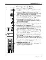
Страница 58: ...ntente reparar ni modificar usted mismo la unidad Este producto no contiene componentes que pueda reparar el usuario Solicite todo el mantenimiento al per sonal de servicio cualificado de Yamaha Si abre la caja y o modifica los circuitos internos se anulará la garantía 5 Antes de realizar las conexiones desconecte siempre la alimentación Antes de conectar o desconectar los cables desconecte siempr...
Страница 59: ...tradas estéreo con ecualizador EQ de 2 bandas Interruptor de asignación de grupo auxiliar estéreo GROUP AUX ST Control de equilibrio panoramización Selector de toma telefónica TRS de 1 4 y toma de entrada RCA solamente para entrada estéreo 1 2 La sección principal proporciona las funciones siguientes Cinco controles de transmisión auxiliar AUX SEND tipo regulador de nivel Medidor de nivel de 3 pun...
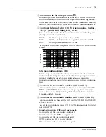
Страница 60: ...ia reduzca el nivel con el control GAIN para evitar que la señal se distorsione En la tabla siguiente se muestran los ajustes usua les para el control GAIN 4 Indicador de señal SIGNAL e indicador de pico PEAK Cuando el nivel de la señal de post ecualización nivel nominal de 0dB alcance 10dB el indicador SIGNAL se encenderá Este indicador muestra que se está introduciendo una señal Cuando la señal ...
Страница 61: ...l interruptor esté enganchado Además para poner en deri vación el ecualizador cuando no esté utilizándose este interruptor proporcionaunaformamuyútildecompararseñalesecualizadasysinecua lizar 7 Controles de transmisión auxiliar AUX 1 AUX 2 Estos controles ajustan el nivel de la señal que se envía a cada salida AUX SEND 1 y AUX SEND 2 Estas señales son de pre regulación de nivel es decir se toman a...
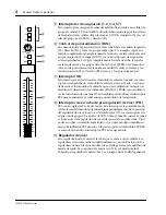
Страница 62: ...ulos de entrada que no esté utilizando Aunque un módulo esté desactivado los indicadores SIGNAL y PEAK se encenderán si se está introduciendo una señal Usted también podrá utilizar el interruptor PFL para monitorizar la señal aunque un módulo esté desactivado B Interruptor de escucha de pre regulación de nivel PFL PFL son las siglas de Pre Fader Listen Este interruptor le permitirá moni torizar la...
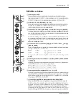
Страница 63: ... tipo aplanamiento de 15dB LOW 80 Hz tipo aplanamiento de 15dB La respuesta en frecuencia será plana cuando el mando esté en la posición central 5 Interruptores de transmisión auxiliar AUX 1 AUX 2 AUX 3 AUX 4 Estos interruptores envían la señal monoaural a los busesAUX Estarán acti vados ON cuando se encuentren enganchados ST1 y ST2 seleccionan los buses AUX 1 y AUX 2 ST3 y ST4 seleccionan los bus...
Страница 64: ...tivado los indicadores SIGNAL y PEAK se encenderán si se está introduciendo una señal Usted también podrá utilizar el interruptor PFL para monitorizar la señal aunque un módulo esté desactivado 0 Interruptor de escucha de pre regulación de nivel PFL PFL son las siglas de Pre Fader Listen Este interruptor le permitirá moni torizar la señal del módulo de entrada independientemente de la posición del...
Страница 65: ...o saldrá señal a través de la toma AUX SEND correspondiente 5 Interruptor de escucha post regulador de nivel AFL Monitoriza la señal deAUX SEND Estará activado ON cuando se encuen tre enganchado Grupo MODULE 1 Interruptor a estéreo TO ST Este interruptor envía la señal de GROUP al bus estéreo 2 Control de panoramización PAN Este control ajusta la panoramización de la señal enviada al bus estéreo 3...
Страница 66: ...or selecciona la señal que sale a la toma ST2 MONI OUT Cuando el interruptor esté en la posición ST2 la señal será la misma que la señal que se transmite a la toma ST1 OUT Cuando el interruptor esté en la posición MONI la señal se tomará del bus PFL el bus AFL o la toma 2TR IN 4 Interruptor ON Este interruptor activa desactiva el módulo ST2 MONITOR El módulo estará activado ON cuando se encuentre ...
Страница 67: ...comunicación Cuando lo enga nche la señal de intercomunicación se enviará al destino de salida seleccio nado con el interruptor de asignación situado arriba 7 Toma para auriculares control de auriculares PHONES Ésta es una toma telefónica estéreo de 1 4 para conectar un juego de auric ulares estéreo Los auriculares conectados aquí podrán utilizarse para mon itorizar las señales PFL AFL y 2TR IN 8 ...
Страница 68: ...e salida es 3dB antes del recorte 1 Selector METER SELECT Este selector la monitorización de GROUP 3 4 o ST2 MONITOR L R Cuando no haya presionado en el grupo de medidores centrales indi cará el nivel de la señal de GROUP 3 4 Cuando haya presionado el interruptor en el grupo de medidores cen trales indicará el nivel de la señal de ST2 MONITOR L R GROUP1 GROUP2 GROUP3 GROUP4 L R ST2 MONITOR L R STE...
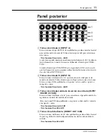
Страница 69: ...a módulo de entrada Utilice el interruptor A B para seleccionar estas tomas Éstas son tomas TRS equilibradas con punta activo anillo pasivo y manguito masa Nivel nominal de entrada 60dB 3 Tomas de entrada salida de inserción de entrada INPUT INSERT I O 0dB Éstas son tomas telefónicas de 1 4 para conexión en el panel frontal de los reguladores de nivel del módulo de entrada Éstas son tomas TRS dese...
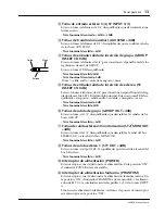
Страница 70: ...inal de salida 10dBV 9 Tomas de entrada de cinta TAPE IN 10dBV Éstas son tomas RCA que dan entrada a una fuente estéreo como un graba dor de cinta audiodigital DAT un grabador de cassettes o un reproductor de discos compactos CD Nivel nominal de entrada 10dBV 0 Tomas A de entrada estéreo 1 2 ST INPUT 1 2 A Éstas son tomas telefónicas de 1 4 desequilibradas que dan entrada a una fuente estéreo Esta...
Страница 71: ... anillo entrada y manguito masa Nivel nominal de entrada 0dB Nivel nominal de salida 0dB F Tomas de salida de grupo GROUP OUT 4dB Éstas son tomas de 1 4 desequilibradas que dan salida a las señales de los buses GROUP Nivel nominal de salida 4dB G Tomasdesalidaestéreo2 monitorización ST2 MONIOUT 4dB Éstas son tomas de 1 4 desequilibradas que dan salida a la señal del bus STEREO L R o a la señal del...
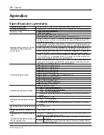
Страница 72: ...r MONI ST2 en la posición MONI 64dB relación señal ruido 68dB STEREO 2 MONITOR Medición realizada con el regulador de nivel principal ST2 MONITOR y el interruptor PFL enganchado ON para un módulo y el interruptor MONI ST2 en la posición MONI Ganancia máxima de tensión 84dB INPUT A B STEREO OUT 1 2 84dB INPUT A B GROUP OUT 1 4 80dB INPUT A B AUX SEND 1 2 90dB INPUT A B AUX SEND 3 5 28dB TAPE IN STE...
Страница 73: ...r PAD Contr ol GAIN Impedancia de carga actual Para utilizar con el valor nominal Nivel de entrada Conector de mezclador Sensibilidad 1 Nominal Máx antes del recorte INPUT A B 60 4k Ω Micrófonos de 50 600 Ω y líneas de 600 Ω 80dB 77 5µV 60dB 775µV 40dB 7 75mV Tipo XLR 3 31 A toma telefónica B 2 16 36dB 12 3mV 16dB 123mV 4dB 1 23V 20 16 16dB 123mV 4dB 1 23V 24dB 12 3V STEREO INPUT 1 2 4 5k Ω Líneas...
Страница 74: ... Dimensiones Conexión de salida Impedancia de la fuente actual Para utilizar con el valor nominal Nivel de salida Conector de mezclador Nominal Máx antes del recorte ST1 OUT L R 150 Ω Líneas de 600 Ω 4dB 1 23V 24dB 12 3V Tipo XLR 3 32 1 STEREO INSERT OUT L R 600 Ω Líneas de 10 kΩ 0dB 775mV 20dB 7 75V Toma telefónica TRS 2 ST2 MONI OUT L R 75 Ω Líneas de 600 Ω 4dB 1 23V 20dB 7 75V Toma telefónica 3...
Страница 75: ...METER ST2 MONI OUT 4dB AFL CTRL AFL PFL CTRL R AUX L 5 4 3 1 2 GROUP 4 3 2 1 SUM INV SUM LA SUM L INV LA AFL TO ST PAN ON METER LA GROUP INSERT I O 0dB 1 4 EQ PRE ON PFL AUX 5 AUX 4 AUX 3 AUX 2 AUX 1 10 4 SIGNAL PEAK BAL PAN PEAK SIGNAL EQ EQ HIGH LOW PAD HA HA PAD DIRECT OUT 0dB 1 BA INPUT INSERT I O 0dB 1 8 12 16 24 INPUT B 1 B A HPF 80 MID FREQ HIGH EQ EQ 20dB GAIN INPUT A 1 INPUT A PHANTOM MID...
Страница 76: ...YAMAHA CORPORATION R0 1 IP Printed in Korea P O Box 1 Hamamatsu Japan ...