


MG10/2
17
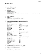
1.
Measurement conditions
1-1.
Environment
Normal temperature (10 to 35C)
Normal humidity (45 to 85%)
1-2.
Power Source
The voltage is /-10%.
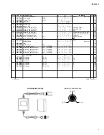
AC Adaptor (PA-10) shall be used.
WC703600 (H,W:230V) or WC703500 (U,V:120V), WC703700 (B:230V), WC703800 (K:220V), WC703900 (A:240V),
WC711000 (O:220V)
2.
Electric characteristics
2-1.
Preparation
The load resistances for each output terminals are as follows,
PHONES (L/ R):
40 ohms
Others:
10 kohms
2-2.
Unless otherwise specified, the operation elements shall be set as follows,
• CH (1-2) INPUT
GAIN control
MAX(-60dBu)
80 switch
OFF
EQ (HIGH, MID, LOW) level control
CENTER
AUX level control
PRE(turned counterclockwise fully)
PAN control
L(turned counterclockwise fully)
CH LEVEL VR
MAX
• ST CH (3/4, 5/6)
GAIN control
MIC:MAX(-60dBu)
80 switch
OFF
EQ (HIGH, MID, LOW) level control
CENTER
AUX level control
PRE(turned counterclockwise fully)
PAN/BAL control
L(turned counterclockwise fully)
CH LEVEL VR
MAX
• ST CH (7/8, 9/10)
EQ (HIGH, MID, LOW) level control
CENTER
AUX level control
PRE(turned counterclockwise fully)
BAL control
L(turned counterclockwise fully)
CH LEVEL VR
MAX
• MASTER control
RETURN to ST level control
MAX
2TR IN to ST level control
MAX
C-R/PHONES level control
MAX
ST Master VR
MAX
• Others
PHANTOM switch
OFF
2-3.
Unless otherwise specified, the input signal shall be 1kHz sine wave.
2-4.
The input signal impedance shall be 150 ohms.
2-5.
Indicator Inspection
POWER LED shall light when the unit is turned on.
■
INSPECTIONS