


SELF-DIAGNOSTIC FUNCTION AND DIAGNOSTIC CODE TABLE
9-5
EAS1SD1039
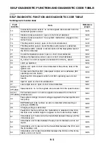
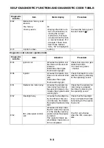
SELF-DIAGNOSTIC FUNCTION AND DIAGNOSTIC CODE TABLE
Self-diagnostic function table
Fault
code No.
Item
Reference
pages
12
Crankshaft position sensor: no normal signals are received from the
crankshaft position sensor.
13
Intake air pressure sensor: open or short circuit detected.
14
Intake air pressure sensor: hose system malfunction (clogged or de-
tached hose).
15
Throttle position sensor: open or short circuit detected.
16
Throttle position sensor: stuck throttle position sensor is detected.
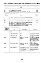
19
Sidestand switch: a break or disconnection of the blue/yellow lead of
the ECU is detected.
21
Coolant temperature sensor: open or short circuit detected.
22
Intake air temperature sensor: open or short circuit detected.
24
O
2
sensor: no normal signals are received from the O
2
sensor.
30
Latch up detected.
33
Ignition coil: open or short circuit detected in the primary lead of the
ignition coil.
37
Component other than ISC (idle speed control) unit is defective (ISC
operating sound is heard).
Defective ISC (idle speed control) unit (ISC operating sound is not
heard).
39
Injector: open or short circuit detected.
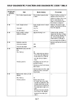
41
Lean angle sensor: open or short circuit detected.
42 (for
YP125R)
Speed sensor: no normal signals are received from the speed sensor.
42 (for
YP125RA)
Front wheel sensor: no normal signals are received from the front
wheel sensor.
43
Fuel system voltage: incorrect voltage supplied to the fuel injector and
fuel pump.
44
EEPROM fault code number: an error is detected while reading or
writing on EEPROM.
46
Charging voltage is abnormal.
50
Faulty ECU memory. (When this malfunction is detected in the ECU,
the fault code number might not appear on the multi-function meter.)
51
Immobilizer unit: Code cannot be transmitted between the key and the
immobilizer unit.
52
Immobilizer unit: Codes between the key and immobilizer unit do not
match.
53
Immobilizer unit: Codes cannot be transmitted between the ECU and
the immobilizer unit.
54
Immobilizer unit: Codes transmitted between the ECU and the immo-
bilizer unit do not match.
Содержание MBK XMAX 2014
Страница 1: ...2014 SERVICE MANUAL YP125R YP125RA 2DM F8197 E0 ...
Страница 6: ......
Страница 8: ......
Страница 64: ...TIGHTENING TORQUES 2 17 Muffler tightening sequence 1 2 3 ...
Страница 72: ...LUBRICATION SYSTEM DIAGRAMS 2 25 EAS2DM1116 LUBRICATION SYSTEM DIAGRAMS 1 2 3 4 5 3 ...
Страница 73: ...LUBRICATION SYSTEM DIAGRAMS 2 26 1 Camshaft 2 Crankshaft 3 Oil pump 4 Oil filter 5 Oil strainer ...
Страница 78: ...CABLE ROUTING 2 31 Steering head front view 1 2 3 4 5 6 8 8 A 7 7 ...
Страница 80: ...CABLE ROUTING 2 33 Front brake left side view for YP125R 1 2 2 1 1 2 2 D E A B C ...
Страница 82: ...CABLE ROUTING 2 35 Front brake left side view for YP125RA 2 1 1 2 1 2 2 A B D E C ...
Страница 84: ...CABLE ROUTING 2 37 Engine and rear brake left side and right side view for YP125R B 2 1 2 1 2 A A 3 3 C ...
Страница 86: ...CABLE ROUTING 2 39 Engine and rear brake left side and right side view for YP125RA 1 2 1 2 2 A A B 3 4 3 4 4 ...
Страница 92: ...CABLE ROUTING 2 45 Frame right side view 3 2 4 1 2 3 A B 6 5 3 A B 3 3 2 3 3 A A B A B B 3 ...
Страница 94: ...CABLE ROUTING 2 47 Engine right side view 6 6 6 6 C D C D D C 10 B 9 5 6 1 2 8 3 4 5 6 7 A ...
Страница 98: ...CABLE ROUTING 2 51 Frame left side view C D C D 2 1 E 1 2 D C 6 1 4 5 3 2 1 7 3 2 1 A B ...
Страница 100: ...CABLE ROUTING 2 53 Engine left side view 1 1 1 1 1 2 3 4 5 6 7 8 9 7 7 A B A B A B 1 ...
Страница 102: ...CABLE ROUTING 2 55 Frame top view 7 8 9 10 11 12 13 13 17 19 19 A D B C 14 C B 1 2 3 4 5 6 14 15 16 18 19 ...
Страница 104: ...CABLE ROUTING 2 57 Engine and frame top view 1 2 4 5 6 7 8 9 10 11 12 13 1 4 5 6 7 8 1 3 10 11 6 8 C 3 11 B A B A 3 ...
Страница 106: ...CABLE ROUTING 2 59 Rear brake right side view 2 2 2 2 2 2 1 1 2 3 A B C 3 ...
Страница 108: ...CABLE ROUTING 2 61 Hydraulic unit for YP125RA 3 2 1 2 3 3 2 2 3 2 2 2 3 3 3 4 4 1 1 4 2 6 B A A 5 1 5 1 5 ...
Страница 110: ...CABLE ROUTING 2 63 ...
Страница 228: ...REAR SHOCK ABSORBER ASSEMBLIES AND SWINGARM 4 89 ...
Страница 231: ......
Страница 291: ...CRANKSHAFT 5 60 a 1 ...
Страница 292: ...CRANKSHAFT 5 61 ...
Страница 302: ...WATER PUMP 6 9 ...
Страница 313: ......
Страница 329: ...CHARGING SYSTEM 8 16 2 AC magneto 3 Rectifier regulator 12 Battery 13 Main fuse 17 Frame ground ...
Страница 331: ...CHARGING SYSTEM 8 18 ...
Страница 349: ...COOLING SYSTEM 8 36 ...
Страница 391: ...FUEL PUMP SYSTEM 8 78 ...
Страница 400: ...IMMOBILIZER SYSTEM 8 87 a Light on b Light off ...
Страница 401: ...IMMOBILIZER SYSTEM 8 88 ...
Страница 405: ...ABS ANTI LOCK BRAKE SYSTEM for YP125RA 8 92 ...
Страница 439: ...ABS ANTI LOCK BRAKE SYSTEM for YP125RA 8 126 ...
Страница 464: ...ELECTRICAL COMPONENTS 8 151 ...
Страница 476: ......
Страница 477: ......
Страница 478: ......