


FUEL INJECTION SYSTEM
8-67
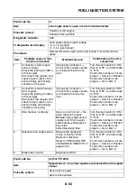
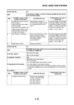
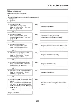
2
“01” is indicated in diagnostic
mode (Code No. D60). EEP-
ROM data error for adjust-
ment of CO concentration.
Change the CO concentra-
tion, and rewrite in EE-
PROM.
Refer to “ADJUSTING THE
EXHAUST GAS VOLUME”
on page 3-7.
After this adjustment is
made, the memory is not re-
covered when the main
switch is turned to “OFF”.
Turn the main switch to “ON”.
Fault code number is not dis-
played
→
Service is finished.
Fault code number is dis-
played
→
Repeat item 1. If
the same number is indicat-
ed, go to item 5.
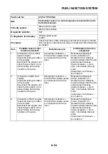
3
“03” is indicated in diagnostic
mode (Code No. D60). EEP-
ROM data error for immobi-
lizer code.
Turn the main switch to
“OFF”.
Turn the main switch to “ON”.
Fault code number is not dis-
played
→
Service is finished.
Fault code number is dis-
played
→
Repeat item 1. If
the same number is indicat-
ed, go to item 5.
4
“04” is indicated in diagnostic
mode (Code No. D60). EEP-
ROM data error for ISC (idle
speed control) unit learning
values.
Turn the main switch to “ON”,
and then fully opens and
closes the throttle valve.
Turn the main switch to
“OFF”.
Turn the main switch to “ON”.
Fault code number is not dis-
played
→
Service is finished.
Fault code number is dis-
played
→
Repeat item 1. If
the same number is indicat-
ed, go to item 5.
5
Malfunction in ECU.
Replace the ECU.
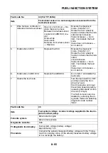
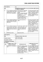
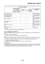
Fault code No.
46
Item
Charging voltage is abnormal.
Fail-safe system
Able to start engine
Able to drive vehicle
Diagnostic code No.
—
FI diagnostic tool display
—
Procedure
—
Item
Probable cause of mal-
function and check
Maintenance job
Confirmation of service
completion
1
Malfunction in charging sys-
tem.
Check the charging system.
Refer to “CHARGING SYS-
TEM” on page 8-15.
Defective rectifier/regulator
or AC magneto
→
Replace.
Defective connection in the
charging system circuit
→
Properly connect or replace
the wire harness.
Start the engine and let it idle
for approximately 5 seconds.
Fault code number is not dis-
played
→
Service is finished.
Fault code number is dis-
played
→
Repeat the mainte-
nance job.
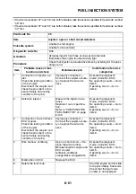
Fault code No.
44
Item
EEPROM fault code number: an error is detected while reading
or writing on EEPROM.
Содержание MBK XMAX 2014
Страница 1: ...2014 SERVICE MANUAL YP125R YP125RA 2DM F8197 E0 ...
Страница 6: ......
Страница 8: ......
Страница 64: ...TIGHTENING TORQUES 2 17 Muffler tightening sequence 1 2 3 ...
Страница 72: ...LUBRICATION SYSTEM DIAGRAMS 2 25 EAS2DM1116 LUBRICATION SYSTEM DIAGRAMS 1 2 3 4 5 3 ...
Страница 73: ...LUBRICATION SYSTEM DIAGRAMS 2 26 1 Camshaft 2 Crankshaft 3 Oil pump 4 Oil filter 5 Oil strainer ...
Страница 78: ...CABLE ROUTING 2 31 Steering head front view 1 2 3 4 5 6 8 8 A 7 7 ...
Страница 80: ...CABLE ROUTING 2 33 Front brake left side view for YP125R 1 2 2 1 1 2 2 D E A B C ...
Страница 82: ...CABLE ROUTING 2 35 Front brake left side view for YP125RA 2 1 1 2 1 2 2 A B D E C ...
Страница 84: ...CABLE ROUTING 2 37 Engine and rear brake left side and right side view for YP125R B 2 1 2 1 2 A A 3 3 C ...
Страница 86: ...CABLE ROUTING 2 39 Engine and rear brake left side and right side view for YP125RA 1 2 1 2 2 A A B 3 4 3 4 4 ...
Страница 92: ...CABLE ROUTING 2 45 Frame right side view 3 2 4 1 2 3 A B 6 5 3 A B 3 3 2 3 3 A A B A B B 3 ...
Страница 94: ...CABLE ROUTING 2 47 Engine right side view 6 6 6 6 C D C D D C 10 B 9 5 6 1 2 8 3 4 5 6 7 A ...
Страница 98: ...CABLE ROUTING 2 51 Frame left side view C D C D 2 1 E 1 2 D C 6 1 4 5 3 2 1 7 3 2 1 A B ...
Страница 100: ...CABLE ROUTING 2 53 Engine left side view 1 1 1 1 1 2 3 4 5 6 7 8 9 7 7 A B A B A B 1 ...
Страница 102: ...CABLE ROUTING 2 55 Frame top view 7 8 9 10 11 12 13 13 17 19 19 A D B C 14 C B 1 2 3 4 5 6 14 15 16 18 19 ...
Страница 104: ...CABLE ROUTING 2 57 Engine and frame top view 1 2 4 5 6 7 8 9 10 11 12 13 1 4 5 6 7 8 1 3 10 11 6 8 C 3 11 B A B A 3 ...
Страница 106: ...CABLE ROUTING 2 59 Rear brake right side view 2 2 2 2 2 2 1 1 2 3 A B C 3 ...
Страница 108: ...CABLE ROUTING 2 61 Hydraulic unit for YP125RA 3 2 1 2 3 3 2 2 3 2 2 2 3 3 3 4 4 1 1 4 2 6 B A A 5 1 5 1 5 ...
Страница 110: ...CABLE ROUTING 2 63 ...
Страница 228: ...REAR SHOCK ABSORBER ASSEMBLIES AND SWINGARM 4 89 ...
Страница 231: ......
Страница 291: ...CRANKSHAFT 5 60 a 1 ...
Страница 292: ...CRANKSHAFT 5 61 ...
Страница 302: ...WATER PUMP 6 9 ...
Страница 313: ......
Страница 329: ...CHARGING SYSTEM 8 16 2 AC magneto 3 Rectifier regulator 12 Battery 13 Main fuse 17 Frame ground ...
Страница 331: ...CHARGING SYSTEM 8 18 ...
Страница 349: ...COOLING SYSTEM 8 36 ...
Страница 391: ...FUEL PUMP SYSTEM 8 78 ...
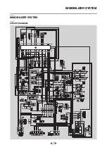
Страница 400: ...IMMOBILIZER SYSTEM 8 87 a Light on b Light off ...
Страница 401: ...IMMOBILIZER SYSTEM 8 88 ...
Страница 405: ...ABS ANTI LOCK BRAKE SYSTEM for YP125RA 8 92 ...
Страница 439: ...ABS ANTI LOCK BRAKE SYSTEM for YP125RA 8 126 ...
Страница 464: ...ELECTRICAL COMPONENTS 8 151 ...
Страница 476: ......
Страница 477: ......
Страница 478: ......