


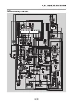


FUEL INJECTION SYSTEM
8-45
EAS27462
TROUBLESHOOTING DETAILS
This section describes the measures per fault code number displayed on the multi-function meter.
Check and service the items or components that are the probable cause of the malfunction following
the order given.
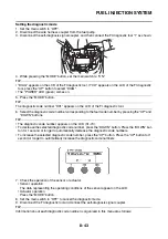
After the check and service of the malfunctioning part have been completed, reset the multi-function
meter according to the “Confirmation of service completion”.
Fault code No.:
Fault code number displayed on the multi-function meter when the engine failed to work normally.
Diagnostic code No.:
Diagnostic code number to be used when the diagnostic mode is operated. Refer to “SELF-DIAGNOS-
TIC FUNCTION AND DIAGNOSTIC CODE TABLE” on page 9-5.
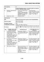
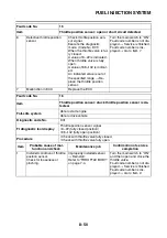
Fault code No.
12
Item
Crankshaft position sensor: no normal signals are received
from the crankshaft position sensor.
Fail-safe system
Unable to start engine
Unable to drive vehicle
Diagnostic code No.
—
FI diagnostic tool display
—
Procedure
—
Item
Probable cause of mal-
function and check
Maintenance job
Confirmation of service
completion
1
Connection of crankshaft po-
sition sensor coupler.
Check the locking condition
of the coupler.
Disconnect the coupler and
check the pins (bent or bro-
ken terminals and locking
condition of the pins).
Improperly connected
→
Connect the coupler secure-
ly or replace the wire har-
ness.
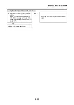
Crank the engine.
Fault code number is not dis-
played
→
Service is finished.
Fault code number is dis-
played
→
Go to item 2.
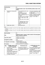
2
Connection of wire harness
ECU coupler.
Check the locking condition
of the coupler.
Disconnect the coupler and
check the pins (bent or bro-
ken terminals and locking
condition of the pins).
Improperly connected
→
Connect the coupler secure-
ly or replace the wire har-
ness.
Crank the engine.
Fault code number is not dis-
played
→
Service is finished.
Fault code number is dis-
played
→
Go to item 3.
3
Wire harness continuity.
Open or short circuit
→
Re-
place the wire harness.
Between crankshaft position
sensor coupler and ECU
coupler.
black/blue–black/blue
white/red–white/red
Crank the engine.
Fault code number is not dis-
played
→
Service is finished.
Fault code number is dis-
played
→
Go to item 4.
4
Installed condition of crank-
shaft position sensor.
Check for looseness or
pinching.
Improperly installed sensor
→
Reinstall or replace the
sensor.
Crank the engine.
Fault code number is not dis-
played
→
Service is finished.
Fault code number is dis-
played
→
Go to item 5.
Содержание MBK XMAX 2014
Страница 1: ...2014 SERVICE MANUAL YP125R YP125RA 2DM F8197 E0 ...
Страница 6: ......
Страница 8: ......
Страница 64: ...TIGHTENING TORQUES 2 17 Muffler tightening sequence 1 2 3 ...
Страница 72: ...LUBRICATION SYSTEM DIAGRAMS 2 25 EAS2DM1116 LUBRICATION SYSTEM DIAGRAMS 1 2 3 4 5 3 ...
Страница 73: ...LUBRICATION SYSTEM DIAGRAMS 2 26 1 Camshaft 2 Crankshaft 3 Oil pump 4 Oil filter 5 Oil strainer ...
Страница 78: ...CABLE ROUTING 2 31 Steering head front view 1 2 3 4 5 6 8 8 A 7 7 ...
Страница 80: ...CABLE ROUTING 2 33 Front brake left side view for YP125R 1 2 2 1 1 2 2 D E A B C ...
Страница 82: ...CABLE ROUTING 2 35 Front brake left side view for YP125RA 2 1 1 2 1 2 2 A B D E C ...
Страница 84: ...CABLE ROUTING 2 37 Engine and rear brake left side and right side view for YP125R B 2 1 2 1 2 A A 3 3 C ...
Страница 86: ...CABLE ROUTING 2 39 Engine and rear brake left side and right side view for YP125RA 1 2 1 2 2 A A B 3 4 3 4 4 ...
Страница 92: ...CABLE ROUTING 2 45 Frame right side view 3 2 4 1 2 3 A B 6 5 3 A B 3 3 2 3 3 A A B A B B 3 ...
Страница 94: ...CABLE ROUTING 2 47 Engine right side view 6 6 6 6 C D C D D C 10 B 9 5 6 1 2 8 3 4 5 6 7 A ...
Страница 98: ...CABLE ROUTING 2 51 Frame left side view C D C D 2 1 E 1 2 D C 6 1 4 5 3 2 1 7 3 2 1 A B ...
Страница 100: ...CABLE ROUTING 2 53 Engine left side view 1 1 1 1 1 2 3 4 5 6 7 8 9 7 7 A B A B A B 1 ...
Страница 102: ...CABLE ROUTING 2 55 Frame top view 7 8 9 10 11 12 13 13 17 19 19 A D B C 14 C B 1 2 3 4 5 6 14 15 16 18 19 ...
Страница 104: ...CABLE ROUTING 2 57 Engine and frame top view 1 2 4 5 6 7 8 9 10 11 12 13 1 4 5 6 7 8 1 3 10 11 6 8 C 3 11 B A B A 3 ...
Страница 106: ...CABLE ROUTING 2 59 Rear brake right side view 2 2 2 2 2 2 1 1 2 3 A B C 3 ...
Страница 108: ...CABLE ROUTING 2 61 Hydraulic unit for YP125RA 3 2 1 2 3 3 2 2 3 2 2 2 3 3 3 4 4 1 1 4 2 6 B A A 5 1 5 1 5 ...
Страница 110: ...CABLE ROUTING 2 63 ...
Страница 228: ...REAR SHOCK ABSORBER ASSEMBLIES AND SWINGARM 4 89 ...
Страница 231: ......
Страница 291: ...CRANKSHAFT 5 60 a 1 ...
Страница 292: ...CRANKSHAFT 5 61 ...
Страница 302: ...WATER PUMP 6 9 ...
Страница 313: ......
Страница 329: ...CHARGING SYSTEM 8 16 2 AC magneto 3 Rectifier regulator 12 Battery 13 Main fuse 17 Frame ground ...
Страница 331: ...CHARGING SYSTEM 8 18 ...
Страница 349: ...COOLING SYSTEM 8 36 ...
Страница 391: ...FUEL PUMP SYSTEM 8 78 ...
Страница 400: ...IMMOBILIZER SYSTEM 8 87 a Light on b Light off ...
Страница 401: ...IMMOBILIZER SYSTEM 8 88 ...
Страница 405: ...ABS ANTI LOCK BRAKE SYSTEM for YP125RA 8 92 ...
Страница 439: ...ABS ANTI LOCK BRAKE SYSTEM for YP125RA 8 126 ...
Страница 464: ...ELECTRICAL COMPONENTS 8 151 ...
Страница 476: ......
Страница 477: ......
Страница 478: ......