


DVD-S795/S705
2 - 15
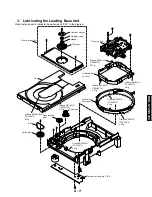
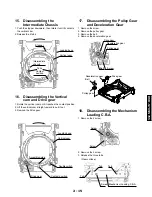
17.
Disassembling the Pulley Gear
and Deceleration Gear
1. Remove the screw.
2. Remove the pulley gear.
3. Remove the belt.
4. Remove the deceleration gear.
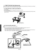
16.
Disassembling the Vertical
cam and Drive gear
1. Rotate the vertical cam until it reaches the contact position.
2. Lift the vertical cam straight upward to pull it out.
2. Remove the Drive gear.
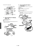
15.
Disassembling the
Intermediate Chassis
1. Push the stopper downward, then rotate it until it contacts
the vertical cam.
2. Release the 2 tabs.
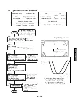
18.
Disassembling the Mechanism
Loading C.B.A.
1. Remove the 2 screw.
2. Remove the 2 screw.
3. Release the three tabs.
Loading base
Vertical cam
Contact
position
Intermediate
chassis
Tabs
Stopper
Loading base
Vertical cam
Double switch
Drive gear
Contact position
Assembly guide
Pulley gear
Deceleration gear
Drive gear
Belt
Screw
Drive gear
Deceleration gear
Belt
Pulley gear
Mechanism Loading C.B.A.
Screw
Tab
(Rear surface)
Tab
Tab
Screw
Screw
Содержание DVD-S705
Страница 7: ...DVD S795 S705 1 5 REAR PANELS U C models DVD S795 S705 B G models G model Gold A model ...
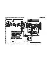
Страница 39: ...3 3 3 4 BLOCK DIAGRAM 1 OVERALL BLOCK DIAGRAM ...
Страница 40: ...3 5 2 SERVO BLOCK DIAGRAM 3 6 ...
Страница 41: ...3 7 3 VIDEO BLOCK DIAGRAM 3 8 ...
Страница 42: ...3 9 4 AUDIO BLOCK DIAGRAM 3 10 ...
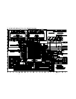
Страница 58: ...0 0 0 0 9 0 0 9 0 4 9 2 7 2 6 2 7 2 6 3 41 16 VIDEO COMP SCHEMATIC DIAGRAM FOR U C MODELS U C MODELS 3 42 ...
Страница 60: ...9 0 0 0 0 0 8 9 0 0 3 45 18 FRONT SW HEAD PHONE POWER SW SCHEMATIC DIAGRAM 3 46 ...