


DVD-S795/S705
2 - 12
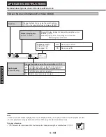
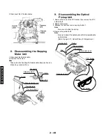
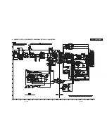
3. Insert the pickup FPC into connector FP5201 on the module
C.B.A.
13.
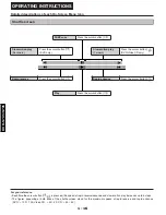
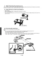
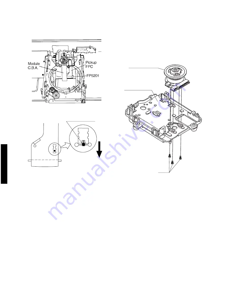
Disassembling the Spring
Motor Unit
1. Remove the three screw.
Note
Be sure to adjust the optical pickup tilt after replacing
the spindle motor unit.
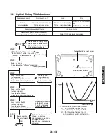
4. Remove the solder from the pickup FPC’s soldered short-circuit
5. Adjust the optical pickup tilt after removing the solder.
(Refer to page 2-13, Optical Pickup Tilt Adjustment.)
Remove the solder.
Solder removal
direction
(Magnified view)
Open the circuit after short-circuiting it.
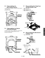
Screw
Traverse chassis
Spindle motor unit
Содержание DVD-S705
Страница 7: ...DVD S795 S705 1 5 REAR PANELS U C models DVD S795 S705 B G models G model Gold A model ...
Страница 39: ...3 3 3 4 BLOCK DIAGRAM 1 OVERALL BLOCK DIAGRAM ...
Страница 40: ...3 5 2 SERVO BLOCK DIAGRAM 3 6 ...
Страница 41: ...3 7 3 VIDEO BLOCK DIAGRAM 3 8 ...
Страница 42: ...3 9 4 AUDIO BLOCK DIAGRAM 3 10 ...
Страница 58: ...0 0 0 0 9 0 0 9 0 4 9 2 7 2 6 2 7 2 6 3 41 16 VIDEO COMP SCHEMATIC DIAGRAM FOR U C MODELS U C MODELS 3 42 ...
Страница 60: ...9 0 0 0 0 0 8 9 0 0 3 45 18 FRONT SW HEAD PHONE POWER SW SCHEMATIC DIAGRAM 3 46 ...