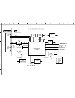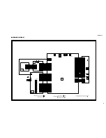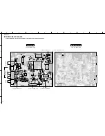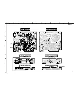
DVD-S559
13
DVD-S559
Symptoms
The power is not turned on.
An opening screen is not
displayed on the monitor.
(The FL display (V651) lights.
The mechanism does not work.)
A tray cannot be opened.
(An opening screen is
displayed on the monitor)
■
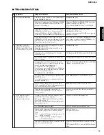
TROUBLESHOOTING
Diagnosis Contents
“Check the voltage of AT+3.3V, -28V and FL-DC+/-
on the POWER P.C.B. Ass’y.”
Are wires of output connector CP502 on the POWER
P.C.B. Ass’y and CP4003 on the DVD P.C.B. Ass’y
disconnected or damaged ?
Check that the voltage at IC651-pin 10 (K 1) on the
OPERATION 1 P.C.B. Ass’y “becomes about 2.7V
when the POWER key (SW667, OPERATION 2
P.C.B. Ass’y)” is pressed and 0 V when it is released.
Check that the voltage at OS651-pin 1 (IR) on the
OPERATION 1 P.C.B. Ass’y is in the range between 0
and 3.3 V while receiving signals from the Remote
Control when any key on it is pressed.
Check the voltage of E+6.8V and SW+3.3V on the
POWER SUPPLY Unit.
Check the voltage of P.ON-H is about 2.8V on the
POWER SUPPLY Unit.
Check the voltage of IC4006-pin 2 is 1.8V on the
DVD P.C.B. Ass’y.
Is a resonator (X4001 : 27MHz) on the DVD P.C.B.
Ass’y oscillating ?
Is a signal input into IC4004-pin26 (PCE#) on the
DVD P.C.B. Ass’y ? (Is a signal “H” for 80 mS and
then “L” after the power is turned on ?)
➞
Communication with flash ROM.
Are the signals input into IC4005-pin 16 (DWE#), pin
19 (DCS#) and pin 38 (SDCLK) on the DVD P.C.B.
Ass’y ? (Is a signal fluctuating ?)
➞
Communication with SDRAM
Is a signal output from IC4004-pin 28 (PRD#) on the
DVD P.C.B. Ass’y ?
(Is a signal fluctuating for several hundred mS after
the power is turned on ?)
Are the signals of IC4001-pin 5 (SDA) and pin 6
(SCL) on the DVD P.C.B. Ass’y fluctuating for one or
two seconds after the power is turned ?
Check the video signal path between DVD IC
(IC4002) on the DVD P.C.B. Ass’y and Video-out
(J8001) terminal.
Does the voltage of CP2302-pin 3 and pin 1 on the
DVD P.C.B. Ass’y change normally ?
SW-1-pin 3 (OPEN) on the DVD Mechanism Unit :
Tray is fully opened: “L”
SW-2-pin 5 (CLOSE) on the DVD Mechanism Unit :
Tray is fully closed: “L”
Is a LOAD-DRV signal reaching ?
Are the signals output from IC101-pin 36 and pin 37
(CN103-pin 1 and pin 2) on the DVD Mechanism
Unit ?
Pin 4:
Approx. 45V during opening tray approx. 0V
during closing tray.
Pin 5:
Approx. 0V during opening tray approx.
4.5V during closing tray.
Are wires of CP2302 and CP2303 on the DVD P.C.B.
Ass’y disconnected or damaged ?
Possible Defective Points
POWER P.C.B. Ass’y
Connector CP502 on the POWER P.C.B. Ass’y and
CP4003 on the DVD P.C.B. Ass’y.
Cable (From POWER P.C.B. Ass’y to DVD P.C.B.
Ass’y).
Tact SW (SW660,662,664,665,667) on the
OPERATION 2 P.C.B. Ass’y.
(when operation of only the POWER key on the main
unit is not accepted)
Remote receiver section on the OPERATION 1 P.C.B.
Ass’y. (when operation of only the POWER key on
the Remote Control is not accepted)
POWER P.C.B. Ass’y.
1.8V Regulator IC (IC4006) on the DVD P.C.B. Ass’y.
Crystal resonator (X4001) on the DVD P.C.B. Ass’y.
DVD IC (IC4002), Flash ROM (IC4004) and SDRAM
(IC4005) on the DVD P.C.B. Ass’y.
Flash ROM (IC4004) on the DVD P.C.B. Ass’y.
EEPROM (IC4001) on the DVD P.C.B. Ass’y.
Video circuit after DVD IC (IC4002) on the DVD
P.C.B. Ass’y.
Tray SW on the DVD Mechanism Unit.
DVD IC (IC4002) on the DVD P.C.B. Ass’y.
DVD P.C.B. Ass’ y
FTS Driver IC (IC2301)
Connector CP2302 and CP2303 on the DVD P.C.B.
Ass’y.
Cable (From DVD P.C.B. Ass’y to DVD Mechanism
Unit).
No.
1
2
3
Содержание DVD-S559
Страница 5: ...DVD S559 5 DVD S559 FRONT PANEL REAR PANEL WG11920 DVD REMOTE CONTROL ...
Страница 34: ...DVD S559 ...

