

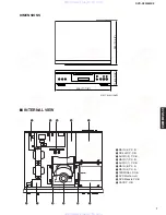


DVD-S2300MK2
9
DVD-S2300MK2
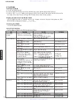
SL5002
SL5001
Solder
Terminal P.C.B.
Flexible Cable
Tray Lid
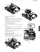
Fig. 4
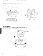
5
5
DVD-Mechanism
CB1
CB6
3 x 10 -8
3 x 10 -8
Fig. 5
Fig. 6
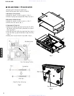
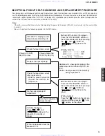
4. Removal of DVD-mechanism
CAUTION
• When removing the DVD-Mechanism, make sure to follow steps
a. to e. below in that order to prevent the laser diode from being
damaged.
• When installing the DVD-Mechanism, make sure to follow in the
reverse order (from e. to a.) of the following procedure.
a. Remove 4 screws (
5
). (Fig. 5)
b. Turn over the DVD-Mechanism. (Fig. 6)
c. Solder the lands (SL5001/SL5002) in the Terminal P.C.B.. (Fig.
6)
Notes
• Use an anti-static soldering iron to short-circuit and unshort-
circuit laser diode.
• After you have finished repairing the laser diode, follow the
correct procedure to remove the solder from the short-circuit
location.
d. Disconnect the connectors CB1 and CB6. (Fig. 5)
e. Remove the DVD-Mechanism.
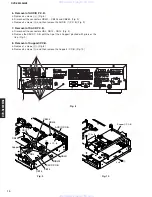
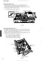
5. Removal of Front Panel Unit
7
). (Fig. 7)
c. Disconnect the connectors CB10, CB602, CB605, CB803 and
CB822 and then remove the Front Panel Unit. (Fig. 7)
6
8
6
CB602
CB803
CB822
3 x 8
Bonding
CB10
CB605
3 x 8
3 x 8
Fig. 7
www. xiaoyu163. com
QQ 376315150
9
9
2
8
9
4
2
9
8
TEL 13942296513
9
9
2
8
9
4
2
9
8
0
5
1
5
1
3
6
7
3
Q
Q
TEL 13942296513 QQ 376315150 892498299
TEL 13942296513 QQ 376315150 892498299