


DVD-S2300MK2
16
DVD-S2300MK2
FL Display
SODC DRAM OK or NG
DSD DRAM OK or NG
EEPROM OK or NG
TEST TONE
DrvMute Off
ShiftReg 55h
ShiftReg AAh
Video Mode 1 or 2 or 3
DVD Laser ON
CD Laser ON
Example: Ver L008
Example: SUB M004
Adj1 OK or ERR
Adj2 OK or ERR
Adj3 OK or ERR
Adj4 OK or ERR
Adj5 OK or ERR
Adj6 OK or ERR
Tr On OK or ERR
Tr Off OK or ERR
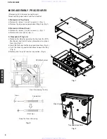
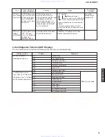
3. Test Mode
• Starting Test Mode
a. Turn on the POWER switch.
b. Press the SACD/DVD button to set to the SACD mode, and the SACD mode indicator lights up.
c. Press the " "+"
" buttons on the player and the "PLAY" button on the remote control unit to start the
test mode. At this time, the user setting of SACD mode returns to their factory settings.
• Display provided when Test Mode started
After all segments of the FL indicator light up, the firmware version of the panel microprocessor (IC40:
MN102HF60K) is displayed. Example: Ver L008
• Canceling Test Mode
Turn off the POWER switch.
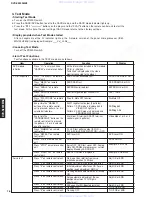
• List of Test Functions
Test functions available in the TEST mode are as follows.
Item
DVD module
initialize
P.C.B. inspection
Servo test
Operation
Press "
" on main unit and
"CANCEL" on remote controller.
Press "TOP MENU" on remote
control unit.
Press "MENU" on remote
control unit.
Press "ANGLE" on remote
control unit.
Press "AUDIO" on remote
control unit.
Press "PLAY MODE" on remote
control unit.
Every time the "MARKER"
button on the remote control
unit is pressed, pattern 1 or 2 is
selected alternately.
Every time the
"PROGRESSIVE" button on the
remote control unit is pressed,
the pattern 1, 2 or 3 is selected
one after another.
Press "DIMMER" on remote
control unit.
Press "REPEAT" on remote
control unit.
Press "A-B" on remote control
unit.
Press "STOP" on remote control
unit.
Press "VIDEO OFF" on remote
control unit.
Press "1" on remote control unit.
Press "2" on remote control unit.
Press "3" on remote control unit.
Press "4" on remote control unit.
Press "5" on remote control unit.
Press "6" on remote control unit.
Press "9" on remote control unit.
Press "0" on remote control unit.
Function
All the information included in DVD module
P.C.B. is initialized.
"Initialized" is displayed on the video
monitor connected to the player.
SODC DRAM write/read test
DSD DRAM test
EEPROM write/read test
DSD test signal output channel ON
Drive IC Mute OFF function
SHIFT register test output (2 patterns)
Pattern 1: DVD mode is displayed and
VIDEO OFF lights up.
Pattern 2: SACD mode is displayed and
PROGRESSIVE lights up.
S terminal, D terminal, SCART terminal
control signal (3 patterns)
FL, LED test pattern output (All ON
→
FL:12--9AB, LED:DVD/VOFF ON/
→
OFF)
DVD laser ON
CD laser ON
Servo OFF, OSD test signal OFF, Analog
Mute ON, PANEL microprocessor version
display. Standby LED ON/OFF
Sub-CPU version is displayed.
Start-up of disc rotation from servo
initialize operation (1000rpm)
Focus ON from disc detection operation
Initial adjustment after focus ON: Focus
position rough adjustment DM CLV
Tracking balance adjustment and tracking
ON
Servo automatic adjustment (Focus
position adjustment, FO/TR gain
adjustment)
FEP equalizer EQ/Boost adjustment
Tracking ON
Tracking OFF
www. xiaoyu163. com
QQ 376315150
9
9
2
8
9
4
2
9
8
TEL 13942296513
9
9
2
8
9
4
2
9
8
0
5
1
5
1
3
6
7
3
Q
Q
TEL 13942296513 QQ 376315150 892498299
TEL 13942296513 QQ 376315150 892498299