


YSP-3000/YSP-30D/HTY-7030
18
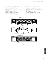
• RS232C conversion jig.
For the details, refer to page 107.
●
Preparation and precautions before starting
the operation
• Download firmware dounloader program and firm-
ware from the specified source to the same folder of
the PC.
• Prepare the above specified RS232C cross cable.
• While writing, keep the other application software on
the PC closed.
It is also recommended to keep the software on the
task tray closed as well.
■
UPDATING FIRMWARE /
ファームウェアの書き込み
下記の部品をサービス部品に交換した場合、下記の手順
により最新のファームウェアの書き込みを行ってくださ
い。
DSP P.C.B.
INPUT P.C.B.のマイコン(IC16)
DSP P.C.B.のDSP1(TI1 Flash ROM、IC12)
DSP P.C.B.のDSP2(TI2 Flash ROM、IC18)
● 必要なツール
・ プログラム書き込み用プログラム
マイコン用 .......................................... FlashSta.exe
DSP1(TI1 Flash ROM)用
.......................... DSP FLASHER (YSP̲TI1).exe
DSP2(TI2 Flash ROM)用
............................ spDownloader̲2̲0̲x̲xxx.exe
・ ファームウェア
マイコン用
...................................................... Y3000̲vx.mot
......................................................... Y3000̲vx.id
DSP1(TI1 Flash ROM)用
............................... Ysp3k4k̲data1̲Verx̲xr.hex
DSP2(TI2 Flash ROM)用
.............................................. Y3KMPxxxxxxA.bin
・ RS232Cクロスケーブル D-sub 9pinメス
(仕様)
After replacing the following parts with the replacement
parts, update the latest firmware according to the following
procedure.
DSP P.C.B.
Microprocessor (IC16) of INPUT P.C.B.
DSP1 (TI1 Flash ROM, IC12) of DSP P.C.B.
DSP2 (TI2 Flash ROM, IC18) of DSP P.C.B.
●
Required tools
• Program downloader programs
For microprocessor .............................. FlashSta.exe
For DSP1 (TI1 Flash ROM)
........................... DSP FLASHER (YSP_TI1).exe
For DSP2 (TI2 Flash ROM)
............................ spDownloader_2_0_x_xxx.exe
• Firmware
For microprocessor
...................................................... Y3000_vx.mot
......................................................... Y3000_vx.id
For DSP1 (TI1 Flash ROM)
............................... Ysp3k4k_data1_Verx_xr.hex
For DSP2 (TI2 Flash ROM)
.............................................. Y3KMPxxxxxxA.bin
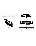
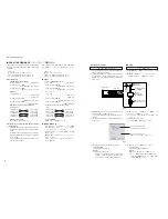
• RS232C cross cable “D-sub 9 pin female”
(Specifications)
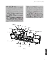
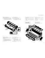
Bottom view
⇑
Top side
Writing port /
書き込み用ポート
RS232C
conversion jig /
RS232C変換冶具
RS232C cross cable /
RS232クロスケーブル
Reset
switch /
リセット
スイッチ
Flexible flat cable 9P /
カード電線9P
Fig. 1
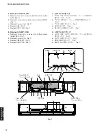
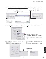
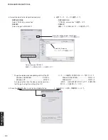
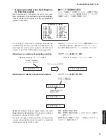
5. 送信データ、ポートを選択します。(Fig. 2)
・ Select Program
Internal flash memoryを選択します。
・ RS232C
接続しているRS-232Cポートを選択します。
5. Select the data to be transmitted and port. (Fig. 2)
·
Select Program
Select Internal flash memory
·
RS232C
Select the port of RS-232C
*
For selection of the port, COM1 to 4 can be used.
As COM5 or higher port cannot be used, select
out of COM 1 to 4 of the setting on the PC side.
※ ポートの選択はCOM1〜4までが使用できます。
COM5以上は使用できませんので、PC側の設定で
COM1〜4を選択してください。
Fig. 2
Select Internal flash memory
Internal flash memoryを選択します
Select the port of RS-232C
接続しているRS-232Cポートを選択します
Pin No.2 RxD
Pin No.2 RxD
Pin No.3 TxD
Pin No.3 TxD
Pin No.5 GND
Pin No.5 GND
Pin No.7 RTS
Pin No.7 RTS
Pin No.8 CTS
Pin No.8 CTS
・ RS232C 変換冶具
詳細は107ページを参照してください。
● 操作前の準備と注意
・ PCへ指定のダウンロード先からファームウェア書き
込み用プログラムおよび、ファームウェアを同じ
フォルダにダウンロードしてください。
・ RS232Cクロスケーブルは必ず上記仕様のものを用
意してください。
・ 書き込み時は、PC上の他のアプリケーションソフト
は閉じてください。
さらに、タスクトレイ上にあるソフトも閉じておく
ことを推奨します。
Pin No.2 RxD
Pin No.2 RxD
Pin No.3 TxD
Pin No.3 TxD
Pin No.5 GND
Pin No.5 GND
Pin No.7 RTS
Pin No.7 RTS
Pin No.8 CTS
Pin No.8 CTS
マイコンへの書き込み
1. 本機の電源を切り、電源コードをACコンセントから抜
きます。
2. 本 機 の 書 き 込 み 用 ポ ー ト と P C の シ リ ア ル ポ ー ト
(RS232C)を下記のように接続します。(Fig. 1)
● 操作方法
Writing to the microprocessor
1. Turn off the power of main unit and disconnect the
power cable from the AC outlet.
2. Connect the writing port of the main unit to the serial
port (RS232C) of the PC with RS232C cross cable,
RS232C conversion jig and flexible flat cable as shown
below. (Fig. 1)
●
Operation Procedure
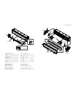
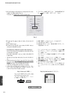
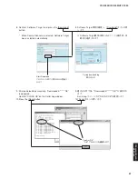
3. 本機のリセットスイッチを押しながら、電源コードを
ACコンセントに接続します。(Fig. 1)
※ リセットスイッチは、先の細いピンなどで押してく
ださい。
4. FlashSta.exeを立ち上げます。
すると下記の画面が表示されます。(Fig. 2)
3. While pressing the reset switch of main unit, connect
the power cable to the AC outlet. (Fig. 1)
* Use a fine tipped pin or the like to push the reset
switch.
4. Start up FlashSta.exe, the screen will appear as shown
below. (Fig. 2)
Содержание Digital Sound Projector YSP-3000
Страница 78: ...78 YSP 3000 YSP 30D HTY 7030 YSP 3000 YSP 30D HTY 7030 MEMO MEMO ...
Страница 111: ...111 YSP 3000 YSP 30D HTY 7030 YSP 3000 YSP 30D HTY 7030 ...
Страница 112: ...112 YSP 3000 YSP 30D HTY 7030 YSP 3000 YSP 30D HTY 7030 ...
Страница 113: ...113 YSP 3000 YSP 30D HTY 7030 YSP 3000 YSP 30D HTY 7030 ...
Страница 114: ...114 YSP 3000 YSP 30D HTY 7030 YSP 3000 YSP 30D HTY 7030 ...
Страница 115: ...YSP 3000 YSP 30D HTY 7030 115 ...
Страница 116: ...YSP 3000 YSP 30D HTY 7030 ...