background image

Using Peak Hold

41

D24—Owner’s Manual

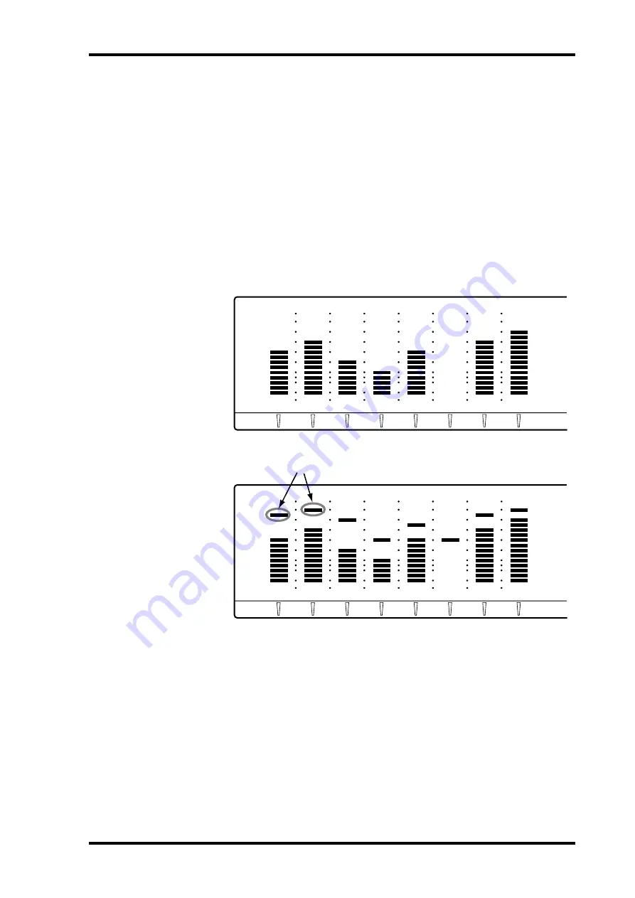
Using Peak Hold

By keeping the highest lit segment of each meter illuminated, the Peak Hold function 
provides a convenient way to check for signal peaks.

Peak Hold can be set so that the highest lit segment of each meter remains lit for 800 ms 
(MOMENTARY) or continuosuly (PERMANENT). See “Setting the Peak Hold Mode” 
on page 170 for more information.

1

Press the [PEAK HOLD] button to turn on the Peak Hold function.

The PEAK HOLD indicator lights up.

2

Press the [PEAK HOLD] button again to turn off the Peak Hold function.

The PEAK HOLD indicator goes out.

To reset the Peak Hold function, turn it off and then on again.

OVER

READY

0

2

6

12

20

30

42

60

–dB

OVER

READY

0

2

6

12

20

30

42

60

–dB

R

L

Peak Hold: Off

Peak Hold: On

OVER

READY

0

2

6

12

20

30

42

60

–dB

OVER

READY

0

2

6

12

20

30

42

60

–dB

R

L

Peak levels

Содержание D24

Страница 1: ...0 1 4 7 8 R 7 6 5 4 3 2 1 RECORD READY SOLO SELECT MONITOR SELECT PEAK HOLD AUTO INPUT ALL INPUT FORMAT CHASE L 2 5 8 3 6 9 UNDO REDO EDIT JOG ON JOG DATA SHUTTLE CURSOR PROJECT SEARCH RTN TO ZERO REW FF STOP PLAY REC ROLL BACK LAST REC SET DIGITAL MULTITRACK RECORDER REPEAT REHE PHONES LEVEL 0 10 ON POWER OFF PHONES B A B A AUTO PUNCH IN OUT INT 24 48K MASTER WC BIT FS TC M S F READY 0 2 6 12 20 ...

Страница 2: ... 030 2828425 Do not throw away the battery Instead hand it in as small chemical waste FCC INFORMATION U S A 1 IMPORTANT NOTICE DO NOT MODIFY THIS UNIT This product when installed as indicated in the instructions contained in this manual meets FCC requirements Modifications not expressly approved by Yamaha may void your authority granted by the FCC to use the product 2 IMPORTANT When connecting thi...

Страница 3: ...RSEL Usynlig laserstråling ved åbning Undgå udsaettelse for stråling VAROITUS Laitteen käyttäminen muulla kuin tässä käyttöohjeesa mainitulla tavalla saattaa altistaa käyttäjän turvallisuusluokan 1 ylittävälle näkymättömälle lasersäteilylle VARNING Om apparaten används på annat sätt än i denna bruksanvisning specificerats kan användaren utsättas för osynlig laserstrålning som överskrider gränsen f...

Страница 4: ...ool Blocking the ventilation slots or obstructing the fan s airflow is a potential fire hazard Do not attempt to modify the D24 This is a potential fire and electrical shock hazard The D24 operating temperature is between 5 C and 35 C 41 F and 95 F Cautions Allow enough free space around the unit for normal ventilation This should be 10 cm behind and 20 cm above These distances should also be adop...

Страница 5: ...ckage Contents The D24 package should contain the following items Contact your Yamaha dealer if you are missing an item D24 Digital Multitrack Recorder This manual Power cord MO disk Disk eject tool Trademarks ADAT MultiChannel Optical Digital Interface is a trademark and ADAT and Alesis are registered trademarks of Alesis Corporation Apple and Macintosh are registered trade marks of Apple Compute...

Страница 6: ... 23 Connecting the Power Cord 24 Turning On Off the D24 24 Write Protecting Disks 24 Inserting Ejecting Disks 25 Formatting MO Disks 26 Transport Operation Table 27 Indicator Status Tables 28 4 Recording 29 About Projects 30 Preparing to Record 31 Setting the Recording Resolution 32 Recording 33 Conserving Disk Space 35 Undoing a Recording or Edit 35 Rehearsing 36 Extending the Top of a Project 37...

Страница 7: ...oring Locate Points 64 Storing Locate Points Automatically 65 Recalling Locate Points 66 7 Punch In Out Recording 67 About Punch In Out Recording 68 Manual Punch In Out Rehearsal 69 Manual Punch In Out Recording 70 Setting the LAST REC IN OUT Points 71 Auto Punch In Out Rehearsal 72 Auto Punch In Out Recording 73 Setting the Pre roll Time 76 Setting the Post roll Time 76 8 Editing Projects 77 Copy...

Страница 8: ...d 139 Transmitting MTC 139 Timecode Hookup Examples 140 13 Multiple D24s Video Sync 143 Multiple D24s 144 Expanding the Number of Tracks 145 Extending the Recording Time 147 Setting the Serial Point 149 Using Video Sync 149 Terminating BNC Video Sync Distribution 150 Connecting a Video Editor 151 Video Hookup Example 151 14 SCSI External Disk Drives 153 SCSI the D24 154 Using External Disk Drives ...

Страница 9: ...ts 178 Using MMC MIDI Machine Control 178 17 Digital Audio I O 181 About mini YGDAI Cards 182 Card Specifications 183 Choosing Digital I O Cards 183 Choosing D24 Slots 184 Selecting Slot Inputs 184 Installing Cards 185 Using Dual AES EBU Mode 186 Using the Coaxial Digital Input Output 187 Assigning the Coaxial Input Output 188 Emphasis the D24 188 SCMS the D24 188 Digital I O Wordlength 189 Troubl...

Страница 10: ...Welcome to the D24 1 D24 Owner s Manual Welcome to the D24 1 In this chapter Welcome to the D24 2 About this Manual 3 Installing the D24 3 D24 Features 4 Choosing MO Disks 6 ...

Страница 11: ...r individual track monitoring Other fea tures include 6 varispeed A B repeat playback and fast forward or rewind at 8x or 16x normal playback speed In addition to the 99 locate memories the A B Last Rec In and Last Rec Out points offer additional ways locate specific positions quickly repeatedly and accurately Other quick locate functions include Project Search Return to Zero and Roll Back Locatio...

Страница 12: ...eatures About this Manual This Owner s Manual contains all the information you need in order to operate your D24 Digital Multitrack Recorder Use the table of contents to familiarize yourself with the organization of this manual and locate topics and use the index to locate specific information A glossary of D24 related jargon is provided on page 201 The following format is used throughout this Own...

Страница 13: ...40 MB MO disks 16 bit 44 1 kHz 8 virtual tracks per main track for a total of 64 tracks Autopunchin outrecordingwithmultipletakecapability recordandchoosethebest from up to 99 takes Manual and auto punch in out recording with rehearsal Playback Video machine like shuttle playback Position nudge with audio listen Solo function for individual track monitoring 6 varispeed A B repeat playback Quick Lo...

Страница 14: ...racy 50 to 200 time compression and expansion for audio fit video applications Pitch Change function provides pitch change without speed change Easy Operation Tape recorder like transport controls Large vacuum fluorescent display with large easy to read counter 16 segment track level meters with selectable normal and fine scales Projects can be titled for easy identification Synchronization SMPTE ...

Страница 15: ...ampling rate For performance reasons it s recommended that you do not use 128 MB MO disks When tracks that have already been recorded are playing back depending on the num ber and performance of those tracks i e how heavily they ve been edited the number of tracks available for simultaneous recording is reduced Use the Optimize function to arrange the recorded sound files for optimum performance S...

Страница 16: ...for a given recording resolution sampling rate and disk capacity as follows First multiple the recording resolution by the sampling rate to get the number of bits produced per second e g 16 44100 705 600 bits per second Then divide that by eight to get the number of bytes per sec ond e g 705 600 8 88 200 bytes per second Multiply that by 60 to get the number of bytes required per minute e g 88 200...

Страница 17: ...Touring the D24 2 In this chapter Front Panel 10 Display 10 Transport Controls 12 Power Switch Phones 14 Jog Data Shuttle Cursor Controls 15 Function Buttons 16 Peak Monitor Format Chase Buttons 17 Keypad 18 Track Buttons 19 Rear Panel 20 ...

Страница 18: ... Zero on page 49 for more information 00 00 00 00 Y A M A H A D 2 4 OVER READY 0 2 6 10 12 14 20 18 30 20 42 26 60 dB OVER ABS H LOCK TIME DISPLAY CAPTURE ABS REL REMAIN VARI SPEED UTILITY SETUP PROJECT SELECT LOC MEM RECALL LOC MEM STORE LOCATE ENTER CANCEL 0 1 4 7 8 R 7 6 5 4 3 2 1 RECORD READY SOLO SELECT MONITOR SELECT PEAK HOLD AUTO INPUT ALL INPUT FORMAT CHASE L 2 5 8 3 6 9 UNDO REDO EDIT JO...

Страница 19: ...or shows whether or not the D24 is locked to the selected wordclock source See Selecting a Wordclock Source on page 124 for more information G CHASE indicator This indicator shows whether or not the D24 is synchronized to the external timecode source It flashes when the D24 is chasing and lights up continuously when it s fully synchronized See Chasing External Timecode on page 138 for more informa...

Страница 20: ...tion C RTN TO ZERO button This button is used to locate the zero position See Returning to Zero on page 60 for more information D LAST REC IN OUT buttons indicators These buttons are used to set and locate the LAST REC IN and LAST REC OUT points The IN and OUT indicators light up when the respective IN or OUT point is set See Setting the LAST REC IN OUT Points on page 71 and Locating the LAST REC ...

Страница 21: ...t the Key pad Timecode Input mode See Storing Locate Points Automatically on page 65 and Locating Positions Directly on page 63 respectively for more information K REHE button indicator This button is used to engage Rehearsal Standby mode and when pressed together with the PLAY button punch in rehearsal In Rehearsal mode recording can be practiced with automatic playback and input monitor switchin...

Страница 22: ... the PLAY button to start recording The REC button indicator lights up while recording See Recording on page 29 for more infor mation Power Switch Phones A POWER switch This switch is used to turn on and off the D24 It s recessed to prevent accidental oper ation See Turning On Off the D24 on page 24 for more information B PHONES LEVEL control This control is used to adjust the volume level of the ...

Страница 23: ... dial When JOG ON is on the JOG DATA dial is used to nudge the current position while auditioning a small section of recorded material See Nudging the Current Position on page 53 for more information When the VARI SPEED UTILITY SETUP V TRACK SELECT or EDIT but ton is pressed the JOG DATA dial is used to select functions and set parameter values C SHUTTLE CURSOR ring This is a dual function control...

Страница 24: ...yback See Using Varispeed on page 55 for more information E ABS REL button This button is used to set the counter mode to either Absolute ABS the default set ting or Relative REL See UsingAbsolute Relative Zero on page 49 for more infor mation F CAPTURE button This button is used to capture time positions while the D24 is stopped or during rewind fast forward playback recording or rehearsal Captur...

Страница 25: ...t point See Monitoring on page 42 for more information C ALL INPUT button indicator This button selects the All Input function When the All Input function is on all track inputs are monitored regardless of the transport mode RECORD READY buttons The ALL INPUT indicator lights up when the All Input function is on See Monitor ing on page 42 for more information D FORMAT button indicator This button ...

Страница 26: ...when the Locate Memory Recall function is on See Recalling Locate Points on page 66 for more information D LOC MEM STORE button indicator This button is used to store locate memories The LOC MEM STORE indicator lights up when the Locate Memory Store function is on See Storing Locate Points on page 64 for more information E LOCATE button This button is used to locate the position specified on the 2...

Страница 27: ...dicator flashes During recording or rehearsal the corresponding indicator lights up continuously See Recording on page 33 for more information B SOLO SELECT buttons indicators 1 8 These buttons are used to solo individual tracks When a track is soloed the corre sponding SOLO SELECT indicator lights up See Soloing Tracks on page 48 for more information 8 7 6 5 4 3 2 1 RECORD READY SOLO SELECT 1 2 ...

Страница 28: ...C Wordclock Distribution on page 131 for more information E WORD CLOCK OUTPUT connector This BNC connector transmits the wordclock signal received at the WORD CLOCK INPUT when the WORD CLOCK 75Ω TERM THRU switch is set to THRU or the internally generated wordclock signal when this switch is set to TERM See Wordclock Connections on page 123 for more information F WORD CLOCK INPUT connector This BNC...

Страница 29: ... Number of Tracks on page 145 for more information L Cooling fan The cooling fan keeps the internal components cool See Installing the D24 on page 3 for more information M AC IN connector This connector is used to connect the D24 to an AC outlet using the supplied power cord See Connecting the Power Cord on page 24 for more information N TIMECODE OUTPUT connector This male XLR 3 32 connector balan...

Страница 30: ...s Manual The Basics 3 In this chapter Connecting the Power Cord 24 Turning On Off the D24 24 Write Protecting Disks 24 Inserting Ejecting Disks 25 Formatting MO Disks 26 Transport Operation Table 27 Indicator Status Tables 28 ...

Страница 31: ...ot intend to use should be disconnected before turning on the D24 See Using Exter nal Disk Drives on page 154 for more information 1 Press the POWER switch to turn on the D24 Afterseveralseconds NODISK appearsonthedisplayandtheD24 is ready for use 2 Press the POWER switch again to turn off the D24 Write Protecting Disks MO disks feature write protect tabs similar to those found on floppy disks all...

Страница 32: ...ing in the D24 the number and title of the first project appear on the display If the disk has been formatted for use with the D24 but not yet used for recording 01 NO TITLE is displayed 2 To eject a disk press the eject button as shown below The eject button also functions as a drive activity indicator lighting up when the disk drive is busy The eject button does not operate during recording and ...

Страница 33: ...rive If the disk is new or has been formatted for use in a device other than the D24 the mes sage UNFORMATTED appears on the display 2 Press the FORMAT button The FORMAT indicator flashes and FORMAT DISK ARE YOU SURE flashes on the display 3 Press the ENTER button PRESS REC PLAY appears on the display 4 Press the REC and PLAY buttons simultaneously to format the disk or the CANCEL button to cancel...

Страница 34: ... rehearsal rew Cancel rew Cancel rew1 1 Release button for normal playback FF FF 8x FF 8x while pressing Stop rew FF FF 16x Stop rec FF FF Stop rehearsal FF Cancel FF Cancel FF1 STOP X Stop play Stop rew Stop FF Punch out stop Cancel stop Punch out stop Cancel stop Stop play PLAY Play X Stop rew play Stop FF play Punch out play Rehearsal punch in Punch out play Cancel play X REC X REC PLAY to star...

Страница 35: ... FF 16x STOP PLAY REC REHE z READY REC READY OFF READY REC READY ON z z z z z z Eject1 1 Indicates drive activity Lights up continuously when a disk is being loaded or ejected z z z z z Indicator Status Condition LAST REC IN LAST REC IN point has not been set LAST REC IN point has been set LAST REC OUT LAST REC OUT point has not been set LAST REC OUT point has been set A A point has not been set A...

Страница 36: ...reparing to Record 31 Setting the Recording Resolution 32 Recording 33 Conserving Disk Space 35 Undoing a Recording or Edit 35 Rehearsing 36 Extending the Top of a Project 37 Checking the Time Remaining 38 Metering 39 Using Normal Fine Metering 40 Using Peak Hold 41 Monitoring 42 ...

Страница 37: ...different to the current setting the project s sampling rate flashes in the FS window and you must use the Wordclock function Selecting a Wordclock Source on page 124 to set the sampling rate of the D24 to match that of the project otherwise playback will be distorted Highlighted settings are stored with each project WC INT TC MASTER BIT 16 FS 44 1 kHz Frame rate 30 Start 00 00 00 00 Title POP SON...

Страница 38: ...ect on disk is 06 for example the next new project will be 07 Projects can be titled for easy identification See Titling Projects on page 81 for more informa tion D24 disks contain sound files and project settings files Preparing to Record This section explains how to prepare for recording 1 Select a wordclock source See Selecting a Wordclock Source on page 124 for more information Although the wo...

Страница 39: ...ing resolution you choose will ultimately depend on your application and recording system There s no point selecting a 20 or 24 bit recording resolution on the D24 if your digital mixing console s A D converters are only 16 bit If you intend to deliver your project to a third party another studio for example consult them and agree on a recording resolution before you start recording on the D24 In ...

Страница 40: ...sor Press the CANCEL button to return to the previous value 3 Press the ENTER button The absolute start time appears on the main counter 4 Use the RECORD READY buttons to select tracks for recording The corresponding READY indicators flash 5 Set the recording levels in conjunction with the D24 track meters See Metering on page 39 for more information Recording levels are typically set using the gr...

Страница 41: ...he READY indicators flash The LAST REC OUT point is set automatically and its indicator lights up To audition what you ve just recorded press the LAST REC IN button to locate the point at which recording started and then press the PLAY button to start playback Recording can be undone using the Undo Function See Undoing a Recording or Edit on page 35 for more information Projects can be titled usin...

Страница 42: ...by first deleting the silent sections using the Part Erase function see Erasing Parts on page 104 and then optimizing the disk using the Optimize function which deletes unused sound files from disk thereby freeing up space for additional recording see Recovering Disk Space on page 172 Undoing a Recording or Edit The Undo function can be used to undo the last recording or edit After recording or pe...

Страница 43: ...e See Monitoring on page 42 for more information 5 Press the REHE button The REHE button indicator flashes indicating Rehearse Standby mode To cancel Rehearse Standby mode press the STOP button 6 Press the PLAY button to start rehearsal Rehearsal starts and the PLAY button indicator and READY indicators light up contin uously The LAST REC IN point is set automatically and its indicator lights up R...

Страница 44: ...ou must use the Track Slip function to slip forward the tracks already recorded and then record the new material See Slipping Tracks on page 93 for more information In the following example a project s absolute start time is 00 00 00 00 Using the Track Slip function the four recorded tracks are slipped forward eight seconds so that new material can be recorded at the top of the project Before trac...

Страница 45: ...REMAIN button In the following example tracks 1 through 4 are selectedforrecordingandtheRemainfunctiondisplaystherecordingtimeavailablefor four tracks When tracks or parts are erased or deleted although they can no longer be accessed the actual audio data remains on disk as unused sound files taking up disk space and reducing the time available for additional recording After repeated recording and...

Страница 46: ...ral consecutive samples exceed the digital satura tion point When setting recording levels it s okay for signals to light the 0 dB indicator If the OVER indicator lights up however you should back off the input level as shown below When the Shuttle Nudge Time Compression or Pitch Change function is used track meters 7 and 8 function as stereo meters and meters 1 through 6 are turned off OVER READY...

Страница 47: ...nction 1 Press the UTILITY button The UTILITY indicator lights up 2 Use the JOG DATA dial to select LEVEL METER and then press the ENTER button The currently selected meter mode appears on the display 3 Use the JOG DATA dial to select either NORMAL or FINE 4 Press the ENTER button to activate your selection or the CANCEL button to cancel the Level Meter function 5 Press the UTILITY button again to...

Страница 48: ...NT See Setting the Peak Hold Mode on page 170 for more information 1 Press the PEAK HOLD button to turn on the Peak Hold function The PEAK HOLD indicator lights up 2 Press the PEAK HOLD button again to turn off the Peak Hold function The PEAK HOLD indicator goes out To reset the Peak Hold function turn it off and then on again OVER READY 0 2 6 12 20 30 42 60 dB OVER READY 0 2 6 12 20 30 42 60 dB R...

Страница 49: ...Tracks not selected for recording don t output anything during stop fast for ward or rewind but output playback signals during playback recording or rehearsal Tracks selected for recording output the track input signal regardless of the transport mode In the following illustration the AUTO INPUT button is turned on the default set ting Tracks not selected for recording function as before Tracks se...

Страница 50: ... and the track outputs output the track input signals regardless of the transport mode and RECORD READY button All Input is useful when you want to monitor track inputs regardless of any other settings LAST REC IN point Recording Rehearsal Playback Stop FF Rew LAST REC OUT point MONITOR SELECT AUTO INPUT ALL INPUT READY 1 Playback READY 1 ...

Страница 51: ... Using Fast Forward Rewind 46 A B Repeat Playback 47 Soloing Tracks 48 Selecting the Solo Outputs 48 Using Absolute Relative Zero 49 Using Roll back 50 Setting the Roll back Time 50 Using Virtual Tracks 51 Shuttling 52 Nudging the Current Position 53 Setting the Nudge Time 54 Using Varispeed 55 ...

Страница 52: ...nd at either 8x or 16x normal play speed 1 Press the FF button to fast forward or the REW button to rewind The respective button flashes and fast forward or rewind runs at 8x normal play speed 2 Press the FF or REW button again for fast forward or rewind at 16x normal play speed The respective button lights up continuously and fast forward or rewind runs at 16x normal play speed 3 Press the STOP b...

Страница 53: ...n the 2nd line of the display See Using the A B Points on page 61 for more information about setting the A and B points 2 Press the REPEAT button The REPEAT indicator lights up 3 Press the PLAY button to start repeat playback Playback cycles between the A and B points Repeat playback can also be started by pressing the REPEAT button during playback If the REPEAT button is pressed during repeat pla...

Страница 54: ... then press the ENTER button The current Solo Out setting appears on the display 3 Use the JOG DATA dial to select either ALL OUTPUTS or PHONES The default setting is PHONES 4 Press the ENTER button to activate your selection or the CANCEL button to cancel the Solo Out function 5 Press the UTILITY button again to leave utility The UTILITY indicator goes out When Solo Out is set to PHONES the Solo ...

Страница 55: ...point at where the SET button and RTN TO ZERO buttons are pressed In the following example the relative zero position has been set at the absolute position of 00 02 00 00 2 To select Relative counter mode press the ABS REL button The ABS indicator goes out and the REL indicator lights up 3 To select Absolute counter mode press the ABS REL button again The REL indicator goes out and the ABS indicat...

Страница 56: ...e Roll back Time The roll back time is set using the Roll Back function 1 Press the UTILITY button The UTILITY indicator lights up 2 Use the JOG DATA dial to select ROLL BACK and then press the ENTER button The currently set roll back time appears on the display 3 Use the JOG DATA dial to set the roll back time from 1 to 30 seconds 4 Press the ENTER button to activate your selection or the CANCEL ...

Страница 57: ...8 The 2nd line shows the virtual tracks assigned to those main tracks Initially each main track is assigned its respective virtual track 1 2 Use the SHUTTLE CURSOR ring to select a main track The number of the virtual track assigned to the selected main track flashes on the 2nd line of the display 3 Use the JOG DATA dial to assign a virtual track to the selected main track 4 Press the ENTER button...

Страница 58: ...8 1 4 1 2 1 2 4 3 Press the JOG ON button again or any transport button to cancel the Shuttle function The JOG ON and PLAY button indicators go off and the STOP button indicator lights up The Shuttle function requires a lot of processing power so for monitoring purposes only all tracks are mixed to tracks 7 and 8 with odd numbered tracks appearing on the output and meter of track 7 and even number...

Страница 59: ...terclockwise to nudge backwards NUDGE appears on the 1st line of the display and the position including sub frame digits appears on the 2nd line The current position is nudged forwards or backwards in sub frame steps 3 Press the JOG ON button again or any transport button to cancel the Nudge function The JOG ON and PLAY button indicators go off and the STOP button indicator lights up The Nudge fun...

Страница 60: ... 2 Use the JOG DATA dial to select NUDGE TIME and then press the ENTER button The currently set nudge time appears on the display 3 Use the JOG DATA dial to set the nudge time to 20 50 or 100 ms The default setting is 100 ms 4 Press the ENTER button to activate your selection or the CANCEL button to cancel the Nudge Time function 5 Press the UTILITY button again to leave utility The UTILITY indica...

Страница 61: ...urn off the Varispeed function The Varispeed setting is stored when the Varispeed function is turned off You can toggle between varispeed and normal speed by pressing the VARI SPEED button In addition to playback speed varispeed also affects the sampling rate and wordclock frequency If the varispeed is set to 1 for example the sampling rate and wordclock frequency decrease by 1 So with the wordclo...

Страница 62: ... Projects 58 Project Search Confirmation 58 Selecting Projects Directly 59 Returning to Zero 60 Using the A B Points 61 Locating the LAST REC IN OUT Points 62 Locating Positions Directly 63 Storing Locate Points 64 Storing Locate Points Automatically 65 Recalling Locate Points 66 ...

Страница 63: ...CH buttons When set to ON the message ARE YOU SURE appears when a different project is selected by using the PROJECT SEARCH buttons and you must press the ENTER button to confirm your selection Project search confirmation is turned on or off using the P SERCH CNFM function 1 Press the UTILITY button The UTILITY indicator lights up 2 Use the JOG DATA dial to select P SERCH CNFM and then press the E...

Страница 64: ...e PROJECT SELECT indicator lights up 2 Use the keypad or JOG DATA dial to enter the number of the project The number and title of the project appear on the display 3 Press the ENTER button to locate the top of the specified project The PROJECT SELECT indicator goes out In the following example project number 4 is selected 01 PROJECT 02 PROJECT 03 PROJECT 04 PROJECT Current position PROJECT SELECT ...

Страница 65: ...sed during playback the zero position is located and then playback continues In the following example Absolute ABS mode is used so the absolute zero position is located when the RTN TO ZERO button is pressed In the following example Relative REL mode is used so the relative zero position is located when the RTN TO ZERO button is pressed If the current project doesn t have a zero position for examp...

Страница 66: ...on appears on the 2nd line of the display A and B points are set with sub frame accuracy To set the A or B point to a specific position first locate that position see Locating Positions Directly on page 63 and then store as explained above To set the A or B point to one of the 99 locate memories first recall the locate memory see Recalling Locate Points on page 66 and then store as explained above...

Страница 67: ...set the IN point or the OUT button to set the OUT point When a point is set the corresponding indicator IN or OUT lights up See Setting the LAST REC IN OUT Points on page 71 for more information about setting the LAST REC IN and OUT points 2 Press the LAST REC IN or LAST REC OUT button to locate the IN or OUT point respectively When the LAST REC IN or OUT button is pressed during playback the stor...

Страница 68: ...st the entered value You can specify the value with sub frame accuracy by switching the Keypad Timecode Input mode to hours minutes seconds frames and sub frames To do this while hold ing down the SET button press the LOCATE button Repeat this procedure to switch the Keypad Timecode Input mode back to hours minutes and seconds 2 Press the ENTER button to fix the entered value Alternatively press t...

Страница 69: ... already stored in the locate memory appear on the display If no value has been stored in the memory is displayed 3 Use the keypad or JOG DATA dial to select a locate memory from 1 to 99 To select locate memory 15 for example press 1 and then 5 To cancel your selection and select another locate memory press the CANCEL but ton and then reenter the locate memory number 4 Press the ENTER button to st...

Страница 70: ...from 1 to 99 3 While holding down the SET button press the ENTER button The current position is stored to the selected locate memory and the next locate mem ory is selected automatically 4 Repeat step 3 to store further locate points Locate points can be stored while the D24 is stopped or during rewind fast forward playback recording or rehearsal 5 Press the LOC MEM STORE button to leave the Locat...

Страница 71: ...n reenter the locate memory number 3 Press the ENTER button to fix the selected memory number The memory number nn stops flashing Alternatively press the LOCATE button to locate the selected point straightaway 4 Press the LOCATE button to locate the recalled position The specified position is located and the position appears on the main counter as shown below 5 Press the LOC MEM RECALL button to l...

Страница 72: ...In this chapter About Punch In Out Recording 68 Manual Punch In Out Rehearsal 69 Manual Punch In Out Recording 70 Setting the LAST REC IN OUT Points 71 Auto Punch In Out Rehearsal 72 Auto Punch In Out Recording 73 Setting the Pre roll Time 76 Setting the Post roll Time 76 ...

Страница 73: ...n page 71 for more information Auto Punch allows you to record up to 99 takes You can listen to the recorded takes using the Audition Take function and pick the take that you want to keep using the Fix Take function Punch In Out Fade In Out When dissimilar sounds are digitally spliced together the discontinuity and sudden levelchangesometimesproducesanaudibleclick Tosmooththetransitionwhenusing pu...

Страница 74: ...Press the PLAY button to start playback Playback starts and the PLAY button indicator lights up 3 Press the REHE button to punch in Rehearsal starts REHEARSAL appears on the display and the REHE button indicator and READY indicators light up continuously The LAST REC IN point is set automat ically and its indicator lights up 4 Press the PLAY button to punch out The D24 stops rehearsal and continue...

Страница 75: ... RECORDING appears on the display and the REC button indicator and READY indicators light up continuously The LAST REC IN point is set automat ically and its indicator lights up 4 Press the PLAY button to punch out The D24 stops recording and continues with normal playback The REC button indicator goes out and the READY indicators flash The LAST REC OUT point is set automatically and its indicator...

Страница 76: ... or the OUT button to set the OUT point The LAST REC IN and OUT points are set with sub frame accuracy The LAST REC IN and OUT points can be located using the LAST REC IN and OUT buttons respectively See Locating the LAST REC IN OUT Points on page 62 for more information To set the LAST REC IN or OUT point to an A or B point first locate the A or B point see Using the A B Points on page 61 and the...

Страница 77: ...y 4 Press the REHE and PLAY buttons simultaneously The PLAY button indicator lights up the REHE indicator flashes and REC TAKE 1 disappears from the display The Pre roll point is located and then playback starts The Pre roll time is set using the Pre Roll function Setting the Pre roll Time on page 76 5 Rehearsal punch in is performed automatically at the LAST REC IN point The REHE and READY indica...

Страница 78: ... REC and PLAY buttons simultaneously The PLAY button indicator lights up and the REC indicator flashes The Pre roll point is located and then playback starts The Pre roll time is set using the Pre Roll function See Setting the Pre roll Time on page 76 for more information 5 Record punch in is performed automatically at the LAST REC IN point The READY and REC button indicators light up continuously...

Страница 79: ...omatically When several takes have been recorded you must select the one you want to keep using the Fix Take function See Fixing Takes on page 75 for more information When only one take has been recorded it s not necessary to use the Fix function as the take is fixed automatically when you leave the Auto Punch In Out function If all 99 takes are recorded the D24 waits at the Pre roll point and NO ...

Страница 80: ...corded it s not necessary to use the Fix function as the take is fixed automatically when you leave the Auto Punch In Out function In the following example eight takes have been recorded and take 4 is fixed 13 Use the JOG DATA dial to select FIX TAKE and then press the ENTER button FIX TAKE TAKE nn appears on the display nn being the number of the take 14 Use the JOG DATA dial to select the take t...

Страница 81: ...ress the UTILITY button again to leave utility The UTILITY indicator goes out Setting the Post roll Time The post roll time can be set from 1 to 30 seconds the default being 5 seconds 1 Press the UTILITY button The UTILITY indicator lights up 2 Use the JOG DATA dial to select POST ROLL and then press the ENTER button The currently set post roll time appears on the display 3 Use the JOG DATA dial t...

Страница 82: ...g Projects 77 D24 Owner s Manual Editing Projects 8 In this chapter Copying Projects 78 Erasing Projects 79 Deleting Projects 80 Titling Projects 81 Protecting Projects 82 Modifying a Project s Start Time 83 ...

Страница 83: ...e project that you want to copy and then press the ENTER button TO NEWPROJ nn ARE YOU SURE appears on the display nn being the next available project number which is the automatically assigned to the new project 5 Press the ENTER button to copy the selected project or the CANCEL but ton to cancel The selected project is copied When the copy operation is complete FINISHED appears on the display To ...

Страница 84: ...he project whose contents you want to erase and then press the ENTER button ERASE PROJ nn ARE YOU SURE appears on the display 5 Press the ENTER button to erase the contents of the selected project or the CANCEL button to cancel The contents of the selected project are erased When the erase operation is complete FINISHED appears on the display To erase another project press the ENTER button to retu...

Страница 85: ... to select the project that you want to delete and then press the ENTER button DEL PROJ nn ARE YOU SURE appears on the display 5 Press the ENTER button to delete the selected project or the CANCEL but ton to cancel The selected project is deleted When the delete operation is complete FINISHED appears on the display To delete another project press the ENTER button to return to step 4 6 Press the ED...

Страница 86: ...utton 4 Use the JOG DATA dial to select TITLE and then press the ENTER button PROJECT nn project title appears on the display nn and project title being the number and title of the project to be titled 5 Use the JOG DATA dial to select characters and the SHUTTLE CURSOR ring to move the cursor to the left or right The following characters are available 6 Press the ENTER button PROJ TITLE ARE YOU SU...

Страница 87: ...se the JOG DATA dial to select PROJECT EDIT and then press the ENTER button 4 Use the JOG DATA dial to select PROTECT and then press the ENTER but ton PROTECT PROTECT OFF appears on the display 5 Use the JOG DATA dial to select either OFF or ON The default setting is OFF 6 Press the ENTER button PROJ PROT ARE YOU SURE appears on the display 7 Press the ENTER button to confirm your selection or the...

Страница 88: ...nter a new start time The default setting is 00 00 00 00 0 The current position can be captured by pressing the CAPTURE button and adjusted in sub frame steps using the JOG DATA dial 6 Press the ENTER button PROJ TC MOD ARE YOU SURE appears on the display 7 Press the ENTER button to fix the entered start time 8 Press the ENTER button to modify the start time of the selected project or the CANCEL b...

Страница 89: ...Editing Tracks 85 D24 Owner s Manual Editing Tracks 9 In this chapter Copying Tracks 86 Moving Tracks 88 Erasing Tracks 90 Swapping Tracks 91 Slipping Tracks 93 ...

Страница 90: ...pair of the source s virtual tracks When FROM is set to ALL all tracks can be copied to their corresponding virtual tracks The following table lists the FROM and TO options with several examples TR stands for main track and V TR for virtual track 7 Press the ENTER button TRACK COPY ARE YOU SURE appears on the display If the destination track contains material OVER WRITE appears instead 8 Press the...

Страница 91: ... 1 3 and 2 3 Tracks 1 through 8 copied to virtual tracks 1 1 2 1 3 1 etc 1 2 3 4 5 6 7 8 1 2 3 4 5 6 7 8 Main tracks Track Copy From 1 To 2 Main tracks 1 2 3 4 5 6 7 8 Main tracks Track Copy From 1 To V_TR 3 1 1 1 2 1 3 1 4 1 5 1 6 1 7 1 8 Virtual tracks 1 2 3 4 5 6 7 8 1 2 3 4 5 6 7 8 Main tracks Track Copy From 1 2 To 3 4 Main tracks 1 2 3 4 5 6 7 8 Main tracks Track Copy From 1 2 To V_TR 3 1 3 ...

Страница 92: ...r a pair of the source s virtual tracks When FROM is set to ALL all tracks can be moved to their corresponding virtual tracks The following table lists the FROM and TO options with several examples TR stands for main track and V TR for virtual track 7 Press the ENTER button TRACK MOVE ARE YOU SURE appears on the display If the destination track contains material OVER WRITE appears instead 8 Press ...

Страница 93: ...1 2 1 3 1 4 1 5 1 6 1 7 1 8 Virtual tracks 1 2 3 4 5 6 7 8 1 2 3 4 5 6 7 8 Main tracks Track Move From 1 2 To 3 4 Main tracks 1 2 3 4 5 6 7 8 Main tracks Track Move From 1 2 To V_TR 3 1 3 2 3 3 3 4 3 5 3 6 3 7 3 8 3 Virtual tracks 1 2 3 4 5 6 7 8 Main tracks Track Move From ALL To V_TR 1 1 1 2 1 3 1 4 1 5 1 6 1 7 1 8 1 Virtual tracks Track 1 moved to track 2 Track 1 moved to virtual track 1 3 Trac...

Страница 94: ...E appears on the display 6 Press the ENTER button to erase the selected track or the CANCEL button to cancel The selected track is erased When the erase operation is complete FINISHED appears on the display and the UNDO REDO indicator lights up indicating that it can be undone See Undoing a Recording or Edit on page 35 for more information To erase another track press the ENTER button to return to...

Страница 95: ...the source s virtual tracks When FROM is set to ALL all tracks can be swapped with their corresponding virtual tracks The following table lists the FROM and TO options with several examples TR stands for main track and V TR for virtual track 7 Press the ENTER button TRACK SWAP ARE YOU SURE appears on the display 8 Press the ENTER button to swap the selected tracks or the CANCEL button to cancel Th...

Страница 96: ...1 3 1 4 1 5 1 6 1 7 1 8 Virtual tracks 1 2 3 4 5 6 7 8 1 2 3 4 5 6 7 8 Main tracks Track Swap From 1 2 To 3 4 Main tracks 1 2 3 4 5 6 7 8 Main tracks Track Swap From 1 2 To V_TR 3 1 3 2 3 3 3 4 3 5 3 6 3 7 3 8 3 Virtual tracks 1 2 3 4 5 6 7 8 Main tracks Track Swap From ALL To V_TR 1 1 1 2 1 3 1 4 1 5 1 6 1 7 1 8 1 Virtual tracks Track 1 swapped with track 2 Track 1 swapped with virtual track 1 3 ...

Страница 97: ...ing the number of the track to be slipped 4 Use the JOG DATA dial to select the track you want to slip You can select individual tracks track pairs or all tracks 1 8 1 2 7 8 or ALL To slip a virtual track assign it to a main track first and then slip the main track 5 Press the ENTER button EDIT SLIP TO MARK appears on the display 6 Use the JOG DATA dial to select one of the following points MARK I...

Страница 98: ...ner s Manual 10 Press the EDIT button to leave edit The EDIT indicator goes out In the following example track 2 is slipped to a new start time 1 2 3 4 5 6 7 8 Track Slip TR 2 Project start time 00 00 00 00 Track slipped to 00 00 30 00 ...

Страница 99: ...rts 95 D24 Owner s Manual Editing Parts 10 In this chapter Copying Parts 96 Moving Parts 99 Deleting Parts 102 Erasing Parts 104 Inserting Parts 106 Insert Copying Parts 108 Time Compression 111 Pitch Change 116 ...

Страница 100: ... virtual track assign it to a main track first and then copy 5 Press the ENTER button COPY TR nn ST MARK IN appears on the display nn being the number of the selected track and ST being the start point of the part to be copied 6 Use the JOG DATA dial to select one of the following points MARK IN MARK OUT MARK A MARK B or a locate memory from 1 through 99 7 Press the ENTER button COPY TR nn ST 00 0...

Страница 101: ...DATA dial or keypad to adjust the destination position and then press the ENTER button EDIT COPY TIMES 01 appears on the display TIMES 01 being the number of times the part is to be repeated on the destination track 17 Use the JOG DATA dial to set the number of times the part is to be repeated The part can be repeated from 1 to 99 times Parts are repeated consecutively creating a seamless section ...

Страница 102: ...s up indicating that it can be undone See Undoing a Recording or Edit on page 35 for more information To copy another part press the ENTER button to return to step 4 20 Press the EDIT button to leave edit The EDIT indicator goes out In the following example the part of track 2 between the ST and ED points is copied to to track 3 at the TO point and repeated twice ST point 00 01 00 00 From TR 2 TO ...

Страница 103: ...virtual track assign it to a main track first and then move 5 Press the ENTER button MOVE TR nn ST MARK IN appears on the display nn being the number of the selected track and ST being the start point of the part to be moved 6 Use the JOG DATA dial to select one of the following points MARK IN MARK OUT MARK A MARK B or a locate memory from 1 through 99 7 Press the ENTER button MOVE TR nn ST 00 00 ...

Страница 104: ... DATA dial or keypad to adjust the destination position and then press the ENTER button EDIT MOVE TIMES 01 appears on the display TIMES 01 being the number of times the moved part is to be repeated on the destination track 17 Use the JOG DATA dial to set the number of times the moved part is to be repeated The moved part can be repeated from 1 to 99 times Parts are repeated consecutively creating ...

Страница 105: ...dicating that it can be undone See Undoing a Recording or Edit on page 35 for more information To move another part press the ENTER button to return to step 4 20 Press the EDIT button to leave edit The EDIT indicator goes out In the following example the part of track 2 between the ST and ED points is moved to to track 3 at the TO point and repeated twice ST point 00 01 00 00 From TR 2 TO point 00...

Страница 106: ... assign it to a main track first and then delete 5 Press the ENTER button DEL TR nn ST MARK IN appears on the display nn being the number of the selected track and ST being the start point of the part to be deleted 6 Use the JOG DATA dial to select one of the following points MARK IN MARK OUT MARK A MARK B or a locate memory from 1 through 99 7 Press the ENTER button DEL TR nn ST 00 00 00 00 0 app...

Страница 107: ...o step 4 13 Press the EDIT button to leave edit The EDIT indicator goes out In the following example the part between the ST and ED points on track 2 is deleted and subsequent material is moved forward When a part is deleted although it can no longer be accessed its sound files remain on disk as unused files taking up disk space and reducing the time remaining for addi tional recording To delete t...

Страница 108: ...to a main track first and then erase 5 Press the ENTER button ERS TR nn ST MARK IN appears on the display nn being the number of the selected track and ST being the start point of the part to be erased 6 Use the JOG DATA dial to select one of the following points MARK IN MARK OUT MARK A MARK B or a locate memory from 1 through 99 7 Press the ENTER button ERS TR nn ST 00 00 00 00 0 appears on the d...

Страница 109: ... button to return to step 4 13 Press the EDIT button to leave edit The EDIT indicator goes out In the following example the part between the ST and ED points on track 2 is erased When a part is erased although it can no longer be accessed its sound files remain on disk as unused files taking up disk space and reducing the time remaining for addi tional recording To delete these unused files and re...

Страница 110: ...rt into a virtual track assign it to a main track first and then insert 5 Press the ENTER button INSR TR nn ST MARK IN appears on the display nn being the number of the selected track and ST being the start point of the part to be inserted 6 Use the JOG DATA dial to select one of the following points MARK IN MARK OUT MARK A MARK B or a locate memory from 1 through 99 7 Press the ENTER button INSR ...

Страница 111: ...dicator lights up indicating that it can be undone See Undoing a Recording or Edit on page 35 for more information To insert a part into another track press the ENTER button to return to step 4 13 Press the EDIT button to leave edit The EDIT indicator goes out In the following example an empty part is inserted into track 2 between the ST and ED points and the existing material is moved backward ST...

Страница 112: ...track assign it to a main track first and then copy 5 Press the ENTER button INSR TR nn ST MARK IN appears on the display nn being the number of the selected track and ST being the start point of the part to be copied 6 Use the JOG DATA dial to select one of the following points MARK IN MARK OUT MARK A MARK B or a locate memory from 1 through 99 7 Press the ENTER button INSR TR nn ST 00 00 00 00 0...

Страница 113: ...he destination position and then press the ENTER button EDIT INSR C TIMES 01 appears on the display TIMES 01 being the number of times the copied part is to be inserted on the destination track 17 Use the JOG DATA dial to set the number of times the part is to be repeated The part can be repeated from 1 to 99 times Parts are repeated consecutively creating a seamless section of material on the des...

Страница 114: ...g that it can be undone See Undoing a Recording or Edit on page 35 for more information To insert a copied part into another track press the ENTER button to return to step 4 20 Press the EDIT button to leave edit The EDIT indicator goes out In the following example the part of track 2 between the ST and ED points is copied and inserted into track 3 at the TO point and repeated twice Existing mater...

Страница 115: ...rs on the display GENERAL being the selected process ing algorithm 3 Use the JOG DATA dial to select a suitable algorithm The following algorithms are available GENERAL suitable for use with a variety of material VOCAL optimized for use with vocals RHYTHM optimized for use with rhythm material such as drums and percussion 4 Press the ENTER button RATIO RATIO 100 00 appears on the display 100 00 be...

Страница 116: ... to adjust the start position and then press the ENTER button PLAY OK ENTER TO PLY appears on the display 13 Press the ENTER button to audition the source track TCMP PLAY ENTER TO STP appears on the display and playback begins at the specified start point and continues to the end of the project Auditioning the Time Compression function requires a lot of processing power so for monitoringpurposeson...

Страница 117: ...ER button TIME COMP ST 00 00 00 00 0 appears on the display 00 00 00 00 0 being the position of the selected point 21 Use the JOG DATA dial or keypad to adjust the start position and then press the ENTER button TIME COMP ED MARK IN appears on the display ED being the end point of the part to be processed 22 Use the JOG DATA dial to select one of the following points MARK IN MARK OUT MARK A MARK B ...

Страница 118: ...n and then press the ENTER button REC OK ARE YOU SURE appears on the display 30 Press the ENTER button to process the track or the CANCEL button to can cel If you press the ENTER button the selected track is processed and the result is recorded to the specified virtual track Use theVirtual Track function to assign the virtual track to a main track page 51 and the Track or Part editing functions to...

Страница 119: ... seconds starting at the TO point When a part is stretched or squeezed any stored locate points will be out of sync with the recorded material ST point 00 01 00 00 From TR 2 ED point 00 01 34 00 TO point 00 01 00 00 To V_TR 2 1 00 01 30 00 Squeezed 88 23 ...

Страница 120: ...s 1 Press the EDIT button The EDIT indicator lights up 2 Use the JOG DATA dial to select PITCH CHANGE and then press the ENTER button MODE RATIO appears on the display RATIO being the units selected for spec ifying the amount of pitch change 3 Use the JOG DATA dial to select either RATIO or CENT RATIO pitch can be specified from 50 to 200 CENT pitch can be specified from 1 200 cents to 1 200 cents...

Страница 121: ...nd continues to the end of the project Auditioning the Pitch Change function requires a lot of processing power so for mon itoring purposes only the source tracks are mixed to tracks 7 and 8 with odd num bered tracks appearing on the output and meter of track 7 and even numbered tracks appearing on the output and meter of track 8 This mix can also be monitored via the PHONES or if the Coaxial I O ...

Страница 122: ...al to select one of the following points MARK IN MARK OUT MARK A MARK B or a locate memory from 1 through 99 23 Press the ENTER button PITCH CHANGE ED 00 00 00 00 0 appears on the display 00 00 00 00 0 being the position of the selected point 24 Use the JOG DATA dial or keypad to adjust the end position and then press the ENTER button If the duration of the specified part is less than 15 milliseco...

Страница 123: ...rial is pitched and the result is recorded to the specified virtual track Use theVirtual Track function to assign the virtual track to a main track page 51 and the Track or Part editing functions to copy or move the main track When the pitch change operation is complete FINISHED appears on the display and the UNDO REDO indicator lights up indicating that it can be undone See Undoing a Recording or...

Страница 124: ...Owner s Manual Wordclocks 11 In this chapter Wordclocks the D24 122 Wordclock Connections 123 Dual AES EBU Mode 123 Selecting a Wordclock Source 124 Wordclock System Examples 126 Terminating BNC Wordclock Distribution 131 ...

Страница 125: ...d as a wordclock slave Wordclock signals can be distributed via dedicated cables typically BNC cables or derived from digital audio connections which are synchronous and transmit a clock signal regardless of whether any digital audio signals are present The D24 can receive an external wordclock signal via its BNC WORDCLOCK INPUT or derive an external wordclock signal from the SLOT 1 SLOT 2 or COAX...

Страница 126: ...received at the WORD CLOCK INPUT connector The WORD CLOCK OUTPUT connector trans mits the wordclock signal received at the WORD CLOCK INPUT when the WORD CLOCK 75Ω TERM THRU switch is set to THRU or the inter nally generated wordclock signal when it s set to TERM The WORD CLOCK 75Ω TERM THRU switch is used to terminate the wordclock signal connected to the WORD CLOCK INPUT connector See Terminatin...

Страница 127: ...indi cator appears on the display as shown here When an internal wordclock is selected INT appears in theWC win dow on the display and when an external source is selected EXT appears as shown here The sampling rate appears in the FS window as shown here Source Description INT 44 1K Internal 44 1 kHz wordclock INT 48K Internal 48 kHz wordclock default setting WC IN External wordclock via the BNC WO...

Страница 128: ...4 1 kHz digital audio compared with 55 track minutes of 16 bit 96 kHz digital audio The sampling rate you choose will ultimately depend on your application and record ing system In general 44 1 kHz is used for music CDs and MiniDiscs 48 kHz for some professional recording applications and 88 2 kHz and 96 kHz for professional record ing mastering and DVD DigitalVersatile Disk applications Since all...

Страница 129: ...4 SEL SOLO ON 6 0 5 10 20 40 60 3 3 SEL SOLO ON 6 0 5 10 20 40 60 2 2 SEL 23 22 21 20 19 18 SOLO ON 6 0 5 10 20 40 60 1 1 SEL 17 SOLO ON 6 0 5 10 20 40 60 17 18 19 20 21 22 23 24 10 34 60 16 GAIN 10 34 60 16 GAIN 10 34 60 16 GAIN 10 34 60 16 GAIN 10 34 60 16 GAIN 10 34 60 16 GAIN 10 34 60 16 GAIN 10 34 60 16 GAIN 10 34 60 16 GAIN 10 34 60 16 GAIN 10 34 60 16 20 10 10 0 10 0 GAIN 20 10 GAIN 10 34 6...

Страница 130: ...EARCH RTN TO ZERO REW FF STOP PLAY REC ROLL BACK LAST REC SET DIGITAL MULTITRACK RECORDER REPEAT REHE PHONES LEVEL 0 10 ON POWER OFF PHONES B A B A AUTO PUNCH IN OUT INT 24 48K MASTER WC BIT FS TC M S F READY 0 2 6 12 20 30 42 60 dB V TRACK SELECT mYGDAI SLOT 1 SYNC OUT Sync cable REMOTE IN SYNC IN YGDAI SLOT 1 AES EBU mYGDAI SLOT 1 YGDAI SLOT 2 AES EBU D24 A wordclock master TC REMOTE IN 00 00 00...

Страница 131: ...FF PHONES B A B A AUTO PUNCH IN OUT INT 24 48K MASTER WC BIT FS TC M S F READY 0 2 6 12 20 30 42 60 dB V TRACK SELECT mYGDAI SLOT 1 SYNC OUT 15 pin sync cable REMOTE IN SYNC IN WORD CLOCK OUT BNC cable WORD CLOCK OUT BNC cable WORD CLOCK IN WORD CLOCK IN YGDAI SLOT 1 AES EBU AES EBU mYGDAI SLOT 1 YGDAI SLOT 2 YGDAI SLOT 3 YGDAI SLOT 4 D24 A wordclock master TC REMOTE IN 00 00 00 00 Y A M A H A D 2...

Страница 132: ... 00 Y A M A H A D 2 4 OVER READY 0 2 6 10 12 14 20 18 30 20 42 26 60 dB OVER ABS H LOCK TIME DISPLAY CAPTURE ABS REL REMAIN VARI SPEED UTILITY SETUP PROJECT SELECT LOC MEM RECALL LOC MEM STORE LOCATE ENTER CANCEL 0 1 4 7 8 R 7 6 5 4 3 2 1 RECORD READY SOLO SELECT MONITOR SELECT PEAK HOLD AUTO INPUT ALL INPUT FORMAT CHASE L 2 5 8 3 6 9 UNDO REDO EDIT JOG ON JOG DATA SHUTTLE CURSOR PROJECT SEARCH RT...

Страница 133: ...STORE LOCATE ENTER CANCEL 0 1 4 7 8 R 7 6 5 4 3 2 1 RECORD READY SOLO SELECT MONITOR SELECT PEAK HOLD AUTO INPUT ALL INPUT FORMAT CHASE L 2 5 8 3 6 9 UNDO REDO EDIT JOG ON JOG DATA SHUTTLE CURSOR PROJECT SEARCH RTN TO ZERO REW FF STOP PLAY REC ROLL BACK LAST REC SET DIGITAL MULTITRACK RECORDER REPEAT REHE PHONES LEVEL 0 10 ON POWER OFF PHONES B A B A AUTO PUNCH IN OUT INT 24 48K MASTER WC BIT FS T...

Страница 134: ...s applied at the last device only Daisy Chain Distribution In this example the wordclock signal is distributed in a daisy chain fashion with each device feeding the wordclock signal on to the next device Termination is applied at the last device only This method of distribution is not recommended for larger systems Device A Termination ON Device B Device C Device D Termination ON Termination ON Te...

Страница 135: ...pter Timecode the D24 134 Timecode Connections 134 Selecting a Timecode Source 135 Setting the Timecode Frame Rate 136 Setting a Timecode Offset 137 Chasing External Timecode 138 Setting the Chase Speed 139 Transmitting MTC 139 Timecode Hookup Examples 140 ...

Страница 136: ...MPTE EBU timecode source An offset relative to an external timecode source can be set in sub frame steps Each sub frame is one tenth of a frame making 10 sub frames per frame Timecode is transmitted during playback recording or rehearsal Timecode Connections WhenthetimecodesourceissettoTIMECODEIN the D24 synchronizes to the SMPTE EBU timecode signal received at the TIMECODE INPUT The TIMECODE OUTP...

Страница 137: ...re 5 Press the SETUP button again to leave setup The SETUP indicator goes out When the timecode source is set to REMOTE IN the wordclock source is also set to REMOTE IN the EXT indicator in the WC window lights up and the D24 is automat ically configured as a wordclock slave When the timecode source is set to a different source the wordclock source reverts to its previous setting Source Descriptio...

Страница 138: ...to cancel the Frame Rate function 5 Press the SETUP button again to leave setup The SETUP indicator goes out The frame rate you choose will ultimately depend on your application and recording system In general 24 fps is used for film work 25 fps is used with European mono chrome and color PAL SECAM television systems 30D fps is used with U S and Japa nese NTSC color television systems and 30 fps i...

Страница 139: ...t to the previous value and the 0 button to toggle between plus and minus values The timecode offset can be set from 23 59 59 29 9 to 23 59 59 29 9 23 hours 59 minutes 59 seconds 29 frames and 9 sub frames The default setting is 00 00 00 00 0 To use the current time as the offset value press the CAPTURE button to copy it to the 2nd line of the display 4 Press the ENTER button to activate your sele...

Страница 140: ...ton to cancel the Chase mode function 6 Press the SETUP button again to leave setup The SETUP indicator goes out 7 Press the CHASE button The CHASE indicator lights up as shown here The D24 will now chase and synchronize to the selected external timecode source When the incoming timecode reaches normal playback speed the D24 automatically starts playback and when the incoming timecode stops the D2...

Страница 141: ...CANCEL button to cancel the Chase Speed function 5 Press the UTILITY button again to leave utility The UTILITY indicator goes out Transmitting MTC The D24 can transmit MTC from the MIDI OUT port at the specified frame rate regardless of the selected timecode source which means that the D24 can transmit MTC even when it s synchronized to an external SMPTE EBU timecode source The D24 transmits MTC d...

Страница 142: ...K RECORDER REPEAT REHE PHONES LEVEL 0 10 ON POWER OFF PHONES B A B A AUTO PUNCH IN OUT INT 24 48K MASTER WC BIT FS TC M S F READY 0 2 6 12 20 30 42 60 dB V TRACK SELECT D24 timecode master WC INT 44 1K TC Master 30 fps WC SLOT 1 TC SMPTE 30 fps 00 00 00 00 Y A M A H A D 2 4 OVER READY 0 2 6 10 12 14 20 18 30 20 42 26 60 dB OVER ABS H LOCK TIME DISPLAY CAPTURE ABS REL REMAIN VARI SPEED UTILITY SETU...

Страница 143: ...LL CHASE WC SLOT 1 TC SMPTE 30 fps 00 00 00 00 Y A M A H A D 2 4 OVER READY 0 2 6 10 12 14 20 18 30 20 42 26 60 dB OVER ABS H LOCK TIME DISPLAY CAPTURE ABS REL REMAIN VARI SPEED UTILITY SETUP PROJECT SELECT LOC MEM RECALL LOC MEM STORE LOCATE ENTER CANCEL 0 1 4 7 8 R 7 6 5 4 3 2 1 RECORD READY SOLO SELECT MONITOR SELECT PEAK HOLD AUTO INPUT ALL INPUT FORMAT CHASE L 2 5 8 3 6 9 UNDO REDO EDIT JOG O...

Страница 144: ...Video Sync 13 In this chapter Multiple D24s 144 Expanding the Number of Tracks 145 Extending the Recording Time 147 Setting the Serial Point 149 Using Video Sync 149 Terminating BNC Video Sync Distribution 150 Connecting a Video Editor 151 Video Hookup Example 151 ...

Страница 145: ... H A D 2 4 OVER READY 0 2 6 10 12 14 20 18 30 20 42 26 60 dB OVER ABS H LOCK TIME DISPLAY CAPTURE ABS REL REMAIN VARI SPEED UTILITY SETUP PROJECT SELECT LOC MEM RECALL LOC MEM STORE LOCATE ENTER CANCEL 0 1 4 7 8 R 7 6 5 4 3 2 1 RECORD READY SOLO SELECT MONITOR SELECT PEAK HOLD AUTO INPUT ALL INPUT FORMAT CHASE L 2 5 8 3 6 9 UNDO REDO EDIT JOG ON JOG DATA SHUTTLE CURSOR PROJECT SEARCH RTN TO ZERO R...

Страница 146: ... 6 10 12 14 20 18 30 20 42 26 60 dB OVER ABS H LOCK TIME DISPLAY CAPTURE ABS REL REMAIN VARI SPEED UTILITY SETUP PROJECT SELECT LOC MEM RECALL LOC MEM STORE LOCATE ENTER CANCEL 0 1 4 7 8 R 7 6 5 4 3 2 1 RECORD READY SOLO SELECT MONITOR SELECT PEAK HOLD AUTO INPUT ALL INPUT FORMAT CHASE L 2 5 8 3 6 9 UNDO REDO EDIT JOG ON JOG DATA SHUTTLE CURSOR PROJECT SEARCH RTN TO ZERO REW FF STOP PLAY REC ROLL ...

Страница 147: ...ion is on the slave s transport functions are not available To play an individual slave turn off its Chase function Tracks are selected for recording using the RECORD READY buttons on each D24 Recording and rehearsal should be initiated on the master D24 When recording is initiated on the master D24 the slave D24s also start recording so make sure that only tracks you actually want to record are s...

Страница 148: ...44 1K TC Master 30 fps Chase Off Remote ID 1 Chase On Remote ID 2 Serial point 00 14 30 00 WC SLOT 1 TC SMPTE 30 fps 00 00 00 00 Y A M A H A D 2 4 OVER READY 0 2 6 10 12 14 20 18 30 20 42 26 60 dB OVER ABS H LOCK TIME DISPLAY CAPTURE ABS REL REMAIN VARI SPEED UTILITY SETUP PROJECT SELECT LOC MEM RECALL LOC MEM STORE LOCATE ENTER CANCEL 0 1 4 7 8 R 7 6 5 4 3 2 1 RECORD READY SOLO SELECT MONITOR SEL...

Страница 149: ...n page 171 for more information 3 Set the timecode frame rate on the slave D24 to match that of the master D24 See Setting the Timecode Frame Rate on page 136 for more information 4 Set the serial point on the slave D24 See Setting the Serial Point on page 149 for more information 5 Turn on the Chase function on the slave D24 See Chasing External Timecode on page 138 for more information on the Ch...

Страница 150: ...t to the previous value 5 Use the JOG DATA dial to finely adjust the entered value 6 Press the ENTER button to activate your selection or the CANCEL button to cancel the Serial Point function 7 Press the SETUP button again to leave setup The SETUP indicator goes out Using Video Sync The VIDEO INPUT connector receives video sync signals black burst or color bar which the D24 uses as a timecode refe...

Страница 151: ...ly Daisy Chain Distribution In this example the video sync signal is distributed in a daisy chain fashion with each device feeding the video sync signal on to the next device Termination is applied at the last device only This method of distribution is not recommended for larger systems Device A Termination ON Device B Device C Device D Termination ON Termination ON Termination ON VIDEO OUT BNC Vi...

Страница 152: ...ead of the Record VTR For sync play on the video editor the D24 responds to transport commands received from the video editor and automatically chases and synchronizes to the Record VTR s timecode when the Chase function is turned on SERIAL I O 00 00 00 00 Y A M A H A D 2 4 OVER READY 0 2 6 10 12 14 20 18 30 20 42 26 60 dB OVER ABS H LOCK TIME DISPLAY CAPTURE ABS REL REMAIN VARI SPEED UTILITY SETU...

Страница 153: ...ied Disk Drives 155 Available Recording Time 155 Connecting Disk Drives 156 Assigning SCSI IDs 156 Terminating the SCSI Bus 157 Formatting External Disk Drives 158 Selecting the Work Disk 161 Duplicating MO Disks 162 Copying Projects Between Disk Drives 164 Mounting D24 Disks on a Personal Computer 165 Connecting the D24 to a Personal Computer 166 ...

Страница 154: ...ives must be turned on in order to use the D24 The D24 checks the SCSI bus for connected devices when it s turned on SCSI devices that are not turned on will not be recognized and may affect performance so make sure that all connected drives are turned on before the D24 External disk drives that you do not intend to use should be disconnected before turning on the D24 Never turn off or disconnect ...

Страница 155: ...capacities To calculate the approximate recording time for other disk capacities see Calculating the approximate Recording Time on page 7 or simply multiply the time available for a 1 GB disk by the disk capacity A 6 GB disk for exam ple can store approximately 1 128 track minutes or 30 hours of 16 bit 44 1 kHz digital audio e g 188 6 1 128 Drive Type Manufacturer Model Capacity Hard disk drive IB...

Страница 156: ...roperly and may hang If the D24 displays a SCSI ID error message turn off all connected devices and recheck the SCSI ID settings For information on setting the SCSI ID on your external SCSI disk drives refer to the relevant owner s manuals SCSI ID Availability Description 7 X Typically used by the computer s SCSI driver 6 X D24 internal ID 5 O Available for use with external disk drives 4 O 3 O 2 ...

Страница 157: ...I ID 1 Since it s located at the end of the SCSI bus termination is applied on disk drive B SCSI ID settings D24 internal 6 D24 MO drive 2 External disk drive A 0 External disk drive B 1 00 00 00 00 Y A M A H A D 2 4 OVER READY 0 2 6 10 12 14 20 18 30 20 42 26 60 dB OVER ABS H LOCK TIME DISPLAY CAPTURE ABS REL REMAIN VARI SPEED UTILITY SETUP PROJECT SELECT LOC MEM RECALL LOC MEM STORE LOCATE ENTER...

Страница 158: ...t ing the Work Disk on page 161 3 Press the UTILITY button The UTILITY indicator lights up 4 Use the JOG DATA dial to select PHYS FORMAT and then press the ENTER button The FORMAT indicator flashes and ARE YOU SURE flashes on the display 5 Press the ENTER button to format the disk The physical formatting process starts and FORMATTING appears on the display When the physical formatting process is c...

Страница 159: ...external hard disk drive using the Drive Select function See Select ing the Work Disk on page 161 4 Press the FORMAT button The FORMAT indicator flashes and FORMAT DISK ARE YOU SURE flashes on the display 5 Press the ENTER button PRESS REC PLAY appears on the display 6 Press the REC and PLAY buttons simultaneously to format the disk or the CANCEL button to cancel the Format function The logical fo...

Страница 160: ...the display 4 Press the ENTER button PRESS REC PLAY appears on the display 5 Press the REC and PLAY buttons simultaneously to format the disk or the CANCEL button to cancel the Format function The logical formatting process starts and FORMATTING appears on the display When formatting is complete FINISHED appears on the display the FORMAT indi cator goes out and 01 NEW PROJ appears on the display 6...

Страница 161: ...SI 4 external disk drive set to SCSI ID 4 EXT SCSI 5 external disk drive set to SCSI ID 5 The default setting is INT MO 4 Press the ENTER button to activate your selection or the CANCEL button to cancel the Drive Select function The D24 mounts the specified disk drive 5 Press the UTILITY button again to leave utility The UTILITY indicator goes out When the D24 is turned on the disk drive with the ...

Страница 162: ... in D24 A is dupli cated to the MO disk in D24 B The internal MO drive of D24 B is set to SCSI ID 3 SCSI cable SCSI port SCSI port 00 00 00 00 Y A M A H A D 2 4 OVER READY 0 2 6 10 12 14 20 18 30 20 42 26 60 dB OVER ABS H LOCK TIME DISPLAY CAPTURE ABS REL REMAIN VARI SPEED UTILITY SETUP PROJECT SELECT LOC MEM RECALL LOC MEM STORE LOCATE ENTER CANCEL 0 1 4 7 8 R 7 6 5 4 3 2 1 RECORD READY SOLO SELE...

Страница 163: ...tton The UTILITY indicator lights up 10 Use the D24 A JOG DATA dial to select DUPLICATE and then press the ENTER button 11 Use the D24 A JOG DATA dial to select MASTER and then press the ENTER button ARE YOU SURE flashes on the display 12 Press the D24 A ENTER button again to confirm your selection or the CAN CEL button to cancel the Duplicate function The duplication process starts and DUPLICATIN...

Страница 164: ...ying to an external disk drive TO EXT m nn AREYOU SURE appears on the display m being the SCSI ID of the external disk drive and nn being the project number that will be assigned to the copy If you are copying to the internal MO disk drive TO INT MO nn ARE YOU SURE appears on the display nn being the project number that will be assigned to the copy If the destination disk contains a project with t...

Страница 165: ...er sonal computer See Formatting External Disk Drives on page 158 for more informa tion D24 sound files and some of the project settings files appear on the desktop just like any other file Since the D24 sound files use a proprietary Yamaha format they cannot be played using common audio playback software When a D24 disk is mounted by your computer do not use any disk utilities on the disk such as...

Страница 166: ... a personal computer the computer must have a SCSI 1 or SCSI 2 interface Since each device on the SCSI bus must be assigned an exclusive ID you need to be extra careful that the SCSI IDs used by the D24 and any external disk drives do not conflict with those used by the computer and any connected peripherals PC computers typically use ATA type internal hard disk drives which don t require SCSI IDs...

Страница 167: ...2 1 RECORD READY SOLO SELECT MONITOR SELECT PEAK HOLD AUTO INPUT ALL INPUT FORMAT CHASE L 2 5 8 3 6 9 UNDO REDO EDIT JOG ON JOG DATA SHUTTLE CURSOR PROJECT SEARCH RTN TO ZERO REW FF STOP PLAY REC ROLL BACK LAST REC SET DIGITAL MULTITRACK RECORDER REPEAT REHE PHONES LEVEL 0 10 ON POWER OFF PHONES B A B A AUTO PUNCH IN OUT INT 24 48K MASTER WC BIT FS TC M S F READY 0 2 6 12 20 30 42 60 dB V TRACK SE...

Страница 168: ...the D24 and internal MO disk drive is temporarily dis connected and all D24 functions are inactive The D24 s internal MO disk drive can now be accessed from the connected personal computer 3 Press the UTILITY button when you ve finished accessing the internal MO disk drive The UTILITY indicator goes out The SCSI connection between the D24 and internal MO disk drive is restored and the D24 function...

Страница 169: ...ode 170 Setting the Fade In Out Time 170 Setting the Display Brightness 171 Setting the Remote ID 171 Recovering Disk Space 172 Physical Formatting for MO Disks 173 Ejecting Troublesome Disks emergency use 174 Initializing the D24 175 Checking the Version Number 175 Updating the System Software 175 ...

Страница 170: ...s are digitally spliced together the discontinuity and sudden level change sometimes produces an audible click To smooth the transition between new and existing material at the punch in and out points and the part editing edit points a small fade in out is applied the length of which can be set to 2 5 10 25 50 or 100 ms the default being 2 ms 1 Press the UTILITY button The UTILITY indicator lights...

Страница 171: ...sive Remote ID number from 1 through 8 1 Press the SETUP button The SETUP indicator lights up 2 Use the JOG DATA dial to select REMOTE ID and then press the ENTER button The currently set Remote ID number appears on the display 3 Use the JOG DATA dial to select a Remote ID number from 1 through 8 4 Press the ENTER button to activate your selection or the CANCEL button to cancel the Remote ID funct...

Страница 172: ... files the Undo function cannot be used to undo the last recording or edit once the Optimize function has been run Unused sound files deleted by the Optimize function cannot be recovered Other sound files are not affected You can check how much disk space i e recording time is recovered using the Remain function to check the available recording time before and after running the Optimize function S...

Страница 173: ...t also known as a low level format rewrites all the sector addresses on the disk and can take several minutes 1 Insert the damaged MO disk into the D24 disk drive To perform a physical format on an MO disk inserted in an external MO disk drive use the Drive Select function to select the disk drive See Selecting the Work Disk on page 161 2 Press the UTILITY button The UTILITY indicator lights up 3 ...

Страница 174: ... ejected using the supplied disk eject tool Note that this technique should only be used as a last resort as frequent use may lead to malfunction 1 Turn off the D24 2 Insert the disk eject tool into the manual eject hole as shown below and push gently to eject the disk 3 The disk ejects If the disk cannot be ejected see your Yamaha dealer PROJECT SEARCH RTN TO ZERO REW FF STOP PLAY REC ROLL BACK L...

Страница 175: ... INITIALIZED appears on the display Checking the Version Number You can check the version number of the D24 system software as follows 1 Turn off the D24 2 While holding down the UTILITY button turn on the D24 The version number appears on the display Updating the System Software See the Yamaha Professional Audio Web site at the address below for information on system updates http www yamaha co jp...

Страница 176: ...ner s Manual MIDI 16 In this chapter MIDI the D24 178 MIDI Ports 178 Using MMC MIDI Machine Control 178 Turning On MMC Reception 178 Supported MMC Commands 179 Setting the MMC Device Number 179 MMC Hookup Examples 180 ...

Страница 177: ...DI sequencer the D24 starts playing as well Since the D24 does not support MMC when it s configured as an MTC or SMPTE EBU timecode slave it must be the time code master see Timecode the D24 on page 134 Among the D24 functions that can be controlled via MMC are Stop Play Fast Forward Rewind and Record See the table page 179 for a list of supported commands The D24 does not transmit MMC commands Tu...

Страница 178: ...k rewind or fast forward Play 02 The D24 starts playback This command is ignored during recording or rehearsal Play 03 The D24 locates to the specified timecode address and then starts playback This com mand is ignored during recording or rehearsal Fast Forward 04 The D24 fast forwards If this command is received during recording or rehearsal the D24 stops recording or rehearsal and fast for wards...

Страница 179: ...6dB 7 26dB 8 26dB 9 26dB 10 26dB 11 26dB 12 PAD DIGITAL MIXING CONSOLE L STEREO R CLIP 3 6 9 12 15 18 24 30 36 42 48 EQ SOLO 1 RETURN 2 PARAMETER HIGH SELECTED CHANNEL 1 RETURN 2 FUNCTION MEMORY HI MID LO MID LOW PAN F G PAN F G UTILITY MIDI SETUP VIEW EFFECT 1 EFFECT 2 OPTION I O REMOTE AUX 1 HOME AUX 2 AUX 3 AUX 4 DYNAMICS EQ ATT Ø DELAY PAN ROUTING SEL SEL MASTER STEREO STEREO MASTER SEL SOLO S...

Страница 180: ...182 Card Specifications 183 Choosing Digital I O Cards 183 Choosing D24 Slots 184 Selecting Slot Inputs 184 Installing Cards 185 Using Dual AES EBU Mode 186 Using the Coaxial Digital Input Output 187 Assigning the Coaxial Input Output 188 Emphasis the D24 188 SCMS the D24 188 Digital I O Wordlength 189 ...

Страница 181: ...nectors with 24 bit 128 times oversampling A D converters Two cards are required to access the D24 s eight inputs MY4 DA 4 Analog Outputs The MY4 DA card provides four balanced analog outputs via male XLR connectors with 20 bit 128 times oversampling D A converters Two cards are required to access the D24 s eight outputs MY8 AT ADAT The MY8 AT card provides ADAT format digital I O via two MultiCha...

Страница 182: ...an easily be broken so it is recommend that you source wordclock signals from other format cards When using the MY8 TD Tascam TDIF 1 format card in a D24 or 01V or the CD8 TDII Tascam TDIF 1 format card in a 02R or 03D set the card s device switch to INT 38 See your Yamaha dealer for more information Card Format In Out A D D A Wordlength Connectors MY8 AD Analog input 8 20 bit 128 times Phone jack...

Страница 183: ...ital I O and analog input cards are installed in slots 1 and 2 you must select which slot will feed the track inputs using the Input Select function 1 Press the SETUP button The SETUP indicator lights up 2 Use the JOG DATA dial to select INPUT SELECT and then press the ENTER button The currently selected slot appears on the display 3 Use the JOG DATA dial to select either SLOT 1 or SLOT 2 4 Press ...

Страница 184: ...ug the card into the internal D24 connector 4 Secure the card using the attached thumbscrews Do not leave the thumb screws loose as the card will not be grounded correctly 2 3 1 3 1 2 REMOTE IN SYNC IN SYNC OUT SLOT _1_ A NALOG IN SLOT _2_ A NALOG IN SLOT _3_ A NALOG OUT SLOT _4_ A NALOG OUT TIM E CODE OUTPUT INPUT OUTPUT INPUT COAXIAL STEREO DIG ITAL THRU OUT IN MIDI SERIAL I O SCSI 2 3 1 3 1 2 R...

Страница 185: ...ion A custom breakout cable is used to connect the D24 and con verter Each XLR connection handles a single AES EBU signal so 2 track recording and playback is possible The sampling rate is 96 kHz and the wordclock frequency is 48 kHz Shown below is anAES EBU breakout cable similar to the one used in this system D24 Track AES EBU Inputs AES EBU Outputs 1 1 2 1 2 3 3 4 3 4 5 5 6 5 6 7 7 8 7 8 Sampli...

Страница 186: ...age 189 for more information When recording via the COAXIAL INPUT the D24 and the source device must be locked to the same wordclock This can be achieved by configuring the D24 as a word clock slave in which case the D24 derives its wordclock from the COAXIAL INPUT or by locking the D24 and the source device to a common wordclock source See Word clock System Examples on page 126 for more informati...

Страница 187: ...PUT are assigned to tracks 7 and 8 ALL The COAXIAL INPUT and OUTPUT are assigned to all tracks with odd num bered tracks being assigned to the left channel and even numbered tracks being assigned to the right channel To prevent the possibility of signal clipping when four output signals are mixed each signal is attenuated by 12 dB this attenuation does not affect the slot outputs OFF The COAXIAL I...

Страница 188: ...ocessors use noise shaping techniques to shift it into areas of the audio spectrum where the ear is less sensitive Unless you have a spe cific reason for not using it digital dither should be used when transferring high reso lution signals to lower resolution systems In the following system a 24 bit recording resolution is used for multitrack recording on the D24 and a 16 bit resolution for stereo...

Страница 189: ...ORDER REPEAT REHE PHONES LEVEL 0 10 ON POWER OFF PHONES B A B A AUTO PUNCH IN OUT INT 24 48K MASTER WC BIT FS TC M S F READY 0 2 6 12 20 30 42 60 dB V TRACK SELECT D24 Recording resolution 20 bit The 4 least significant bits of each sample are discarded by the DAT resulting in distortion S PDIF 20 bit Digital In COAXIAL OUTPUT Recording resolution 16 bit DAT 00 00 00 00 DAT 00 00 00 00 Y A M A H A...

Страница 190: ...ng Resolution on page 32 for more information Cannot record or edit Make sure that the disk s write protect tabs are not set to protect See Write Protecting Disks on page 24 for more information Check if the project is protected See Protecting Projects on page 82 for more information Project track and part editing functions are not available with the higher sampling rates of 88 2 kHz and 96 kHz Ca...

Страница 191: ...al The WORD CLOCK OUTPUT transmits the internal wordclock signal only when the WORD CLOCK 75Ω TERM THRU switch is set to TERM See Wordclock Connections on page 123 for more information The WORD CLOCK OUTPUT doesn t transmit the video signal received at the WORD CLOCK INPUT The WORD CLOCK OUTPUT transmits the wordclock signal received at the WORD CLOCK INPUT only when the WORD CLOCK 75Ω TERM THRU s...

Страница 192: ... out by a qualified engineer If in doubt contact your Yamaha dealer 1 Remove the top cover fixing screws 11 as shown here 2 Remove the top cover 3 Using a small flat bladed screw driver or something similar set DIP switches 1 through 3 as listed below to achieve the required SCSI ID SCSI IDs 6 and 7 are not listed since they are reserved for other purposes SCSI ID DIP switch number 1 2 3 5 ON OFF ...

Страница 193: ...low the instructions on the display MEDIA ERR nn Error due to media Try the following 1 Clean the media or disk drive head 2 Physically reformat the disk See Physical Formatting for MO Disks on page 173 If the error persists change the media DRIVE ERR nn Error due to media or drive Reload the disk If the error persists change the media If that doesn t fix it the drive may be broken in which case y...

Страница 194: ... recording See Record ing on page 33 for more information MO PROTECT The disk is write protected Turn off the write protection See Write Protecting Disks on page 24 for more information PROJ PROTECT The project is write protected Turn off the write protection See Pro tecting Projects on page 82 for more information DATA FULL There is no space available for storing project management files Retrieve...

Страница 195: ... mins x1 track Shuttle playback 1 16 to 4x normal playback speed Pitch control 6 Repeat playback A B Repeat Punch in out Auto Manual Rehearsal Auto Punch multi take recording Up to 99 takes Locate Project Select Search Locate point set search LAST REC IN LAST REC OUT A B Locate memory store recall 99 Return to zero Roll back Editing Undo Redo Copy Insert Copy Move Erase Delete Time Comp Expand Pit...

Страница 196: ... W Dimensions W H D 480 144 383 9 mm 18 9 x 5 7 x 15 1 inches Weight 13 kg 28 7 lbs Free air operating temperature range 5 C to 35 C 41 F to 95 F Relative humidity 10 95 Accessories Power cord MO disk disk eject tool Options Digital interface card MY8 MY4 series RC D24 Remote Controller Connection For Use With Nominal Output Level Connector PHONES1 1 20 bit 8 times oversampling D A converter 40 Ω ...

Страница 197: ...it 0 5 V pp 75 Ω Phono Connection Format Level Connector VIDEO INPUT Composite black burst or color bar BNC VIDEO OUTPUT Composite black burst or color bar BNC WORD CLOCK INPUT TTL BNC WORD CLOCK OUTPUT TTL BNC MIDI IN MIDI 5 pin DIN MIDI OUT MIDI 5 pin DIN MIDI THRU MIDI 5 pin DIN SCSI Narrow SCSI 2 FAST 20 Half pitch 50 pin SERIAL I O 9 pin protocol RS 422 9 pin D sub SYNC OUT RS 422 15 pin D su...

Страница 198: ...C 9 LINK FS 2 LINK DT 10 485BUS B 3 CONNECT ASS 11 N C 4 485BUS A 12 N C 5 N C 13 N C 6 GND 14 12 V 7 12 V 15 GND 8 GND Pin Signal Pin Signal 1 LINK TC 9 LINK FS 2 LINK DT 10 485BUS B 3 LINK MF 11 N C 4 485BUS A 12 N C 5 N C 13 N C 6 CONNECT SIG 14 N C 7 N C 15 GND 8 GND Pin Signal Pin Signal 1 F GND 6 GND 2 TXD A 7 TXD B 3 RXD B 8 RXD A 4 GND 9 F GND 5 N C ...

Страница 199: ...tions and external appearance subject to change without notice For European Model Purchaser User Information specified in EN55103 1 and EN55103 2 Inrush Current 16A Conformed Environment E1 E2 E3 and E4 W 480 Units mm 12 132 12 9 4 1 H 144 D 383 9 355 1 11 8 ...

Страница 200: ...pability caused by inputting too large a signal to an audio circuit D A converter An electronic device for converting signals from digital to analog Contrast with A D converter Digital dither A technique used to optimize audio sample truncation when high resolution digital audio is transferred to a lower resolution system Digital dither works by comparing the output of a special pseudorandom numbe...

Страница 201: ...o store data MO disk technology uses a laser to heat the storage media to the Curie point at which the magnetic polarity can be changed by applyingamagneticfield Readingisperformedoptically withreflectionvariationsdue to magnetic polarization being converted into electrical signals MSB Most Significant Bit Thinnest significant bit of a binary number Contrast with LSB MTC MIDI Timecode An addition ...

Страница 202: ...nterface Pronounced scuzzy A parallel interface for connecting computers and peripherals such as hard disk drives remov able disk drives and scanners Up to eight devices including the host computer can be connected to a single SCSI bus SCSI ID An exclusive identity number assigned to each device on the SCSI bus SCSI terminator A resistive device installed at both ends of the SCSI bus to elim inate...

Страница 203: ...ck signal used to synchronize the data processing circuits of all devices in a digital audio system YGDAI Yamaha General Digital Audio Interface The digital audio inter face system that offers a range of analog and digital input and output options for Yamaha digital audio equipment ...

Страница 204: ...ecode 138 Checking the time remaining 38 Clipping definition 201 Coaxial input output 187 input output assign 188 wordclock source 124 COAXIAL INPUT connector 21 COAXIAL OUTPUT connector 21 Connecting the power cord 24 Connectors AC IN 21 COAXIAL INPUT 21 COAXIAL OUTPUT 21 MIDI 20 PHONES 14 pin assignments 199 REMOTE IN SYNC IN 21 SCSI 21 SERIAL I O 21 SYNC OUT 21 TIMECODE INPUT 21 TIMECODE OUTPUT...

Страница 205: ...4 Emphasis 188 ENTER button 18 Erasing parts 104 projects 79 tracks 90 Error messages 194 Expanding the number of tracks 145 Extending the recording time 147 Extending the top of a project 37 External chasing timecode 138 connecting disk drives 156 disk drive formatting 158 disk drive ID 156 disk drives using 154 timecode 135 timecode offset 137 wordclock 124 F Factory settings initialize 175 Fade...

Страница 206: ... SELECT 19 TIMECODE 11 UNDO REDO 16 UTILITY 16 V TRACK SELECT 16 VARI SPEED 16 WORDCLOCK 11 Initial settings definition 202 Initializing the D24 175 Inputs mini YGDAI cards 182 Insert copying parts 108 Inserting MO disks 25 Inserting parts 106 Installation 3 Installing mini YGDAI cards 185 Internal MO drive ID 193 timecode 135 wordclock 124 J JOG ON button 15 indicator 15 JOG DATA dial 15 K Keypad...

Страница 207: ...4 MY interface cards 182 N Naming projects 81 Narrow SCSI 2 154 Nominal Level definition 202 Normal metering 40 Normal MO disks 6 Nudge function 53 nudge time function 54 setting 54 using 53 Nyquist theorem definition 202 O Offset timecode 137 Operating level definition 202 Optimizing disks 172 Outputs mini YGDAI cards 182 OVER indicator 39 Oversampling definition 202 Overwrite type MO disks choos...

Страница 208: ...47 Retrieving disk space 172 Return to zero function 60 using 60 REW button 13 Rewind function 46 REW button 13 using 46 Roll back button 12 function 50 setting 50 using 50 RTN TO ZERO button 12 RTZ definition 203 S S PDIF interconnect format definition 203 using 187 Sample truncation 189 Sampling rate definition 203 FS window 11 setting 124 SCMS D24 188 definition 203 SCSI about 154 assigning IDs...

Страница 209: ...ing 88 simultaneous recording 6 slipping 93 swapping 91 virtual tracks 51 Transmitting MTC 139 Transport controls about 12 operation table 27 Transport Indicator status table 28 Troubleshooting 191 Truncation wordlength 189 Turning on the D24 24 U Undo Redo button 16 indicator 16 using 35 Unity gain definition 203 Unused sound files deleting 172 Updating the system software 175 UTILITY button 16 i...

Страница 210: ... s X X X X Pitch bend X X Control Change X X Prog Change True X X X System Exclusive X O 1 System Common Song Pos Song Sel Tune X X X X X X System Real Time Clock Commands X X X X Aux Messages Local ON OFF All Notes OFF Active Sense Reset X X X X X X X X Notes MTC quarter frame messages are received in MTC Sync slave mode MTC quarter frame messages are transmitted in MTC Sync master mode 1 MMC Mod...

Страница 211: ...99 11 1900 AP Printed in Japan YAMAHA CORPORATION Pro Audio Division 18 3 P O Box 3 Hamamatsu 430 8651 Japan ...

Отзывы: