10
CLP-970/CLP-970M/CLP-970C/CLP-970A/CLP-970AM/CLP-970AC
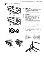
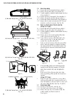
(Fig. 8)
4
JACK Unit
4-1
Remove the music rest assembly. (See procedure 1.)
4-2
Remove the speaker grille. (See procedure 2.)
4-3
Turn the speaker box assembly backwards and turn it up.
(See procedure 3.)
4-4
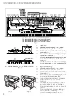
Remove the five [5] screws marked [48e]. The jack
unit can then be removed.
*
After removing the jack unit, remove the following
screws. Each circuit board can then be removed.
(See Fig. 7)
A-JACK circuit board: Four [4] screws marked [4a]
D-JACK circuit board: Eight [8] screws marked [4b]
5
Keycover Assembly
5-1
Remove the music rest assembly. (See procedure 1.)
5-2
Remove the speaker grille. (See procedure 2.)
5-3
Turn the speaker box assembly backwards and turn it up.
(See procedure 3.)
5-4
Remove the two [2] screws marked [46]. The rack
cover can then be removed. (See Fig. 6)
5-5
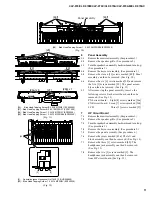
Set the left end of the rot at the slits of the guide
and then lift the rear keycover assembly.
(See Fig. 8)
5-6
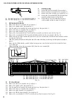
Lean slightly the keycover assembly so that the rot
can be removed from the guide rail. (See Fig. 9)
When removing, be sure not to make scratches on the
sideboard.
*
When reinstalling the keycover assembly, apply a
masking shield tape around the guide rail to
prevent from making scratches on the ass'y.
(Fig. 9)
[4]:
Bind Head Tapping Screw-B 3.0X8 MFZN2BL (EP600190)
[45]: Bind Head Tapping Screw-1 3.5X20 MFZN2Y (EP030470)
[46]: Bind Head Tapping Screw-B 3.0X8 MFZN2BL (EP600190)
[48]: Bind Head Tapping Screw-1 3.5X12 MFZN2BL (EP030340)
(Fig. 6)
[4]:
Bind Head Tapping Screw-B 3.0X8 MFZN2BL (EP600190)
(Fig. 7)
DM Cover Assembly
DM
SWX-A
SWX-XG
SWX-C
SWX-E
SWX-F
NETWORK
MA120
FU120L
A-JACK
D-JACK
[46a]
[46b]
[89]x4
[45]
[48a]
[48b]
[48c]
[48d]
[48d]
[48a]
[48b]
[48e]
[48e]
[4a]
[4b]
Transformer
[44]
[46]
Shilde cover assembly
A-JACK
D-JACK
[4a]
[4b]
[4b]
Angle, Jack


