


–12–
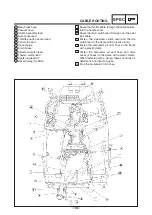
N Route the wireharness through the guide.
O Place the speed sensor lead between the ribs of
the air filter case.
P Fasten the lean angle cut-off switch lead to the stay
(2 locations). Face the end of the band downward.
Q Hang the wireharness and seat lock cable on the
wire holder.
R Fasten the battery negative lead and the starter
motor lead to the frame with a plastic clamp.
S Route the battery negative lead and the fuse box
lead from the box opening to the bottom of the
cross pipe.
T Pass the black seat lock cable beneath the battery
negative lead and starter motor lead and out to the
inside of the frame.
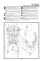
H Install the box light to the box 1.
I Fasten the auto choke leads (left and right) and
throttle position sensor lead to the frame with a
clamp.
Leave some slack in the lead wires so that when
the vacuum hose is install it does not press against
them.
J Fasten the auto choke leads (left and right) to the
frame with a plastic clamp.
K Pass the auto choke lead (right side) and throttle
position sensor lead by the front bottom side of the
vacuum hose.
L Route the thermo switch lead through the guide.
M Insert the air vent hose through the hole on the left
side of the frame bracket.
Align the white paint mark with the end face of hole.
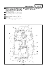
CABLE ROUTING
SPEC
Содержание 5GJ5
Страница 1: ......
Страница 34: ... 28 SIGNAL SYSTEM ELEC SIGNAL SYSTEM CIRCUIT DIAGRAM for EUR ...


