FUEL INJECTION SYSTEM
9-35
5. Item
The item names of the detected malfunction are displayed.
6. Condition
The current conditions are displayed. (Detected/Recovered)
7. Symptom
The symptoms of the detected malfunction are displayed.
8. Diagnosis code
The diagnosis codes related to the detected malfunction are displayed.
9. FFD (only for models that can display freeze frame data)
The mark “ ” is displayed when the freeze frame data is available.
10.ECU conduction time (hour: minute: second)
The total ECU conduction time (total hours the vehicle’s main switch was ON) when the malfunction
was detected is displayed.
11.Number of main switch operation after detection
The number of times the main switch was turned on between the malfunction detection and code
reading is displayed.
12.Number of occurrences
The number of malfunction occurrences between the malfunction detection and code reading is dis-
played.
EBS30281
TROUBLESHOOTING DETAILS (FUEL INJECTION SYSTEM)
This section describes the measures per fault code number displayed on the Yamaha diagnostic tool
or multi-function meter display. Check and service the items or components that are the probable cause
of the malfunction following the order given.
After the check and service of the malfunctioning part has been completed, reset the Yamaha diagnos-
tic tool or multi-function meter display according to the “Confirmation of service completion”.
Fault code No.:
Fault code number displayed on the Yamaha diagnostic tool or multi-function meter when the engine
failed to work normally.
Diagnostic code No.:
Diagnostic code number to be used when the diagnostic mode is operated.
Refer to “SELF-DIAGNOSTIC FUNCTION AND DIAGNOSTIC CODE TABLE” on page 10-7.
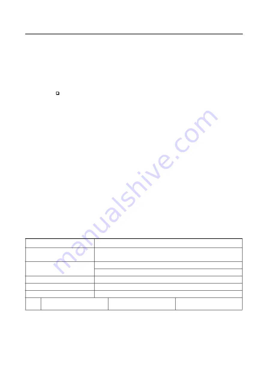
Fault code No. 12
Fault code No.
12
Item
Crankshaft position sensor: no normal signals are received from the
crankshaft position sensor.
Fail-safe system
Unable to start engine
Unable to drive vehicle
Diagnostic code No.
—
Indicated
—
Procedure
—
Item
Probable cause of malfunc-
tion and check
Maintenance job
Confirmation of service com-
pletion
Содержание 2016 Grizzly yfm700gplg
Страница 6: ......
Страница 8: ......
Страница 11: ...IDENTIFICATION 1 2 ...
Страница 37: ...ENGINE SPECIFICATIONS 2 6 Air induction system Solenoid resistance 18 22 Ω ...
Страница 58: ...LUBRICATION SYSTEM CHART AND DIAGRAMS 2 27 EBS30023 LUBRICATION DIAGRAMS 6 7 8 9 3 4 3 2 1 5 ...
Страница 60: ...LUBRICATION SYSTEM CHART AND DIAGRAMS 2 29 1 2 3 4 5 ...
Страница 62: ...COOLING SYSTEM DIAGRAMS 2 31 EBS20021 COOLING SYSTEM DIAGRAMS 1 2 3 10 9 8 6 7 5 4 ...
Страница 72: ...CABLE ROUTING 2 41 Engine right side view 2 C E 1 9 10 E 1 9 10 E 5 6 9 A B C D 1 2 3 4 5 6 7 8 ...
Страница 76: ...CABLE ROUTING 2 45 Engine top view B 5 6 7 8 9 10 11 12 13 14 15 16 17 A 1 2 3 4 19 20 21 22 C 18 11 17 17 ...
Страница 78: ...CABLE ROUTING 2 47 Front and rear brake hoses F 3 F 3 F 3 3 I G H 4 4 B C D 2 E D 2 A 1 ...
Страница 80: ...CABLE ROUTING 2 49 ...
Страница 83: ......
Страница 119: ...PERIODIC MAINTENANCE 3 36 A Headlight left and right B Handle mounted light b a 1 A b a 1 B ...
Страница 120: ...PERIODIC MAINTENANCE 3 37 ...
Страница 183: ...STEERING STEM 4 60 TIP Align the punch mark a on the EPS unit with the groove b in the pitman arm 1 b a ...
Страница 197: ...REAR ARMS AND REAR SHOCK ABSORBER ASSEMBLIES 4 74 7 9 8 9 7 3 5 4 5 3 6 2 10 10 1 ...
Страница 198: ...REAR ARMS AND REAR SHOCK ABSORBER ASSEMBLIES 4 75 ...
Страница 203: ...ENGINE INSPECTION 5 2 Top cover Refer to GENERAL CHASSIS 2 on page 4 6 ...
Страница 244: ...ELECTRIC STARTER 5 43 a b b 1 2 3 ...
Страница 316: ...AIR INDUCTION SYSTEM 7 9 EBS20057 AIR INDUCTION SYSTEM 3 4 1 2 3 4 1 2 ...
Страница 352: ...REAR CONSTANT VELOCITY SHAFT ASSEMBLIES FINAL DRIVE ASSEMBLY AND REAR DRIVE SHAFT 8 31 ...
Страница 355: ......
Страница 365: ...ELECTRIC STARTING SYSTEM 9 10 ...
Страница 369: ...CHARGING SYSTEM 9 14 ...
Страница 417: ...FUEL PUMP SYSTEM 9 62 ...
Страница 432: ...ELECTRICAL COMPONENTS 9 77 EBS20084 ELECTRICAL COMPONENTS 4 5 6 7 8 9 10 11 12 13 14 15 16 17 19 18 1 2 3 ...
Страница 434: ...ELECTRICAL COMPONENTS 9 79 1 2 3 5 7 8 9 10 11 12 13 14 15 16 17 18 19 4 6 ...
Страница 454: ...ELECTRICAL COMPONENTS 9 99 ...
Страница 461: ...TROUBLESHOOTING 10 6 Too many electrical accessories Incorrect connection Faulty tail brake light assembly ...
Страница 468: ......
Страница 469: ......
Страница 470: ......


