background image

1-9

CHECKING THE CONNECTIONS

GEN

INFO

NOTE:

NOTE:

NOTE:

EAS00026

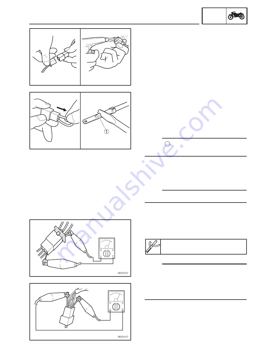
CHECKING THE CONNECTIONS

Check the leads, couplers, and connectors for
stains, rust, moisture, etc.
1. Disconnect:

S

lead

S

coupler

S

connector

2. Check:

S

lead

S

coupler

S

connector
Moisture 

!

 Dry with an air blower.

Rust / stains 

!

 Connect and disconnect sev-

eral times.

3. Check:

S

all connections
Loose connection 

!

 Connect properly.

If the pin 

1

 on the terminal is flattened, bend it

up.

4. Connect:

S

lead

S

coupler

S

connector

Make sure all connections are tight.

5. Check:

S

continuity
(with the pocket tester)

Pocket tester

90890-03112, YU-3112

S

If there is no continuity, clean the terminals.

S

When checking the wire harness, perform
steps (1) to (3).

S

As a quick remedy, use a contact revitalizer
available at most part stores.

Содержание 2002 YZF-R6R

Страница 1: ......

Страница 2: ...ANUAL 2002 by Yamaha Motor Corporation U S A First edition December 2002 All rights reserved Any reproduction or unauthorized use without the written permission of Yamaha Motor Corporation U S A is expressly prohibited Printed in U S A P N LIT 11616 16 45 ...

Страница 3: ...s policy is intended to provide the customer with the most satisfaction from his vehicle and to conform to federal environmental quality objectives Yamaha Motor Company Ltd is continually striving to improve all of its models Modifications and sig nificant changes in specifications or procedures will be forwarded to all authorized Yamaha dealers and will appear in future editions of this manual wh...

Страница 4: ...he top of each page except in Chapter 3 PERIODIC CHECKS AND ADJUSTMENTS where the sub section title s ap pears 3 Sub section titles appear in smaller print than the section title 4 To help identify parts and clarify procedure steps there are exploded diagrams at the start of each removal and disassembly section 5 Numbers are given in the order of the jobs in the exploded diagram A circled number i...

Страница 5: ...trical system 9 Troubleshooting Symbols 10 to 17 indicate the following 10 Serviceable with engine mounted 11 Filling fluid 12 Lubricant 13 Special tool 14 Tightening torque 15 Wear limit clearance 16 Engine speed 17 Electrical data Symbols 18 to 23 in the exploded diagrams indi cate the types of lubricants and lubrication points 18 Engine oil 19 Gear oil 20 Molybdenum disulfide oil 21 Wheel beari...

Страница 6: ...FICATIONS PERIODIC CHECKS AND ADJUSTMENTS CHASSIS ENGINE COOLING SYSTEM FUEL INJECTION SYSTEM ELECTRICAL SYSTEM TROUBLESHOOTING GEN INFO 1 SPEC 2 3 ENG 4 COOL 5 FI 6 CHAS 7 ELEC 8 TRBL SHTG 9 CHK ADJ EAS00012 TABLE OF CONTENTS ...

Страница 7: ...CK WASHERS PLATES AND COTTER PINS 1 8 BEARINGS AND OIL SEALS 1 8 CIRCLIPS 1 8 CHECKING THE CONNECTIONS 1 9 SPECIAL TOOLS 1 10 CHAPTER 2 SPECIFICATIONS GENERAL SPECIFICATIONS 2 1 ENGINE SPECIFICATIONS 2 2 CHASSIS SPECIFICATIONS 2 11 ELECTRICAL SPECIFICATIONS 2 15 CONVERSION TABLE 2 18 GENERAL TIGHTENING TORQUE SPECIFICATIONS 2 18 TIGHTENING TORQUES 2 19 ENGINE TIGHTENING TORQUES 2 19 CHASSIS TIGHTE...

Страница 8: ...EARANCE 3 10 SYNCHRONIZING THE THROTTLE BODIES 3 16 ADJUSTING THE ENGINE IDLING SPEED 3 18 ADJUSTING THE THROTTLE CABLE FREE PLAY 3 19 CHECKING THE SPARK PLUGS 3 21 MEASURING THE COMPRESSION PRESSURE 3 22 CHECKING THE ENGINE OIL LEVEL 3 24 CHANGING THE ENGINE OIL 3 25 MEASURING THE ENGINE OIL PRESSURE 3 27 ADJUSTING THE CLUTCH CABLE FREE PLAY 3 29 CLEANING THE AIR FILTER ELEMENT 3 30 CLEANING THE ...

Страница 9: ...ATING THE CABLES 3 58 LUBRICATING THE LEVERS AND PEDALS 3 58 LUBRICATING THE SIDESTAND 3 58 LUBRICATING THE REAR SUSPENSION 3 58 ELECTRICAL SYSTEM 3 59 CHECKING AND CHARGING THE BATTERY 3 59 CHECKING THE FUSES 3 64 REPLACING THE HEADLIGHT BULBS 3 66 ADJUSTING THE HEADLIGHT BEAMS 3 67 CHAPTER 4 CHASSIS FRONT WHEEL AND BRAKE DISCS 4 1 REMOVING THE FRONT WHEEL 4 3 CHECKING THE FRONT WHEEL 4 3 CHECKIN...

Страница 10: ...ALIPER 4 36 DISASSEMBLING THE FRONT BRAKE CALIPERS 4 38 DISASSEMBLING THE REAR BRAKE CALIPER 4 39 CHECKING THE FRONT AND REAR BRAKE CALIPERS 4 40 ASSEMBLING AND INSTALLING THE FRONT BRAKE CALIPERS 4 41 ASSEMBLING AND INSTALLING THE REAR BRAKE CALIPER 4 43 FRONT FORK 4 45 FRONT FORK LEGS 4 45 REMOVING THE FRONT FORK LEGS 4 48 DISASSEMBLING THE FRONT FORK LEGS 4 49 CHECKING THE FRONT FORK LEGS 4 50 ...

Страница 11: ...ING THE DRIVE CHAIN 4 76 CHECKING THE SWINGARM 4 76 CHECKING THE DRIVE CHAIN 4 77 INSTALLING THE SWINGARM 4 79 CHAPTER 5 OVERHAULING THE ENGINE ENGINE 5 1 DRIVE SPROCKET 5 1 EXHAUST PIPE 5 2 LEADS AND HOSES 5 3 ENGINE 5 5 INSTALLING THE ENGINE 5 6 CAMSHAFTS 5 8 CYLINDER HEAD COVER 5 8 CAMSHAFTS 5 9 REMOVING THE CAMSHAFTS 5 10 CHECKING THE CAMSHAFTS 5 11 CHECKING THE TIMING CHAIN CAMSHAFT SPROCKETS...

Страница 12: ...NG THE GENERATOR 5 36 SHIFT SHAFT 5 38 SHIFT SHAFT AND STOPPER LEVER 5 38 CHECKING THE SHIFT SHAFT 5 40 CHECKING THE STOPPER LEVER 5 40 INSTALLING THE SHIFT SHAFT 5 40 CRANKSHAFT POSITION SENSOR AND PICKUP ROTOR 5 41 REMOVING THE PICKUP ROTOR 5 43 INSTALLING THE PICKUP ROTOR 5 43 CLUTCH 5 45 CLUTCH COVER 5 45 CLUTCH 5 47 REMOVING THE CLUTCH 5 48 CHECKING THE FRICTION PLATES 5 48 CHECKING THE CLUTC...

Страница 13: ...64 ASSEMBLING THE CRANKCASE 5 64 CONNECTING RODS AND PISTONS 5 66 REMOVING THE CONNECTING RODS AND PISTONS 5 67 REMOVING THE CRANKSHAFT ASSEMBLY 5 68 CHECKING THE CYLINDER AND PISTON 5 68 CHECKING THE PISTON RINGS 5 69 CHECKING THE PISTON PINS 5 70 CHECKING THE BIG END BEARINGS 5 71 INSTALLING THE CONNECTING ROD AND PISTON 5 74 CRANKSHAFT 5 78 CHECKING THE CRANKSHAFT 5 79 CHECKING THE CRANKSHAFT J...

Страница 14: ... INJECTION SYSTEM 7 1 WIRING DIAGRAM 7 2 ECU S SELF DIAGNOSTIC FUNCTION 7 3 ALTERNATE INSTRUCTIONS OPERATION CONTROL FAIL SAFE ACTION 7 4 FAIL SAFE ACTIONS TABLE 7 4 TROUBLESHOOTING CHART 7 5 DIAGNOSTIC MODE 7 6 TROUBLESHOOTING DETAILS 7 12 THROTTLE BODIES 7 27 CHECKING THE INJECTOR 7 31 CHECKING THE THROTTLE BODY 7 31 CHECKING THE PRESSURE REGULATOR 7 32 CHECKING THE FUEL PUMP AND PRESSURE REGULA...

Страница 15: ... 8 9 ELECTRIC STARTING SYSTEM 8 14 CIRCUIT DIAGRAM 8 14 STARTING CIRCUIT CUT OFF SYSTEM OPERATION 8 15 TROUBLESHOOTING 8 16 STARTER MOTOR 8 19 CHECKING THE STARTER MOTOR 8 21 ASSEMBLING THE STARTER MOTOR 8 22 CHARGING SYSTEM 8 23 CIRCUIT DIAGRAM 8 23 TROUBLESHOOTING 8 24 LIGHTING SYSTEM 8 26 CIRCUIT DIAGRAM 8 26 TROUBLESHOOTING 8 28 CHECKING THE LIGHTING SYSTEM 8 30 SIGNALING SYSTEM 8 33 CIRCUIT D...

Страница 16: ...INE 9 2 FUEL SYSTEM 9 2 ELECTRICAL SYSTEMS 9 2 POOR MEDIUM AND HIGH SPEED PERFORMANCE 9 2 ENGINE 9 2 FUEL SYSTEM 9 2 FAULTY GEAR SHIFTING 9 3 SHIFTING IS DIFFICULT 9 3 SHIFT PEDAL DOES NOT MOVE 9 3 JUMPS OUT OF GEAR 9 3 FAULTY CLUTCH 9 3 CLUTCH SLIPS 9 3 CLUTCH DRAGS 9 3 OVERHEATING 9 4 ENGINE 9 4 COOLING SYSTEM 9 4 FUEL SYSTEM 9 4 CHASSIS 9 4 ELECTRICAL SYSTEMS 9 4 OVERCOOLING 9 4 COOLING SYSTEM ...

Страница 17: ...T DOES NOT COME ON 9 6 HEADLIGHT BULB BURNT OUT 9 6 TAIL BRAKE LIGHT DOES NOT COME ON 9 6 TAIL BRAKE LIGHT BULB BURNT OUT 9 6 TURN SIGNAL DOES NOT COME ON 9 6 TURN SIGNAL BLINKS SLOWLY 9 6 TURN SIGNAL REMAINS LIT 9 6 TURN SIGNAL BLINKS QUICKLY 9 6 HORN DOES NOT SOUND 9 6 ...

Страница 18: ...OTORCYCLE IDENTIFICATION EAS00017 VEHICLE IDENTIFICATION NUMBER The vehicle identification number 1 is stamped into the right side of the steering head pipe EAS00018 MODEL LABEL The model label 1 is affixed to the frame This information will be needed to order spare parts ...

Страница 19: ...the fuel volume requirement varies by the engine operating conditions such as acceleration deceleration or operating under a heavy load Carburetors that me ter the fuel through the use of jets have been provided with various auxiliary devices so that an opti mum air fuel ratio can be achieved to accommodate the constant changes in the operating conditions of the engine As the requirements for the ...

Страница 20: ... be injected into the intake manifold only during the time the passage remains open Therefore the longer the length of time the injector is energized injection duration the greater the volume of fuel that is supplied Conversely the shorter the length of time the injector is ener gized injection duration the lesser the volume of fuel that is supplied The injection duration and the injection timing ...

Страница 21: ...llowing order ODO TRIP 1 TRIP 2 ODO If the fuel level warning light comes on the odometer display will automatically change to the fuel re serve tripmeter mode F TRIP and start counting the distance traveled from that point In that case pushing the SELECT button switches the display between the various tripmeter and odometer modes in the following order F TRIP TRIP 1 TRIP 2 ODO F TRIP To reset a t...

Страница 22: ... is started before completing the procedure only the settings made before the SELECT button was last pushed will be applied SIn this mode the multi function display shows the current setting for each function except the shift timing indicator light activity function To adjust the display brightness 1 Turn the key to OFF 2 Push and hold the SELECT button 3 Turn the key to ON and then after five sec...

Страница 23: ...ight deactivation function SThe indicator light deactivation function can be set between 7 000 and 12 000 r min in increments of 500 r min SBe sure to set the deactivation function to a higher engine speed than for the activation function otherwise the shift timing indicator light will remain deactivated 1 Push the RESET button to select the desired engine speed for deactivating the indicator ligh...

Страница 24: ...sassembly clean all of the parts and place them in trays in the order of disas sembly This will speed up assembly and al low for the correct installation of all parts 5 Keep all parts away from any source of fire EAS00021 REPLACEMENT PARTS Use only genuine Yamaha parts for all replace ments Use oil and grease recommended by Yamaha for all lubrication jobs Other brands may be similar in function an...

Страница 25: ...s are visible When installing oil seals lubricate the oil seal lips with a light coat of lithium soap based grease Oil bearings liberally when installing if appropriate 1 Oil seal Do not spin the bearing with compressed air because this will damage the bearing sur faces 1 Bearing EAS00025 CIRCLIPS Before reassembly check all circlips carefully and replace damaged or distorted circlips Al ways repl...

Страница 26: ... Connect and disconnect sev eral times 3 Check Sall connections Loose connection Connect properly If the pin 1 on the terminal is flattened bend it up 4 Connect Slead Scoupler Sconnector Make sure all connections are tight 5 Check Scontinuity with the pocket tester Pocket tester 90890 03112 YU 3112 SIf there is no continuity clean the terminals SWhen checking the wire harness perform steps 1 to 3 ...

Страница 27: ...ed to remove the generator ro tor 90890 01701 YS 01880 A Sheave holder This tool is used to hold the generator rotor when removing or installing the generator ro tor bolt or pickup coil rotor bolt 90890 01304 YU 01304 Piston pin puller This tool is used to remove the piston pins Radiator cap tester 90890 01325 YU 24460 01 Adapter 90890 01352 YU 33984 Radiator cap tester Adapter These tools are use...

Страница 28: ...l and dust seal Vacuum gauge 90890 03094 YU 08030 Vacuum gauge This gauge is used to synchronize the carbu retors Compression gauge 90890 03081 YU 33223 Adapter 90890 04136 Compression gauge Adapter These tools are used to measure engine compression 90890 03112 YU 3112 Pocket tester This tool is used to check the electrical sys tem Oil pressure gauge 90890 03153 YU 03153 Adapter 90890 03139 Oil pr...

Страница 29: ...chanical seal installer 90890 04078 YM 33221 Middle driven shaft bearing driver Mechanical seal installer These tools are used to install the water pump seal 90890 04086 YM 91042 Clutch holding tool This tool is used to hold the clutch boss when removing or installing the clutch boss nut 90890 04101 Valve lapper This tool is needed to remove and install the valve lifter 90890 04111 Valve guide rem...

Страница 30: ...e Function Illustration 90890 06756 YB 35956 Vacuum pressure pump gauge set This tool used to measure the vacuum pres sure 90890 85505 ACC 11001 05 01 Yamaha bond No 1215 This bond is used to seal two mating surfaces e g crankcase mating surfaces ...

Отзывы: