37
Tyros2
NITOR SPEAKER
RS-MS02
ER’S MANUAL
ENUNGSANLEITUNG
E D’EMPLOI
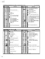
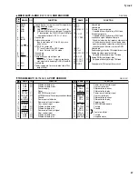
PIN
No.
NAME
I/O
FUNCTION
PIN
No.
NAME
I/O
FUNCTION
1
2
3
4
5
6
7
8
9
10
11
12
GND1
R-IN
G-IN
B-IN
N.C.
fsc-IN
NTSC/PAL-IN
N.C.
N.C.
CSYNC-N
N.C.
Vcc1
-
I
-
I
I
-
-
I
-
-
Ground Pin for circuits other than 75
Ω
output driver
Analog RGB input pins
With CSYNC-IN at the "L" level, the R-IN,
G-IN and B-IN pins are clamped. During the
"L" level period, the R-IN,G-IN and B-IN pins
input pedestal levels. (100% = 1 Vp-p)
Unused pin
Subcarrier input pin
Inputs sine wave of 1.0 to 5.0 Vp-p or a
pulse carrier.
NTSC/PAL sector pin
"H" level: Selects the NTSC mode.
"L" level: Selects the PAL mode.
Unused pin
Unused pin
Composite sync signal input pin
CSYNC-IN = "L" level : Outputs a composite
sync signal while clamping R-IN,G-IN and B-IN.
Unused pin
Power-supply pin for circuits other than 75
Ω
output driver.
13
14
15
16
17
18
19
20
21
22
23
24
Unused pin
Unused pin
Chroma signal output pin
Capable of directly driving a 75
Ω
load.
Y-signal output pin
Capable of directly driving a 75
Ω
load.
Luminance signal band control pin
Capable of adjusting the frequency characteristic
of the luminance signal at the composite video
signal output pin by connecting a capacitor or a
capacitor and an inductor in series to GND1.
Unused pin
Power-supply pin for the 75
Ω
output driver circuit
Composite video signal output pin
Capable of directly driving a 75
Ω
load.
Analog RGB signal output pins
Capable of directly driving a 75
Ω
load.
Ground pin for 75
Ω
output driver circuit
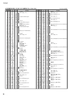
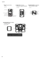
MB3516APF-G-BND
(X2314A00)
RGB ENCODER
N.C.
N.C.
CROMA-OUT
Y-OUT
Y-TRAP
N.C.
Vcc2
VIDEO-OUT
B-OUT
G-OUT
R-OUT
GND2
-
-
O
O
-
-
-
O
O
-
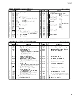
PIN
NO.
I/O
FUNCTION
NAME
PIN
NO.
I/O
FUNCTION
NAME
1
2
3
4
5
6
7
8
9
10
11
12
13
14
15
16
DP0
DM0
V
CC
RESET
EECLK
EEDATA/GANGED
GND
BUSPWR
PWRON1
OVRCUR1
DM1
DP1
PWRON2
OVRCUR2
DM2
DP2
I/O
I/O
-
I
O
I/O
-
I
O
I
I/O
I/O
O
I
I/O
I/O
Differential data plus
Differential data minus
Power supply
Reset
EEPROM serial clock
EEPROM serial data / Power management mode indicator
Ground
Power source indicator
Power-on/-off control signal
Over-current input
Differential data minus
Differential data plus
Power-on/-off control signal
Over-surrent input
Differential data minus
Differential data plus
17
18
19
20
21
22
23
24
25
26
27
28
29
30
31
32
PWRON3
OVRCUR3
DM3
DP3
PWRON4
OVRCUR4
DM4
DP4
V
CC
EXTMEM
TSTPLL
GND
XTAL2
XTAL1
TSTMODE
SUSPND
O
I
I/O
I/O
O
I
I/O
I/O
-
I
I/O
-
O
I
I
O
Power-on/-off control signal
Over-current input
Differential data minus
Differential data plus
Power-on/-off control signal
Over-current input
Differential data minus
Differential data plus
Power supply
EEPROM read enable
Test pin
Ground
Crystal oscillator
Test pin
Suspend status
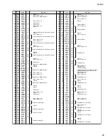
TUSB2046BVF
(X4704A00)
4-PORT USB HUB
Содержание 2
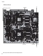
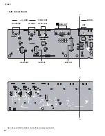
Страница 47: ...47 Tyros2 2NA WE84370 2 2 F F to DAC2A CN101 to LCL CN1 to AJK CN7 Pattern Side ...
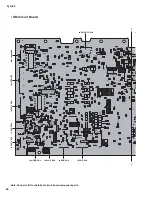
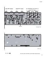
Страница 57: ...57 Tyros2 Note See parts list for details of circuit board component parts P P Pattern Side 2NA WE81690 4 ...
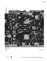
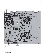
Страница 61: ...61 Tyros2 Note See parts list for details of circuit board component parts R R Pattern Side 2NA WE81690 4 ...
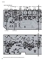
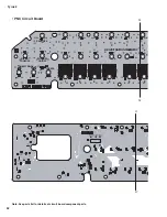
Страница 64: ...64 Tyros2 Note See parts list for details of circuit board component parts PNR Circuit Board T T ...


