background image


5


5.2 Maintenance and Inspection 

For lubrication of the pump, perform oiling once every 10 days with 
lubricating oil. (Fig. 6) 
Supply the lubricating oil as following. 
1)  Remove the air regulator. 
2)  Inject a few drops of lubricating oil (approx. 0.5 mL) into the air supply 

port as shown in the figure at right. Use turbine oil class 1 ISO (VG-32) 
or equivalent as the lubricating oil. 


[Inspection] 
-

  Oil is a fluid and easily polluted. Keep it clean at all times. 

-

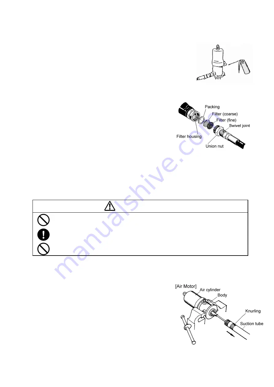
  To protect the flow meter, a filter is installed between the pump and the 

flow meter. If filter clogging occurs, the oil flow is get worse. Clean the 
filter sometimes. (Fig. 7) 

-

  The oil-proof hose is a consumable product. Check it periodically. If any 

blemish or leakage is found, replace the hose a little earlier. 

-

  The packing of the pump will be worn away. Check and replace it at 

least once a year. 


6. Disassembly and Assembly 

-

  When the pump operation becomes defective or stops, do not disassemble the pump thoughtlessly, but refer to 

the item on P.4 (Troubleshooting and Corrective Measures), and judge the condition carefully and disassemble 
only the minimum necessary parts. 

-

  The air motor is rarely touched directly, so its failure rate is very low. The air motor does not need to be 

disassembled. If disassembling is required, ask the dealer to disassemble the air motor. 


WARNING 

-  Gasoline is a high-volatility material. Do not use gasoline to clean the pump in any case, otherwise it 

may cause ignition or explosion. 

-  Before starting disassembling or inspecting the machine, be sure to shut off the supply air and open 

the outlet valve to release the internal pressure of the machine. 

-  When washing parts, do not use such a liquid as corrodes aluminum, copper alloy, iron, etc. 


6.1 Disassembling the Air Motor and the Lower Pump 

1)  Shut off the air that is supplied to the pump and bleed the internal 

pressure of the pump. 

2)  Remove the oil-proof hose and the air hose from the pump.   
3)  Release the 3 clasp on the top of the oil tank upward, and remove 

the lid together with the pump. 

4)  Unscrew the 5 bolts (on the rear side of the lid) that fix the pump 

Assy and the lid and separate the pump Assy from the lid.   
Bleed the oil remaining in the tube by pushing up the ball in the 
foot valve with a finger. 

5)  Fix the air motor body of the pump on the vise and set a pipe 

wrench on the knurling section in the upper part of the suction 
tube of the lower pump and unscrew it. (Fig. 8) 


<NOTE>


The air cylinder is easily blemished. Do not fix it on the vise.   

Fig.6

Fig.7

Fig.8

Содержание SGR-110A5

Страница 1: ...IL LUBRICATOR SGR 110A5 MODEL No 880635 WARNING Prior to operating this pump be sure to read this operation manual for safety After reading the manual please keep it at hand any time for your quick re...

Страница 2: ......

Страница 3: ...nd caution symbols have the meanings described below Be sure to remember their meanings WARNING This indicates the existence of potential hazard which if not avoided will result in death or serious in...

Страница 4: ...Any secondary accident such as pollution of installation due to hose damage or leakage from the valve without shutting off the supply air shall be attributable to the user s responsibility During mach...

Страница 5: ...hine 3 5 Maintenance and Inspection 5 1 Troubleshooting and Corrective Measures 4 5 2 Maintenance and Inspection 5 6 Disassembly and Assembly 6 1 Disassembling the Air Motor and the Lower Pump 5 6 2 D...

Страница 6: ...a lower pump to draw up the material as shown in the figure at right When compressed air is supplied from the compressor to the air motor the air piston starts its up down motion by the function of t...

Страница 7: ...ent 1 Turn the knob of the air regulator counterclockwise to reset the indicator of the pressure gauge to 0 After that connect the air chuck to supply air NOTE Using an air regulator permits adjusting...

Страница 8: ...rtant machine 1 Before starting oil supply be sure to turn the knob of the grip meter counterclockwise to reset to the 0 position If the short needle has not been reset turn the long needle to reset t...

Страница 9: ...any open valve on the material output side Check if the material does not leak at the exhaust port of the air motor The air motor is faulty Ask for servicing the air motor When the outlet side is clo...

Страница 10: ...ed directly so its failure rate is very low The air motor does not need to be disassembled If disassembling is required ask the dealer to disassemble the air motor WARNING Gasoline is a high volatilit...

Страница 11: ...any blemish or wear is found replace the part with a new one 5 Do not disassemble the housing and the connecting rod if possible If they are disassembled assemble them so that the clearance between t...

Страница 12: ...late 1 9 710927 Valve seat 1 10 712018 Cylinder 1 11 683503 Nut 1 12 710912 Valve seat 1 13 712168 Collar 1 14 712175 Adapter 1 15 611101 Bolt 1 No Parts No Description Q ty 1 851755 Pump Assy 1 2 682...

Страница 13: ...006 Spacer 15 59310 001 Totalizer Assembly 16 55212 115 Screw Totalizer Frame 17 59008 001 Packing Gland Kit Buna N 18 13268 000 Cam Standard electronic 19 22872 001 Quad Ring Buna N 20 58959 001 Scr...

Страница 14: ...elow 480 480 953 SGR 110A5 880635 5 x 1 FLUID CONNECTION DISCHARGE PORT Grip meter AIR CONNECTION SUPPLY PORT Coupler plug PS 20PM 0 3 0 7 MPa 87 5 dB ENV TEMPERATURE 0 60 C MATERIAL TEMP 0 80 C 27 5...

Страница 15: ...cause corrosion inflation or dissolution of the component parts of the product 4 Irregularity arising from repair made by other than by our firm our regional office dealer or authorized service perso...

Страница 16: ...Hengelo O The Netherlands PHONE 31 0 74 242 2032 FAX 31 0 74 242 1055 Manufactured by YAMADA CORPORATION INTERNATIONAL DEPARTMENT No 1 3 1 Chome Minami Magome Ohta Ku Tokyo 143 8504 Japan PHONE 81 0 3...

Отзывы: