YAMADA 804354 Скачать руководство пользователя страница 15

- 14 - 


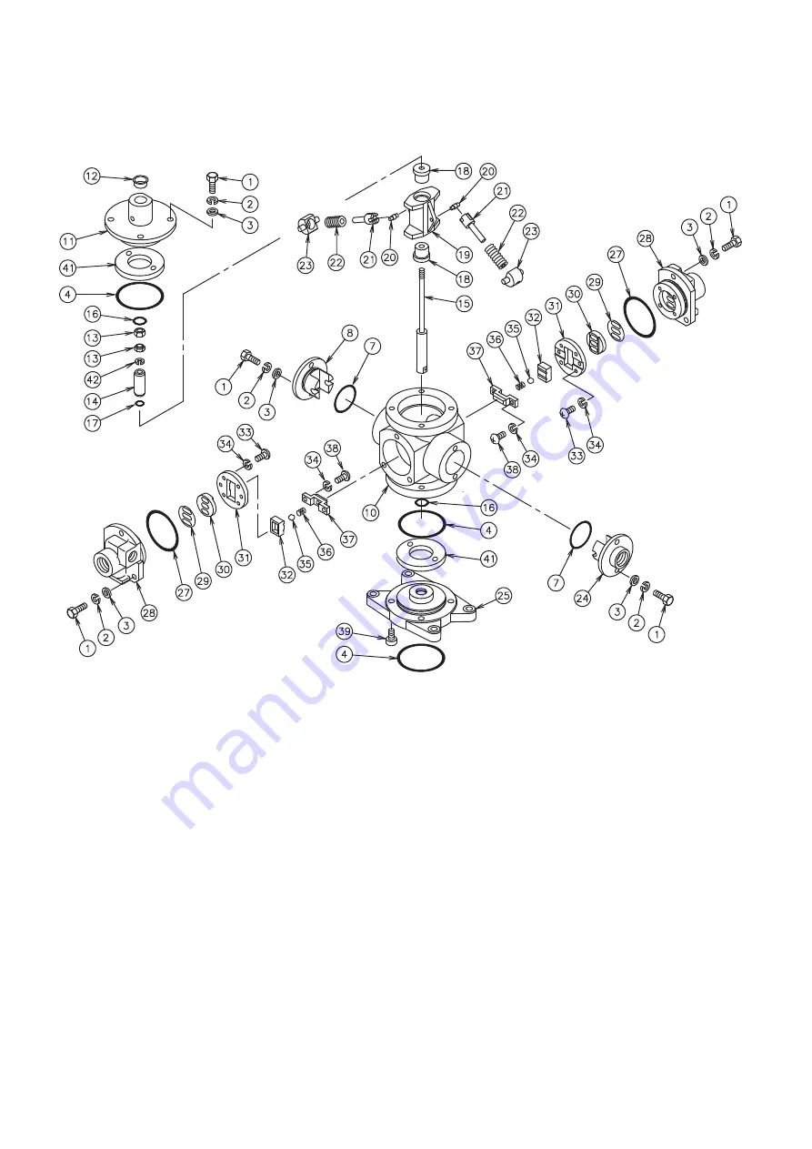
DISASSEMBLY PROCEDURE 

1. 

Remove Bolt (Item 1) from Retainer (Item 8 and 24). 

1-1. Remove Retainer (Item 8 and 24) from Valve Cylinder (Item 

10). 

a. 

Remove O-Ring (Item 7) from Retainer (Item 8 and 24).   

1-2. Remove Spring Guide (Item 23), Spring (Item 22) and Trip 

Arm (Item 21) from Valve Cylinder (Item 10). 

1-3. Remove Pin (Item 20) from Valve Switcher (Item 19). 
 

2. 

Remove Bolt (Item 1) from Valve Body (Item 28). 

2-1. Remove O-Ring (Item 27) from Valve Body (Item 28). 
2-2. Remove Screw (Item 38) from Block Holder (Item 37). 
2-3. Remove Block Holder (Item 37), Spring (Item 36) and Ball 

(Item 35) from Block (Item 32). 

2-4. Remove Block (Item 32) from Block Guide (Item 31). 
2-5. Remove Screw (Item33) from Block Guide (Item 31). 
2-6. Remove Valve Guide (Item 31) from Valve Body (Item 28). 
2-7. Remove Valve Seat (Item 30) and Gasket (Item29) from 

Valve Body (Item 28). 


3. 

Remove Cap (Item 12) from Cap (Item 11). 

3-1. Remove Bolt (Item 1) from Cap (Item 11). 
3-2. Remove Cap (Item 11) from Valve Cylinder (Item 10). 
3-3. Remove O-Rings (Items 4 & 16) and Cushion (item 41) from 

Cap (Item 11). 


4.    Remove Valve Rod Assembly (Item 15) from Valve Cylinder 

(Item 10). 

4-1. Remove Lock Nut (Item 13) from Valve Rod Assembly (Item 

15). 

4-2. Remove Spring Washer (Item 42) and Bushing (Item 14) 

from Valve Rod Assembly (Item 15). 

4-3. Remove O-Ring (Item 17) from Bushing (Item 14). 
 

5. 

Remove Valve Rod Assembly (Item 15), Valve Switcher   

(Item 19) and Bushing (Item 18) from Valve Cylinder (Item 10). 

5-1. Remove Valve Rod Assembly (Item 15) from Valve Switcher 

(Item 19). 

5-2. Remove Bushing (Item 18) from Valve Switcher (Item 19) 


6. 

Remove Bolt (Item 39) from Base Cap (Item 25). 

6-1. Remove O-Ring (Item 4) from both sides of the Base Cap   

(Item 25). 

6-2. Remove O-Ring (Item 16) and Cushion (item 41) from Base 

Cap (Item 25). 
 

7. 

To re-assemble Switching Valve Assembly, reverse 
disassembly procedure. (Refer to illustration for torque 
specifications.) 


SWITCHING VALVE ASSEMBLY (804358) For IP250S20-TE 

EXPLODED VIEW 

Содержание 804354

Страница 1: ...5 E ALGONQUIN RD ARLINGTON HEIGHTS IL 60005 U S A PHONE 1 847 631 9200 FAX 1 847 631 9273 http www yamadapump com Model No 881042 IP140S3 TE 881051 IP140S12 TE 881030 IP200S25 TE 881031 IP250S20 TE TOTE TYPE INK PUMPS WARNING When air is supplied to the pump or when the inner pressure is not decreased completely never put your hand closer to the inlet port of the pump Do not operate with combustib...

Страница 2: ...age or swell the acrylic resin cup To clean the cup do not use wash oil or any other solvent either Install a set of three parts filter regulator and lubricator at the primary air line of the pump However if you install this set at the main air supply line when you use two or more pumps oil may be mainly supplied to the farthest pump without supplying any oil to the other pumps Therefore install t...

Страница 3: ... 109 180 519 1509 205 130 125 4 88 881051 1617 629 65 127 237 283 92 163 522 1509 205 130 125 4 88 881030 1617 629 65 127 237 283 92 163 522 1509 205 130 125 4 88 881031 1617 629 65 127 241 287 97 167 519 1509 205 130 125 4 88 IP140S3 TE 881042 IP140S12 TE 881051 IP200S25 TE 881030 IP250S20 TE 881031 ...

Страница 4: ...nk supply pump for a long time ink overflows mainly because the gland packing is worn out and then ink has accumulated in the collection container This phenomenon indicates when to replace the gland packing with a new one Check to see whether ink is accumulating in the catch bottle periodically SUCKING INK AND REMOVING AIR Close the valve of the delivery pipe and open the bleeder valve of the suct...

Страница 5: ...emoving device to discard it into the waste oil tank Follow Section Filling the oil container to pour new oil from the upper coupler of the oil container into the container until the container is filled half full with oil When you move the the handle of the oil removing device connected to the lower coupler back and forth oil poured into the container is stirred and it cleans the inside of the con...

Страница 6: ... 4 627014 6 Spring Lock Washer 4 631422 7 O ring nitrile 1 640067 8 Pump Holder 1 715140 9 Flange 2 715139 10 Gasket 1 772693 11 Plug 14 mm hex 1 715062 12 Elbow Stand 1 714986 PARTS LIST Item No Description Qty Part No Assembly 804351 1 Spring Guide 50 mm hex 1 713793 2 O ring nitrile 1 640132 3 Backup Ring 2 643705 4 O ring nitrile 2 640045 5 Swivel Body 1 715054 6 Spring 1 713794 7 Ball 1 63048...

Страница 7: ...rom Pump Holder Item 8 3 Remove Pump Holder Item 8 from Elbow Stand Item 12 3 1 Remove O Ring Item 7 from Pump Holder Item 8 4 Remove Gasket Item 10 from Elbow Stand Item 12 5 Remove Plug Item 11 from Elbow Stand Item 12 6 To re assemble TOTE KIT reverse disassembly procedure ELBOW STAND TOTE TYPE EXPLODED VIEW ...

Страница 8: ...1 715001 15 O ring nitrile 2 640152 640163 16 Air Cylinder 1 715142 714995 17 Tube 1 570144 18 Fitting 24 mm hex 1 685450 19 Lower Flange 1 832695 832660 20 Plug 1 634362 21 Split Pin 1 632044 22 Packing 1 686104 23 Socket Bolt 5 mm hex key 3 619101 24 Spring Lock Washer 3 631418 25 Piston Cap 1 713798 26 O ring nitrile 1 640131 27 Trip Rod 1 714996 28 Spring 2 714295 29 Bolt 4 685515 685451 30 Sp...

Страница 9: ...em 40 from Connector Item 39 8 Remove Bolt Item 29 from Upper Flange Item 14 8 1 Remove Upper Flange Item 14 from Air Cylinder Item 16 8 2 Remove O Ring Item 15 from Upper Flange Item 14 9 Remove Air Cylinder Item 16 from Lower Flange Assembly Item 19 10 Remove Piston Assembly Item 33 from Lower Flange Assembly Item 19 11 Remove Socket Bolt Item 23 from Piston Cap Item 25 11 1 Remove Piston Cap It...

Страница 10: ...5 O ring nitrile 2 640169 16 Air Cylinder 1 715387 17 Tube 2 570144 18 Fitting 24 mm hex 2 685450 19 Lower Flange 1 832666 20 Plug 2 634362 21 Split Pin 1 632044 22 Packing 1 686104 23 Socket Bolt 5 mm hex key 3 619101 24 Spring Lock Washer 3 631418 25 Piston Cap 1 713798 26 O ring nitrile 1 640131 27 Trip Rod 1 714996 28 Spring 2 714295 29 Bolt 24 mm hex 4 685451 30 Spring Lock Washer 4 631424 31...

Страница 11: ...emove Union Nut Item 40 from Connector Item 39 8 Remove Bolt Item 29 from Upper Flange Item 14 8 1 Remove Upper Flange Item 14 from Air Cylinder Item 16 8 2 Remove O Ring Item 15 from Upper Flange Item 14 9 Remove Air Cylinder Item 16 from Lower Flange Assembly Item 19 10 Remove Piston Assembly Item 33 from Lower Flange Assembly Item 19 11 Remove Socket Bolt Item 23 from Piston Cap Item 25 11 1 Re...

Страница 12: ...5 8 Retainer 1 714818 29 Gasket 1 772331 9 30 Valve Seat 1 705688 10 Valve Cylinder 1 715113 31 Valve Guide 1 705687 11 Cap 1 714820 32 Block 1 705693 12 Cap 1 685559 33 Screw 4 685942 13 Lock Nut 13 mm hex 1 685454 34 Spring Lock Washer 6 631418 14 Bushing 1 713515 35 Ball 7 32 1 630313 15 Valve Rod 15 mm flats 1 715010 36 Spring 1 706612 16 O ring nitrile 2 640015 37 Block Holder 1 705700 17 O r...

Страница 13: ...11 3 1 Remove Bolt Item 1 from Cap Item 11 3 2 Remove Cap Item 11 from Valve Cylinder Item 10 3 3 Remove O Rings Items 4 16 and Cushion item 41 from Cap Item 11 4 Remove Valve Rod Assembly Item 15 from Valve Cylinder Item 10 4 1 Remove Lock Nut Item 13 from Valve Rod Assembly Item 15 4 2 Remove Spring Washer Item 42 and Bushing Item 14 from Valve Rod Assembly Item 15 4 3 Remove O Ring Item 17 from...

Страница 14: ...iner 1 714818 28 Valve Body 2 715115 9 29 Gasket 2 772331 10 Valve Cylinder 1 715113 30 Valve Seat 2 705688 11 Cap 1 714820 31 Valve Guide 2 705687 12 Cap 1 685559 32 Block 2 705693 13 Lock Nut 13 mm hex 1 685454 33 Screw 8 685942 14 Bushing 1 713515 34 Spring Lock Washer 12 631418 15 Valve Rod 15 mm flats 1 715010 35 Ball 7 32 2 630313 16 O ring nitrile 2 640015 36 Spring 2 706612 17 O ring nitri...

Страница 15: ...om Cap Item 11 3 1 Remove Bolt Item 1 from Cap Item 11 3 2 Remove Cap Item 11 from Valve Cylinder Item 10 3 3 Remove O Rings Items 4 16 and Cushion item 41 from Cap Item 11 4 Remove Valve Rod Assembly Item 15 from Valve Cylinder Item 10 4 1 Remove Lock Nut Item 13 from Valve Rod Assembly Item 15 4 2 Remove Spring Washer Item 42 and Bushing Item 14 from Valve Rod Assembly Item 15 4 3 Remove O Ring ...

Страница 16: ...72330 25 Bottle 1 686106 26 Packing Gland 1 713839 27 Backup Ring 1 684712 28 Packing 1 684713 29 Street Elbow 1 681198 30 Nipple 1 685367 31 Valve 1 685354 32 Body 1 715149 33 Suction Tube 1 715150 34 Valve Stopper 1 715151 35 Spacer 1 715152 36 Valve Seat 1 715153 37 O ring nitrile 1 640144 38 Foot Valve Housing 1 715154 39 O ring nitrile 2 640130 40 Pin 1 685462 41 O ring nitrile 1 640042 42 Pi...

Страница 17: ...sing Item 38 a Remove Back up Ring Item 52 and Packing Item 58 from Foot Valve Item 51 4 4 Remove Valve Seat Item 36 and O Ring Item 37 from Foot Valve Housing Item 38 5 Remove Suction Tube Item 33 from Body Item 32 6 Remove O Ring Item 39 from Piston Valve Item 46 7 Remove Pin Item 79 from Piston Valve Item 46 8 Remove Shovel Rod Item 50 from Piston Valve Item 46 9 Remove Piston Valve Item 46 and...

Страница 18: ... Packing 1 772330 25 Bottle 1 686106 26 Packing Gland 1 715019 715044 27 Backup Ring 1 772694 772698 28 Packing 1 685458 685461 29 Street Elbow 1 681198 30 Nipple 1 685367 31 Valve 1 685354 32 Body 1 715018 715043 33 Suction Tube 1 715020 715045 34 Valve Stopper 1 715022 715047 35 Spacer 1 715023 715048 36 Valve Seat 1 715024 715049 37 O ring nitrile 1 640136 640140 38 Foot Valve Housing 1 715137 ...

Страница 19: ...rom Foot Valve Housing Item 38 a Remove Back up Ring Item 52 and Packing Item 58 from Foot Valve Item 51 4 4 Remove Valve Seat Item 36 and O Ring Item 37 from Foot Valve Housing Item 38 5 Remove Suction Tube Item 33 from Body Item 32 6 Remove O Ring Item 39 from Piston Valve Item 46 7 Remove Pin Item 49 from Piston Valve Item 46 8 Remove Shovel Rod Item 50 from Piston Valve Item 46 9 Remove Piston...

Страница 20: ...er pump replace the damaged part with a new one and tighten the removed screw s securely The pump does not stop Ink leakage from the ink delivery pipe connection Tighten the screw fixed at the malfunctioning section further or replace the damaged part with a new one Ink leakage from the parts connecting section of the suction pump assembly Air leakage form the air motor The screws that connect par...

Отзывы: