Alyza IQ PO4
Commissioning
69
ba76201d03
05/2020
3.3.18 Setting up a connection with the IQ S
ENSOR
N
ET
system
In the delivery condition the IQ S
ENSOR
N
ET
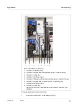
cable (2 m long) is connected to the
ACM control unit of the Alyza IQ and is run to the outside through the bottom
plate.
Connect the IQ S
ENSOR
N
ET
cable of the Alyza IQ to an IQ S
ENSOR
N
ET
module
mounted in the vicinity.
If the Alyza IQ is operated in an IQ S
ENSOR
N
ET
configured minimally, we recom-
mend that you set the terminator switch in the MIQ module (e.g. MIQ/JB) to ON
(see IQ S
ENSOR
N
ET
system operating manual).
Example of a simple IQ S
ENSOR
N
ET
system:
1 TerminalController ( e.g. MIQ/TC 2020 3G),
1 MIQ module (e.g. MIQ/JB),
1 sensor (e.g. Alyza IQ)
8
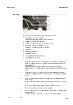
Insert the sample overflow tubes from the overflow vessels into the col-
lection funnel for the sample overflow.
Collection funnel at the foremost cable gland:
(with separate disposal of the chemical waste from the measuring
unit)
or
Collection funnel at the second cable gland:
(with joint disposal of the chemical waste from the measuring unit
and of the sample overflow into the container)
The liquids in the return lines have to be able to drain off freely
(steady slope). Do not immerse the end of the line in water.
9
Check whether the pre-installed sample feed tubes are correctly con-
nected to the filtration pumps and overflow vessels
For detailed information on how to connect the IQ S
ENSOR
N
ET
cable
to an IQ S
ENSOR
N
ET
module mounted in the vicinity please refer to
the IQ S
ENSOR
N
ET
system operating manual, paragraph "Distribut-
ed mounting“.
Содержание WTW Alyza IQ PO4
Страница 171: ......


