8
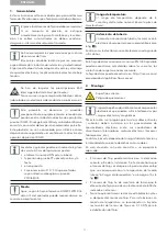
Installation in both horizontal and vertical pipe
sections is possible, however must never be
such that air bubbles can collect in the meter
(see Fig.
2
).
The flow sensor must always be filled with liquid.
Avoid frost at the meter
• We recommend installing the flow sensor in a tilted
position (approx. 45°).
It is recommended that shut-off valves are fitted
upstream and downstream of the flow sensor to
simplify its demounting.
When demounting, an open-ended spanner must be
used on the bottom of the sensor (see Fig.
4
).
3. Power supply
3.1 Battery
In the standard version, a 3.0 VDC lithium battery is inte-
grated that has up to 12 years life (configuration depen-
dent).
• The battery must not be recharged or short-circuited.
• Ambient temperatures below 35 °C have a positive
effect on battery lifetime.
3.2 External power supply
(e.g. via meter electronics)
• Power supply 3.0 … 5.5 VDC
• Power consumption < 100 mAh per year
• Pulse current < 10 mA
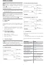
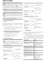
4. Connection diagram
The function of the individual coloured cables
are shown in the following illustrations.
Damages or failure of the meter can occur, if the
cables are reversed or wrongly connected.
4.1 Battery operation
High resolution test
pulse
Useful pulse
yellow
white
GND blue
N.C. brown
PolluFlow
4.2 Galvanically isolated useful pulse
yellow
white
brown
PolluFlow
Test pulse
Useful pulse
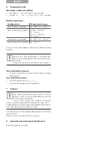
4.3 External power supply 3.0 – 5.5 V
Test pulse
Useful pulse
+ 3 ... 5 V
brown
yellow
white
blue
PolluFlow
5. Communication
The flow sensor has two pulse outputs for connection to
a heat meter.
• Useful pulse
• Test pulse (high resolution for testing laboratories)
The electrical data of the useful pulse are defined
as:
Designation
Value
External power supply
UC < 30 V
Output current
< 20 mA with a residual
voltage of < 0.5 V
Open collector (drain
Cable length to the
partial unit energy meter
< 10 m
Output frequency
battery supplied
< 20 Hz
Output frequency with
external power supply
< 150 Hz
Useful pulse value
10 ml … 5000 l (depend-
ent on the rated value
and power supply)
Pulse duration
1 – 250 ms ± 10 %;
Pulse duration < Pulse
pause
Potential-free contact
(optional)
ENGLISH
GND blue
GND


