


Channel Mapping
is the assignment of a channel to an output port. This
means that output port 'x' will output channel 'y' data.
By default, the channel mapping is set for JR type systems:
(Left/right ailerons)
PORT A1 – channel 2
PORT B1 – channel 6
PORT A2 – channel 2
PORT B2 – channel 6
PORT A3 – channel 2
PORT B3 – channel 6
PORT A4 – channel 2
PORT B4 – channel 6
PORT A5 – channel 2
PORT B5 – channel 6
PORT A6 – channel 2
PORT B6 – channel 6
(elevator/rudder)
PORT C1 – channel 3
PORT C2 – channel 3
PORT C3 – channel 4
PORT C4 – channel 4
PORT C5 – channel 4
PORT C6 – channel 4
PORT C7 – channel 3
PORT C8 – channel 3
(Throttle/ignition kill)
PORT D1 – channel 1
PORT D2 – channel 5
PORT E1 – channel 1
PORT E2 – channel 5
You can of course change the channel mapping for all output ports.
If you have a Futaba system it is recommended that you go to the SYSTEM
MENU, select RESET DEFAULTS and choose the default for the Futaba
system. This will change the channel mapping so that channels 1-4 will be
mapped to the proper output ports for the Futaba system (matching the JR
outputs in functionality).
11
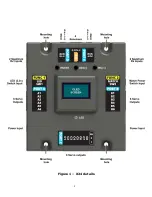
Содержание X24
Страница 8: ...Figure 1 X24 details 8 ...
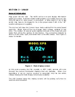
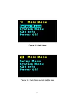
Страница 16: ...Figure 4 Main Menu Figure 5 Main Menu w exit highlighted 16 ...
Страница 18: ...Figure 8 Up arrow more entries available upwards 18 ...
Страница 51: ...Figure 30 X24 Mounting pad template 51 3 30 2 08 ...


