background image


18


XtendLan MUX-1602C 


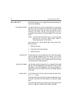
Menu 2 — Toggle Options 

Menu 2 allows you to review and set each of the MUX-1602C 
“toggle”


options. Toggle options have only two settings. To change 

a setting,


position the highlight over it and press the


up arrow


or


down


arrow. The alternate setting appears. 


Alarm Message Display


The Alarm Message Display option enables or disables the on-


screen display of the ALARM message. It toggles as follows: 


ON


– Alarm messages are displayed on the Main Monitor. 


OFF


– Alarm messages are not displayed on the Main 

Monitor. 


The default Alarm Message Display setting is


ON. 


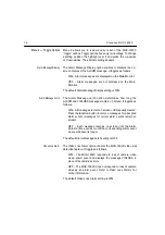
Alarm Message Latch 

The Alarm Message Latch option determines how long the


ALARM and VIDLOSS messages remain on screen. It toggles as


follows: 


ON


– All messages remain on screen until manually cleared.


Press the


function button to remove messages for all


expired


alarm events (messages for current alarm events remain on


screen). 


OFF


– Each message remains on screen until the Alarm


Duration time expires or until the corresponding alarm event


clears, whichever is longer. 


The default Alarm Message Latch setting is


OFF. 


Video Loss Alarm


The Video Loss Alarm option controls the MUX-1602C video loss 

detection feature. It toggles as follows: 


ON


– The MUX-1602C responds to loss of camera video 

as an


alarm event and displays the message VIDLOSS in 

place of


the camera’s picture. 


OFF


– The MUX-1602C does not respond to loss of camera 

video


as an alarm event. Refer to


Video Loss Alarms for 

more


information. 


The default Video Loss Alarm setting is


ON. 

Содержание MUX-1602C

Страница 1: ...MUX 1602C Color screen multiplexer User s Guide...

Страница 2: ...nd used in accordance with the instruc tion manual may cause interference to radio communications It has been tested and found to comply with the limits for a Class A computing device pursuant to subp...

Страница 3: ...d record multiple cameras through the application of digital video multiplexing Dynamic Time Division DTD and Vertical Interval Signal VIS technology Using proprietary DTD technology MUX 1602C multipl...

Страница 4: ...quired Connections 10 Cameras 10 Main Mon Monitor 10 Power 10 Optional Connections 10 Call Mon Monitor 10 VCR In 10 VCR Out 10 S VHS In 11 S VHS Out 11 Alarm 11 Alarm Inputs 11 Alarm Hold Input 11 Ala...

Страница 5: ...R Record Time 20 VCR Alarm Record Time 20 Menu 4 Alarm Duration 21 Menu 5 Global Dwell 21 Menu 6 Camera Titles 22 Motion Detection Setup Screen 22 Menu 7 Security Lock 23 USING THE MUX 1602C 24 Operat...

Страница 6: ...tion Detection 37 How Motion Detection Works 37 Motion Detection Setup 37 Motion Sequencing 38 Alarm Counter 39 SPECIAL APPLICATIONS 40 Simultaneous Record and Play 40 Multiplexed Video Transmission 4...

Страница 7: ...le of Contents continued APPENDIX C IN CASE OF TROUBLE 48 APPENDIX D TECHNICAL SPECIFICATIONS 51 Operating Defaults 51 Video Format 51 Video Level 51 Alarm 52 Display 52 Controls 53 Connectors 53 Elec...

Страница 8: ...ission 5 Figure 4 MUX 1602C System with RS 232 Control 5 Figure 5 MUX 1602C Controls and Indicators 6 Figure 6 MUX 1602C Rear Panel Connectors 8 Figure 7 Alarm Connector 44 Figure 8 Remote Connector 4...

Страница 9: ...acing the MUX 1602C in Setup mode To Engage or Release Security Lock 1 Select the operating mode in which the unit is to be locked 2 Press and hold the function button and press the zoom but ton The M...

Страница 10: ...and full screen viewing Video inputs and outputs provided for both standard and Super VHS video cassette recorders On screen display includes date time alarm status video loss and 10 character camera...

Страница 11: ...cy with which that camera is recorded and displayed In this way recording and display time are dynamically allocated according to the scene activity Motion sensitivity for each camera input can be set...

Страница 12: ...l Signaling VIS techniques to encode system information onto video output to the VCR Time date camera title camera number and alarm status information are placed on the 16 horizontal lines preceding t...

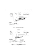
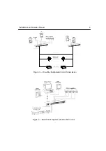
Страница 13: ...4 XtendLan MUX 1602C Figure 1 Basic MUX 1602C System Figure 2 MUX 1602C System with Two VCRs...

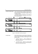
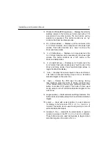
Страница 14: ...Installation and Operation Manual 5 Figure 3 One Way Multiplexed Video Transmission Figure 4 MUX 1602C System with RS 232 Control...

Страница 15: ...llowing paragraphs Figure 5 MUX 1602C Controls and Indicators THE FRONT PANEL Some front panel buttons have dual functions In the descriptions below the primary button function is listed first followe...

Страница 16: ...ght arrow to toggle the time date display 7 live Displays the camera inputs in the current format This button is also used during setup to turn on all motion detection targets on the cursor line 8 tap...

Страница 17: ...provides a composite video signal to the Call Monitor in the full screen format Either one live camera or one or more alarm cameras may be displayed 5 main mon This BNC connector provides a composite...

Страница 18: ...ual 9 10 cam in These BNC connectors accept the composite video output of color or B W cameras Camera input termination is selectable 11 cam out These BNC connectors provide looping camera video from...

Страница 19: ...EIA PAL CCIR compatible video monitor This monitor displays selected live or recorded cameras in any available format This output must be properly terminated Power Connect the MUX 1602C power module...

Страница 20: ...llow the MUX 1602C to be completely integrated with security systems See Alarm Response for details Alarm Inputs MUX 1602C Alarm Inputs accept a contact type or TTL CMOS alarm signal Connect alarm pin...

Страница 21: ...nect remote pin 25 to the output of a compatible source of RS 232 control data Connect the remaining side of the source to ground pin 13 14 or 15 See Remote Connector for details Remote Control Panel...

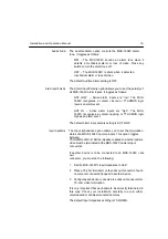
Страница 22: ...he MUX 1602C The procedure is as follows 1 Pressfunction down arrow Internally generated color bars appear on the Main Monitor 2 Turn off any automatic color control features on the monitor that might...

Страница 23: ...omplete the monitor calibration procedure 2 Connect all system cameras directly to the MUX 1602C camera inputs Remove all connections to the looping lower camera outputs 3 Make sure the MUX 1602C is c...

Страница 24: ...xed camera video You may select any viewing mode or display format while recording This will not affect the tape because camera recording and display are independent operations 2 After several minutes...

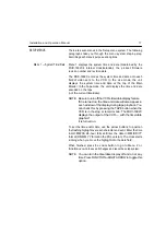
Страница 25: ...ng the option Selecting a Menu Press zoom to go to the next setup menu The next menu appears with the flashing highlight at the first option You can only jump forward through the setup menus If you pr...

Страница 26: ...Be sure to turn offtheVCR s time date display feature If it is turned on the time and date will also appear in each window of the display during tape playback You can check this by pressing the TAPE...

Страница 27: ...M and VIDLOSS messages remain on screen It toggles as follows ON All messages remain on screen until manually cleared Press the function button to remove messages for all expired alarm events messages...

Страница 28: ...pening or TTL CMOS logic high as an alarm event The default alarm input polarity setting is ACT LOW Input Impedance The Input Impedance option allows you to set the termination status of all MUX 1602C...

Страница 29: ...peeds Use the up and down arrows to set each speed NOTE If the MUX 1602C alarm output will not be connected to the VCR s alarm input VCR Record Time and VCR Alarm Record Time should be set to the same...

Страница 30: ...et the camera switching rate The Global Dwell setting determines the rate at which the MUX 1602C sequences cameras in the lower right window of the display or full screen when seq is selected It also...

Страница 31: ...een described below for the current camera Press zoom to set the next camera title If the Camera Titles menu for Camera 16 is displayed presszoom to go to Menu 7 Press a camera button to set that came...

Страница 32: ...t motion target setting and returns to the Camera Titles menu Using the buttons above define those areas of the picture in which motion is to be detected SeeVideo Motion Detectionfor a detailed descri...

Страница 33: ...front panel Press thelive button to view live camera video Thelive light comes on indicating the Main Monitor is displaying camera input video Cameras may be displayed on the Main Monitor in any orde...

Страница 34: ...3 4 x 4 Cameras may be displayed in any order in any of the available views Tape playback and live camera viewing work identically in all respects The MUX 1602C detects recorded alarm events during t...

Страница 35: ...zoom window insert The zoom window contains a one quarter sized view of the current camera overlaid with a movable zoom pointer The zoom pointer indicates the picture area being zoomed and can be mov...

Страница 36: ...ormats Picture In Picture PIP 2 x 2 3 x 3 and 4 x 4 Each display can be composed by selecting the cameras and their location on screen Cameras not already displayed can be sequenced in the lower right...

Страница 37: ...e PIP format is displayed 2 x 2 Format The 2 x 2 format is the familiar quad display It displays four pictures at one time Cameras can be selected for display in any window Cameras not already display...

Страница 38: ...ct button again The select light goes out The MUX 1602C remembers the 3 x 3 camera selection and will recall it the next time the 3 x 3 format is displayed 4 x 4 Format The 4 x 4 format displays 16 pi...

Страница 39: ...ht goes out Sequencing stops with the current camera displayed in the lower right window or full screen Videotape Operations The MUX 1602C allows recording of multiple cameras onto a single videotape...

Страница 40: ...gle priority camera exclusively This feature can be turned on or off at any time To Start Single Camera Recording 1 Press and hold the 1 cam rec function button 2 Press the camera button for the camer...

Страница 41: ...echanical alarm event occurs when there is a contact closure at any MUX 1602C alarm input A video loss alarm occurs when the MUX 1602C detects the loss of video at an active camera input A recorded al...

Страница 42: ...re are multiple alarms the alarm cameras will display in sequence on the Call Monitor 5 Switches the Main Monitor to the highest multicamera format if the alarm camera is not already on display 6 Over...

Страница 43: ...or details When the initial alarm is detected in Tape mode the MUX 1602C does the following 1 Energizes the alarm relay 2 Switches to the VCR Alarm Record Time rate 3 Encodes the camera as alarm and s...

Страница 44: ...input and displays the VIDLOSS message If multiple cameras lose camera input those camera titles will be displayed in sequence on the Call Monitor 4 Switches the Main Monitor to the multicamera forma...

Страница 45: ...1602C detects a recorded alarm while in Tape mode it does the following 1 Flashes the associated camera button light 2 Displays the alarm camera on the Call Monitor overlaid with the ALARM message 3...

Страница 46: ...nts are displayed and captured on videotape How Motion Detection Works The MUX 1602C continuously scans each camera input for video When video is detected the unit captures one video field in digital...

Страница 47: ...f motion is detected at Cameras 5 and 9 then just Camera 5 then at Camera 2 the sequence becomes At point A motion is detected at Camera 5 and Camera 9 The MUX 1602C creates a motion group containing...

Страница 48: ...arm count for each camera input and the time date on which the count was last cleared To Exit the Alarm Counter Screen Press the live button to exit the alarm counter screen The MUX 1602C removes the...

Страница 49: ...in applications that demand continuous video recording of multiple cameras It allows an operator equipped with a second video recorder to review MUX 1602C tapes without interrupting the recording pro...

Страница 50: ...at Site A to the vcr in connector at Site B Both Site A and Site B can view the cameras located at Site A Site B can view either local cameras press live or the cameras located at Site A press functi...

Страница 51: ...Factory Technical Support RS 232 Data The RS 232 remote feature allows the MUX 1602C to be controlled from a computer or ASCII communications terminal see Figure 4 MUX 1602C System with RS 232 The MUX...

Страница 52: ...unctions The effect of a button press is determined by the current status of the unit Determine the status of the MUX 1602C before issuing remote commands because inappropriate commands will be ignore...

Страница 53: ...nput 1 14 Alarm input 14 2 Alarm input 2 15 Alarm input 15 3 Alarm input 3 16 Alarm input 16 4 Alarm input 4 17 Reserved 5 Alarm input 5 18 Ground 6 Alarm input 6 19 Ground 7 Alarm input 7 20 Ground 8...

Страница 54: ...13 14 or 15 PIN NO PIN ASSIGNMENT PIN NO PIN ASSIGNMENT 1 Remote panel 14 Ground 2 Remote panel 15 Ground 3 Remote panel 16 Remote panel 4 Remote panel 17 Remote panel 5 Remote panel 18 Remote panel...

Страница 55: ...1602C installation for either uncontrolled or controlled alarm recording When alarm recording is not controlled the VCR records alarmed cameras as normal video Recorder operation is not affected by a...

Страница 56: ...ct the MUX 1602C vcr in and vcr out connectors to the VCR s video output and video input respectively 2 Connect a wire from the VCR ground to MUX 1602C alarm connector pin 24 alarm output common 3 Con...

Страница 57: ...o save time spend a few minutes getting organized before you pick up the telephone Before calling your Robot dealer or Factory Technical Support write down the following information The serial number...

Страница 58: ...era iris using calibrated monitor Black horizontal lines through picture or picture not stable Camera is double terminated Remove second termination from camera Faulty camera sync or video output Repl...

Страница 59: ...input Serial communications protocol not correct Configure remote device for 1200 bps 1 start bit 8 data bits 1 stop bit no parity Data and data ground connections reversed Reverse data and data groun...

Страница 60: ...splay Live Switcher Select and Sequence off VCR Record Time 24 hours VCR Alarm Record Time 24 hours Alarm Duration 4 seconds Global Dwell 2 seconds Alarm Message Latch Off Video Loss Alarm On Audible...

Страница 61: ...TL CMOS Active High signal Alarm Duration 4 second default Menu selectable from 2 to 999 seconds Alarm Output Normally open NO and normally closed NC contacts with shared common 2 0 A at 30 VDC resist...

Страница 62: ...3 picture display or LEFT function 4 x 4 Right Arrow Selects 4 x 4 picture display or RIGHT function Live Selects camera inputs for viewing Tape Selects VCR input for viewing Seq Sequence Selects sequ...

Страница 63: ...to VCR Camera In BNC Composite video input from camera Camera Out BNC Composite video output from camera passive loop through Electrical Power Requirement 18 Watts center positive 12 VDC Physical Cha...

Отзывы: