background image

Module Programming

Page 7

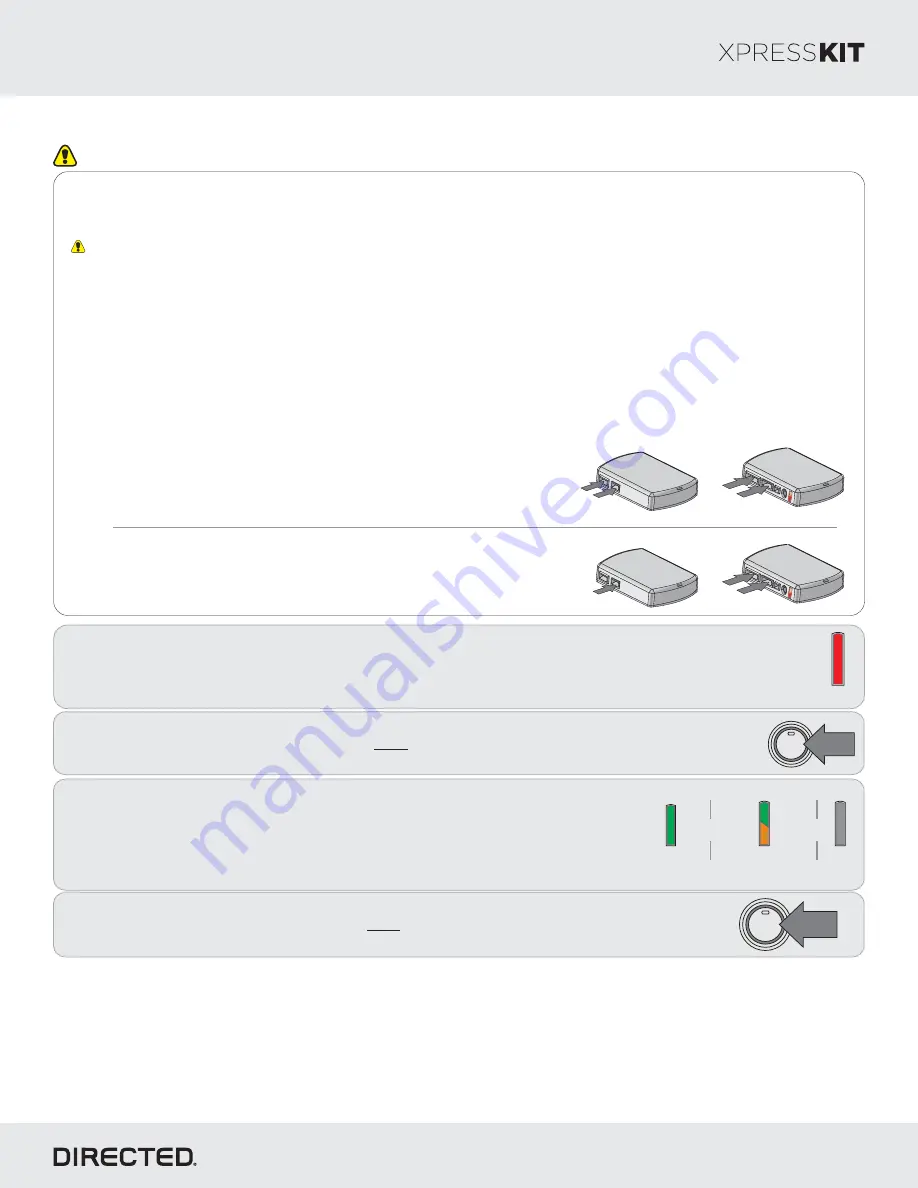
3

Refer to the LED Diagnostics section on pages 8-9 for more information and for troubleshooting purposes.

1

Solid

Wait until the LED turns ON solid red.

Note:

 To skip the transponder programming and use convenience features only, press 

the programming button 5 times. The LED will turn orange then proceed to step 2.

If the transponder programming was skipped

, the LED 

turns ON solid orange for 3 seconds then shuts OFF 
when programming is done.

&

Green or orange

3 seconds

Off

&

2

Press

 the Push-to-Start (PTS) button twice to turn the ignition ON.

Wait for the LED to turn solid green. The LED turns ON for 3 seconds and 
shuts off.

You have successfully completed the module programming sequence.

4

Press 

the Push-to-Start (PTS) button once more to turn on the ignition OFF.

1X

ENGINE

START

STOP

PUSH

Solid green

2X

ENGINE

START

STOP

PUSH

Important

Make all the required connections to the vehicle, as described in the wiring diagram(s) found in this guide, and double check to 
ensure everything is correct prior to moving onto the next step.

Warning! 

To take advantage of advanced features, you must use XpressVIP 4.5 (and higher) or the Directechs Mobile app.

When the flashing operation is successful, you can proceed with the programming instructions below.

OR

If required for your installation, connect the 10-pin, 12-pin and 14-pin harnesses to 
the module, then connect the 4-pin D2D harness.

D2D Installation

W2W Installation

If required for your installation, connect the 10-pin and 12-pin harnesses to the 
module, then connect the 14-pin harness to the module.

10-pin

D2D

st

1

12-pin

14-pin

nd

2

rd

3

10-pin

D2D

st

1

th

4

12-pin

14-pin

nd

2

rd

3

Flashing a module using your computer:

1. Connect the interface module to your computer using the 

XKLoader2.

2. Go to www.directechs.com using Internet Explorer, and 

select the 

Flash Module

 button.

3. Follow the instructions to select your vehicle, installation 

type, and configure your options.

4. Once you have configured the firmware options, click on the 

FLASH 

button.

Flashing a module using your smartphone or tablet

1. Connect the interface module to your XKLoader3.
2. Launch the Directechs Mobile app on your smartphone or 

tablet.

3. Select 

FLASH YOUR MODULE

 and follow the on screen 

instructions.

Rev.: 20170512

Platform: DBALL2
Firmware: HYUNDAI9

© 2017 Directed. All rights reserved.

Содержание DBALL2-HYUNDAI9

Страница 1: ...ne Year Consumer Warranty Quick Reference Guide 02 03 05 07 08 08 09 09 10 12 13 Index Hyundai is a registered trademark and property of its respective company Note This firmware does not support pitstop idle mode The HYUNDAI9 firmware for DBALL2 is an all in one door lock and override module compatible with specific Hyundai vehicles This module can only be flashed and configured using XpressVIP a...

Страница 2: ...unk Hatch Pin SS Factory Alarm Trigger Monitoring ST Brake Status foot brake ST Door Locks Status ST E Brake Status ST Ignition Status Hyundai Tucson Smart Key 2 1 D D D Legend PK Transponder Immobilizer Override AV Horn Lights Controls DL OE Door Lock Alarm Controls RS Remote Start Engine Controls SS Integrated Security Monitoring ST Function Feature Status The following table lists the vehicles ...

Страница 3: ...nn rear of fusebox Smart Junction Box B CAN High Green Black pin 3 Starter Red Black pin 31 EMS COM Blue pin 20 MC11 Junction Gray conn at driver kick panel 10 37 29 22 18 11 38 30 23 19 12 39 31 20 17 21 36 28 1 2 3 4 5 6 7 8 9 13 14 15 16 4 5 6 7 32 33 34 35 40 41 42 43 44 45 46 47 48 CUT MUX Parking Lights Yellow pin 14 Headlight Wiper Switch Black conn at steering column 1 3 5 7 2 4 6 8 9 11 1...

Страница 4: ...on Color Pin Polarity Location Color Pins C CAN High Green 6 Data OBDII diagnostic connector White 16 C CAN Low Orange 14 Data OBDII diagnostic connector White 16 MUX Parking Lights Yellow 14 M01 located at Headlight Wiper Switch White 16 B CAN High Green Black 3 Data I P F located at Rear of Fusebox Smart Junction Box White 18 B CAN Low Blue Black 4 Data I P F located at Rear of Fusebox Smart Jun...

Страница 5: ...er Output Ign Interrupt conn side Orange Red 10 Ign Interrupt veh side Yellow Red 11 EMS COM Orange Black 11 Ignition Status Output Smart Key Ign Interrupt Green pin 6 I P F Fusebox Smart Junction Box White conn rear of fusebox Smart Junction Box B CAN High Green Black pin 3 Starter Red Black pin 45 EMS COM Blue pin 3 MC11 Junction Blue conn at driver kick panel CUT MUX Parking Lights Yellow pin 1...

Страница 6: ... 48 7 MC11 Junction Blue conn at driver kick panel Function Color Pin Polarity Location Color Pins C CAN High Green 6 Data OBDII White 16 C CAN Low Orange 14 Data OBDII White 16 MUX Parking Lights Yellow 14 MUX Headlight Wiper switch Black 16 B CAN High Green Black 3 Data I P F Rear of Fusebox Smart Junction Box White 18 B CAN Low Blue Black 4 Data I P F Rear of Fusebox Smart Junction Box White 18...

Страница 7: ...o take advantage of advanced features you must use XpressVIP 4 5 and higher or the Directechs Mobile app When the flashing operation is successful you can proceed with the programming instructions below OR If required for your installation connect the 10 pin 12 pin and 14 pin harnesses to the module then connect the 4 pin D2D harness D2D Installation W2W Installation If required for your installat...

Страница 8: ...the module W2W Installation 10 pin D2D st 1 12 pin 14 pin nd 2 th 4 rd 3 10 pin D2D st 1 th 5 12 pin 14 pin nd 2 rd 3 th 4 Module Reset Hard Reset 2 Solid Solid Release Wait 3 seconds until the LED turns ON solid orange then release the programming button The LED then turns ON solid red A module reset will only erase programming performed in the previous steps All settings firmware and settings fl...

Страница 9: ...ter a short delay the LED flashes green slowly the number of times to indicate the current feature The flashing sequence will repeat until a new command is entered Accessing another feature Press and release the programming button a number of times to advance from the current feature to the next desired feature The LED flashes green slowly the number of times equal to the feature number After a sh...

Страница 10: ...mes J1850 not detected Check the J1850 wire connection Wake up the data bus by turning the ignition on and try again CAN1 not detected Check the CAN1 Tan and Tan Black wire connections Wake up the data bus by turning the ignition on and try again If your installation does not require this connection skip this step by pressing the programming button 5 times Bypass data not detected Check the bypass...

Страница 11: ...received TRUNK command received AUX1 command received AUX2 command received AUX3 command received Takeover successful Normal operation Runsafe was not disabled No UNLOCK command was received prior to opening the door or the 45 second timer expired in takeover mode Brake was not detected The brakes were not detected which prevents the system from shutting down the vehicle Smart key was not detected...

Страница 12: ... COMMERCIAL LOSS LOSS OF ECONOMIC OPPORTUNITY AND THE LIKE NOTWITHSTANDING THE ABOVE THE MANUFACTURER DOES OFFER A LIMITED WARRANTY TO REPLACE OR REPAIR AT DIRECTED S OPTION THE PARTAS DESCRIBEDABOVE This warranty only covers Parts sold within the United States ofAmerica and Canada Parts sold outside of the United States of America or Canada are sold AS IS and shall have NO WARRANTY express or imp...

Страница 13: ...del shown in the illustrations Quick Reference Guide DBALL2 HYUNDAI9 2017 Directed All rights reserved Enter vehicle with Smart Key HO LD Button s Actions Press hold for 1 second to lock Press hold for 1 second to unlock Press hold for 1 second to remote start Press hold for 5 seconds to activate the trunk release optional Press once then to activate the rear hatch tail glass release optional Pres...

Отзывы: