23
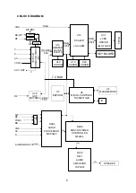
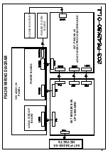
* X driving board
: to produce and provide driving signal for X electrode according to the time
sequence signal sent from logic board.
* Y driving board
: to produce and provide driving signal for Y electrode according to the time
sequence signal sent from logic board.
*Logic board:
to process the image signal sent from the main board, to produce addressing
signal and to provide driving signal for X and Y driving boards.
*Logic BUFFER board (E, F):
To convert the data signal and control signal sent from the logic
board into the signals required by COF
*
Y BUFFER board
(
Upper
,
Lower
)
:
to transmit the scanning signal from the Y driving board to
the screen, which is divided into upper and lower parts.
*
COF:
to convert the signal sent from the logic BUFFER board into the address signal used by
the screen.
II. Trouble
diagnosis:
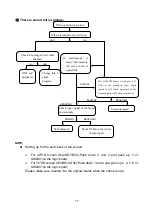
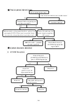
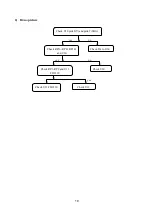
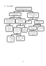
1. The screen is not bright:
a. Check to see if the power supply plug from the power filter board to the power supply board is
well inserted into the socket. If not, plug it in.
b. Check if the fuse on the power supply board is blown up. If yes, replace it for a good one.
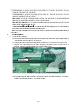
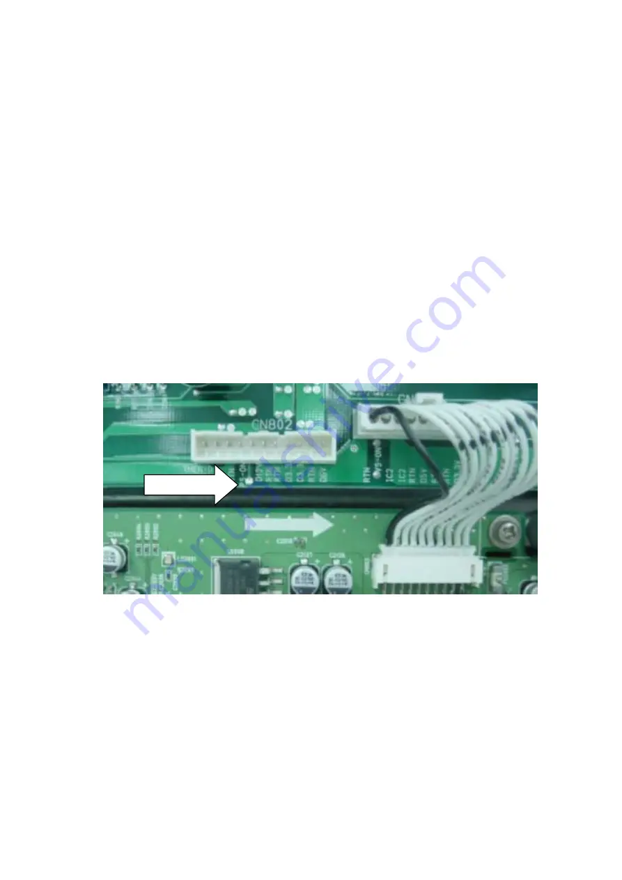
c. Remove our main board and the video frequency processing board, ground the pin 4
POWER_ON/OFF of socket CN802 of the power supply board,
and then push the slide switch SW2001 on the logic board to the internal modes (1, 3 up and 2,
4 down) from external modes (1, 2, 4 up and 3down)
Weld drop
Содержание PS42K8
Страница 1: ...COLOR TELEVISION PS42K8...
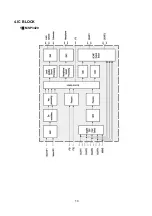
Страница 11: ...10 4 IC BLOCK 1 MSP3420...
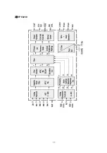
Страница 12: ...11 2 VPC3230...
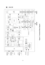
Страница 13: ...12 3 JAG ASM...
Страница 27: ......
Страница 28: ......
Страница 29: ......
Страница 30: ......
Страница 31: ......
Страница 32: ......
Страница 33: ......
Страница 34: ......
Страница 35: ......
Страница 36: ......
Страница 37: ......
Страница 38: ......
Страница 39: ......
Страница 40: ......
Страница 41: ......

