


xCORE-200 Clock Frequency Control
I N T H I S D O C U M E N T
·
PLL and Clock Divider Overview
·
·
·
Configuring the xCORE-200 Device
·
·
·
Example System Clock Divider Configurations
·
Configuring the Clock System Through the XN File
·
1
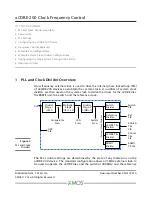
PLL and Clock Divider Overview
A low frequency external clock is used to drive the internal phase locked loop (PLL)
of xCORE-200 devices and obtain the system clock. A number of system clock
dividers are then used on the system clock to derive the clocks for the xCORE tiles,
the RGMII unit, the switch and the reference clock.
XCore0
Tile
Clk
XCore1
Tile
Clk
Divider
Stage 1
÷(R+1)
CLK
Multiplier
Stage
*((F+1)÷2)
Divider
Stage 2
÷(OD+1)
Switch
Divider
System
Clock Div
iders
Reference
Divider
xCORE Tile
Divider
Switch
Clk
Ref
Clk
Comparator
Freq
VCO
Freq
System
Freq
xCORE Tile
Divider
RGMII
Divider
RGMII
TX Clk
USB
Clk
Figure 1:
PLL and Clock
Dividers
The PLL’s initial settings are determined by the state of any mode pins on the
xCORE-200 device. The standard configuration allows a 25MHz external clock to
be used to operate the xCORE tiles and the switch at 400MHz, and the reference
Publication Date: 2016/10/3
Document Number: XM010761A
XMOS © 2016, All Rights Reserved


