background image

7. From the 20x4 box, remove the Y-Arm assembly and the included 

hardware bag (includes M2, M3, and M5 allen keys, 1 M5x25 screw, and 2 
M5x15 screws). NOTE: Remove the Y-Arm by grabbing it from the middle. 
Carefully set it on the side. 


a. Also remove any additional accessories you may have ordered. 


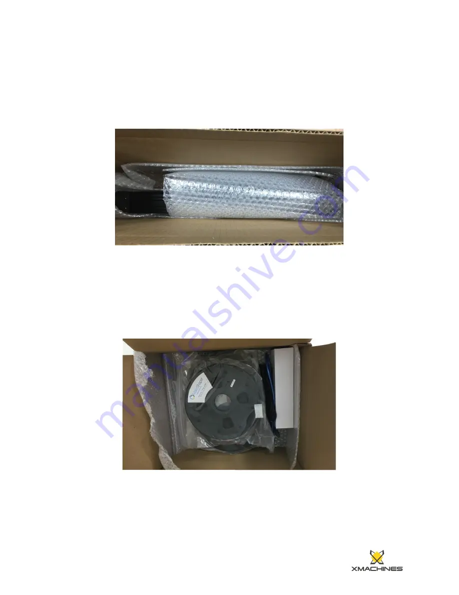
8. From the 15x12 box, remove the power supply, cables (2 cables), filament, 

print bed and any other accessories included. 


Next: Move onto Setting Up Your Lorei! 


Содержание Lorei

Страница 1: ...xt to a flat and clear work surface Before unpacking make sure the printer is oriented with the top side up The bottom of the box is the side with the printed dimensions on it 2 Carefully remove the 20x4 and 15x12 cardboard boxes 3 Remove the top foam from the printer tower ...

Страница 2: ...h foam out of the box and set it on a flat and clear work surface 5 Remove the foam from the back of the printer while securely grasping the printer from the sheet metal at the top of the tower 6 While still holding the top of the tower remove the front piece of foam ...

Страница 3: ...crew and 2 M5x15 screws NOTE Remove the Y Arm by grabbing it from the middle Carefully set it on the side a Also remove any additional accessories you may have ordered 8 From the 15x12 box remove the power supply cables 2 cables filament print bed and any other accessories included Next Move onto Setting Up Your Lorei ...

Страница 4: ...Setting Up Your Lorei 1 Attach the Y Arm to the printer a Detach the acrylic cover from the housing of the printer by taking off the M3 screws using the M3 2 5 mm allen key provided ...

Страница 5: ...b Carefully set the printer on its side c Orient the Y Arm relative to the main frame of the body following the image shown below ...

Страница 6: ... aligned slot the Y Arm into the rubber stop ends and press it towards the housing while keeping the holes aligned Keep the Y Arm pressed towards the housing and use the M5x25 long screw and provided M5 allen key to fasten the Y Arm to the L cut extrusion on the main frame ...

Страница 7: ...Note Be careful not to fasten the screw in too far as this may damage the threading ...

Страница 8: ...e Use the M5x15 screws x2 on the bottom of the housing to finish mounting the Y Arm to the main frame ...

Страница 9: ...Endstop into the controller board i The Y Motor wire and Y Endstop come attached to the Y Arm assembly ii The Y Motor wire attaches to the port labeled Y iii The Y Endstop attaches to the port labeled Y g Re attach the acrylic cover ...

Страница 10: ...e image Slide one side of the bed into two of the bed clips and then push down on the other side to secure the bed Note that the distances from the clips to the sides of the bed are different The longer one should be farther away from the printer i Be sure that the cut outs on the edges of the bed and the nubs in the bed clips are fit together ...

Страница 11: ...e them using the four metal clips Place the clips at the edge of the bed so that two are facing away from the printer and two are facing towards the tower of the printer i Also note that the larger side of the clips should be on the metal not the glass ...

Страница 12: ...y to an outlet until the instructions have been followed thoroughly c Lift Plastic Protector to access the connection points d In order to attach the cables to the power supply use a screwdriver to loosen the screw on the terminal enough to slide in the corresponding connector Push the corresponding wire terminal into the slot as far as it will go While holding it in place tighten the screw back d...

Страница 13: ...onnect DC printer plug by connecting Blue to Positive V and Black to Negative V There are multiple V and V connections It does not matter which one is used for making the connections as long as Blue is to V and Black is to Negative V g Once wired ensure the plastic flap is down before connecting to power Leave the flap down and never come in contact with the connections ...

Страница 14: ... Connect to power and insert the plug into the back side of the printer with the flat end facing up i Flip the switch on the back of the printer to the ON position j LCD will show display when powered on ...

Страница 15: ...4 Calibrate the Z offset a From the home screen press in the click wheel b Navigate to Control and press in c Navigate to Motion and press in d Navigate to Z Offset and press in ...

Страница 16: ...fset Moving the wheel counterclockwise negative on the LCD will bring the print heads closer to the bed while clockwise positive on the LCD will move the print heads away from the bed f Navigate to Control and press in ...

Страница 17: ... mm until a successful first layer is achieved Z Offset adjustment can only be seen through running a print i Offsets are not cumulative This means that if an offset of 2 is too far then the next offset should be 4 to get the print head closer i These example layers are each at a difference of 2 mm Greater or lower adjustments can be made as needed ...

Страница 18: ...e bed may not be perfectly level so it can be adjusted using the screws at the bottom of the bed clips and the provided 3M allen key b Turn the screws to lift the bed at each of the corners of as needed until the bed is level ...

Страница 19: ......

Отзывы: