


60
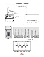
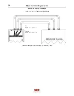
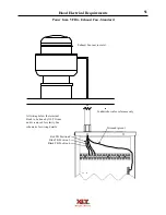
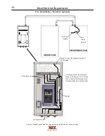
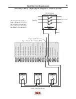
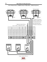
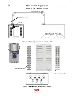
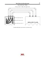
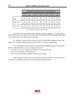
Hood Electrical Requirements
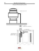
A1
A2
MUA Unit Relay
Power In
Power Out
Supply from
breaker panel
(up to 10 Amps
Determined by
MUA)
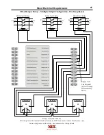
MUA Damper Relays - Single Output Configuration - World (optional)
Relays located in VFD box
R4
R3
R2
All wiring below the terminal block to be done by XLT Ovens and is shown for reference only.
Some wiring removed for clarity. See schematic for wiring details.
Содержание 1832-AE-B
Страница 43: ...43 This page intentionally left blank ...
Страница 88: ...This page intentionally left blank ...
Страница 95: ...95 Oven Schematic 1832 2440 3240 3255 3855 Square Burner Standard ...
Страница 96: ...96 Oven Schematic 1832 2440 3240 3255 3855 Square Burner World ...
Страница 97: ...97 Oven Schematic 1832 2440 3240 3255 3855 Round Burner Australia ...
Страница 98: ...98 Oven Schematic 3270 3870 Square Burner Standard RH Control Box ...
Страница 99: ...99 3270 3870 Square Burner Standard LH Control Box Oven Schematic ...
Страница 100: ...100 Oven Schematic 3270 3870 Square Burner World RH Control Box ...
Страница 101: ...101 Oven Schematic 3270 3870 Square Burner World LH Control Box ...
Страница 102: ...102 3270 3870 Round Burner Australia LH Control Box Oven Schematic ...
Страница 103: ...103 Oven Schematic 3270 3870 Round Burner Australia RH Control Box ...
Страница 104: ...104 Hood Schematic Standard ...
Страница 105: ...105 Hood Schematic World ...
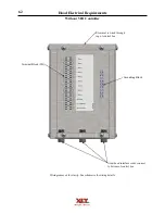
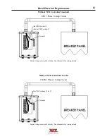
Страница 106: ...106 Hood Schematic Without VFD Controller ...


