STEP 2
IIIIIIIIIIIIIIIIIIIIIIIIIIIIIIIIIIIIIIIIIIIIIIIIIIIIIIIIIIIIIIIIIIIIII
STEP 6
IIIIIIIIIIIIIIIIIIIIIIIIIIIIIIIIIIIIIIIIIIIIIIIIIIIIIIIIIIIIIIIIIIIIII
STEP 4
IIIIIIIIIIIIIIIIIIIIIIIIIIIIIIIIIIIIIIIIIIIIIIIIIIIIIIIIIIIIIIIIIIIIII
STEP 8
IIIIIIIIIIIIIIIIIIIIIIIIIIIIIIIIIIIIIIIIIIIIIIIIIIIIIIIIIIIIIIIIIIIIII
Connect the Power Connector
A. Turn the PC system OFF.
B. Connect the PC systems’ 12V ATX power supply’s available 4-pin
disk drive-type power connector to the board (J25).
Warning: Using any other power supply connector other than the
4-pin in-line connector, will result in damage to the PC system
and the ML605 board.
C. The power switch Sw2 should be switched to the ON position
(away from the bracket edge).
Performance Monitor Application: Verify Board Status
Click on the
System Status
tab to confirm board status and PCIe
settings:
A. Link Status: Up
B. Link Speed: 5.0Gbps
C. Link width: x4
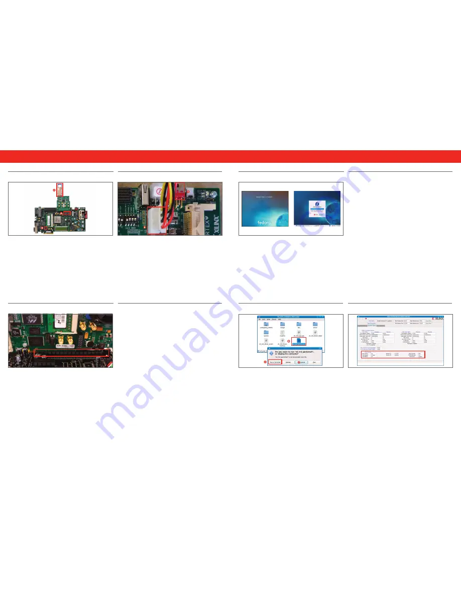
Load Driver and Launch Performance Monitor application
A. Navigate to the
v6_pcie_10Gdma_ddr3_xaui
folder.
B. Double-click
v6_trd_quick_start
. This will build kernel objects,
insert driver modules and launch the Performance Monitor
Application GUI.
C. Click
Run in Terminal
to proceed.
Copy Contents of USB Flash Drive
A. The reference design files are provided on the USB flash drive
delivered with the kit.
B. Insert the USB flash drive into a USB connector of the PC system.
C. wait for the Fedora 10 OS to mount the USB flash. when the flash
is mounted, an icon pops up on the desktop.
D. Double-click on the USB flash drive icon and copy the
v6_
pcie_10Gdma_ddr3_xaui
folder into the live user’s home folder/
directory.
E. To unmount the USB flash, right-click on the USB flash drive icon
and select Unmount Volume.
Boot PC from CD-ROM
A. Configure the PC system to boot from the CD-ROM drive.
B. Place the Fedora 10 Live CD into the CD-ROM drive.
For further information, please refer to the Virtex-6 FPGA Connectivity
Kit Getting Started Guide for more details.
VIRTEX-6 FPGA CONNECTIVITY KIT
VIRTEX-6 FPGA CONNECTIVITY KIT
HARDwARE SETUP GUIDE
HARDwARE SETUP GUIDE
STEP 1
IIIIIIIIIIIIIIIIIIIIIIIIIIIIIIIIIIIIIIIIIIIIIIIIIIIIIIIIIIIIIIIIIIIIIII
STEP 5
IIIIIIIIIIIIIIIIIIIIIIIIIIIIIIIIIIIIIIIIIIIIIIIIIIIIIIIIIIIIIIIIIIIIIII
STEP 3
IIIIIIIIIIIIIIIIIIIIIIIIIIIIIIIIIIIIIIIIIIIIIIIIIIIIIIIIIIIIIIIIIIIIIII
STEP 7
IIIIIIIIIIIIIIIIIIIIIIIIIIIIIIIIIIIIIIIIIIIIIIIIIIIIIIIIIIIIIIIIIIIIII
Board Setup and Configuration
The ML605 is shipped with the FMC Connectivity Daughter Card
module attached to the FMC_HPC connector. To run the demonstration,
you will need to externally loopback the XAUI data using a CX4
loopback connector provided in the kit.
A. Ensure correct Switch Settings:
• S1: 1-OFF, 2-OFF, 3-OFF, 4-ON
• S2: 1-ON, 2-OFF, 3-OFF, 4-ON, 5-ON, 6-OFF
B. Ensure Jumper J42 block: pins3-4 are shorted
C. Plug in the CX4 loopback connector:
• Plug the CX4 loopback connector on the FMC Connectivity
Daughter card’s J2 connector.
Boot Fedora 10 Live and Automatically Login
A. The screens above will appear on Power UP.
B. wait two to three minutes depending on the system configuration
for the PC to boot completely.
Insert ML605 Board into PCIe Express Slot
A. Identify the x8 / x16 PCIe Express slot on the PC motherboard.
B. Insert the ML605 board into the PCI Express slot through the PCIe
x8 edge connector.
C. Turn the power ON. The PCIe 10GDMA DDR3 XAUI targeted
reference design will be loaded from the Platform Flash.


