


SP605 Hardware User Guide
www.xilinx.com
25
UG526 (v1.1.1) February 1, 2010
Detailed Description
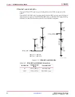
SMA Connectors (Differential)
A high-precision clock signal can be provided to the FPGA using differential clock signals
through the onboard 50-ohm SMA connectors J38 (N) and J41 (P).
8
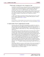
. Multi-Gigabit Transceivers (GTP MGTs)
The SP605 provides access to 4 MGTs.
•
One (1) MGT is wired to the PCIe x1 Endpoint (P4) edge connector fingers
•
One (1) MGT is wired to the FMC LPC connector (J2)
•
One (1) MGT is wired to MGT SMA connectors (J36, J37)
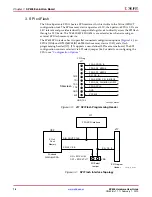
•
One (1) MGT is wired to the SFP Module connector (P4)
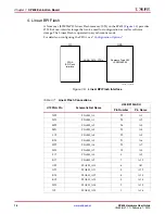
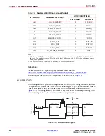
The SP605 includes a set of six SMA connectors for the GTP (MGT) RX/TX Port and GTP
(MGT) Clock as described in
Figure 1-10
and
Table 1-10
.
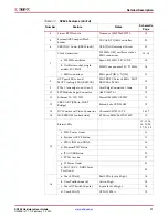
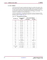
Table 1-9:
SP605 Clock Source Connections
Source
U1 FPGA Pin
Schematic Net Name
Pin
Number
Pin Name
U6 200MHZ OSC
K22
SYSCLK_N
5
OUT_B
K21
SYSCLK_P
4
OUT
X2 27MHZ OSC
AB13
USER_CLOCK
5
OUT
USER_SMA_CLOCK
M19
USER_SMA_CLOCK_N
J38.1
–
SMA Connectors
M20
USER_SMA_CLOCK_P
J41.1
–


