


14
SP305 Spartan-3 Development Platform User Guide
www.xilinx.com
UG216 (v1.1) March 3, 2006
SP305 Spartan-3 Development Platform User Guide
R
Table 2-9
summarizes the Error LED definitions and connections
Reference
Designator
Label/Definition
Color
FPGA Pin
Error 1
Error 2
.
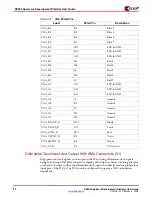
RS-232 Serial Port 1 (20)
The SP-305 board contains two male DB-9 RS-232 serial port to enable the FPGA to
communicate with serial data devices. Because the serial port #1 is wired as a host (DCE)
device, a null modem cable is normally required to connect the board to the serial port on
a PC. The serial port is designed to operate up to 115200 Bd. An interface chip is used to
shift the voltage level between FPGA and RS-232 signals.
Label
FPGA Pin
Description
UART_SOUT
AA11
DB9- P3
UART_SIN
Y11
DB9- P3
Note:
Because the FPGA is only connected to the TX and RX data pins on the serial port, other RS-
232 signals, including hardware flow control signals, are not utilized. Flow control should be disabled
when communicating with a PC.
RS-232 Serial Port 2 (21)
A secondary serial interface is available on the USB chip. By using header J32 and J33 the
TX and RX can be selected between the USB debug port on the USB controller chip or the
Second FPGA UART port. The USB debug port is selected by moving the jumper on J32
and J33 to the Pin 1,2 setting. The second FPGA UART RX and TX are selected by moving
the jumper on J32 and J33 to the Pin 2,3 setting.
Because the serial port is wired as a host (DCE) device, a null modem cable is normally
required to connect the board to the serial port on a PC. The serial port is designed to
operate up to 115200 Bd. An interface chip is used to shift the voltage level between FPGA
and RS-232 signals.
Label
FPGA Pin
Description
UART1_SOUT
AC8
DB9- P1 -- J32 bottom (2,3)
UART1_SIN
AB8
DB9- P1-- J33 bottom (2,3)
Note:
Because the FPGA is only connected to the TX and RX data pins on the serial port, other RS-
232 signals, including hardware flow control signals, are not utilized. Flow control should be disabled
when communicating with a PC.
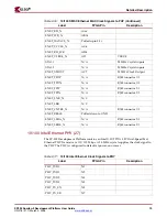
Table 2-9:
User and Error LED Connections
DS205
Red
AB11
DS206
Red
F12
Table 2-10:
RS232 FPGA Pin Connections
Table 2-11:
RS232 FPGA Pin Connections


