


8
SP305 Spartan-3 Development Platform User Guide
www.xilinx.com
UG216 (v1.1) March 3, 2006
SP305 Spartan-3 Development Platform User Guide
R
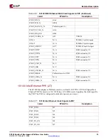
I/O Voltage Rails
The FPGA has 7 banks. The I/O voltage applied to each bank is summarized in
Table 2-1
.
FPGA Bank
I/O Voltage Rail
3.3V
2.5V
2.5V
User selectable as 2.5V or 3.3V using jumper J29
3.3V
3.3V
3.3V
2.5V
AC Adapter and Input Power Switch/Jack (2)
The SP-305 board ships with a 15W (5V @ 3A) AC adapter. The power connector is a 2.1mm
x 5.5mm barrel type plug (center positive). For applications requiring additional power,
such as the use of expansion cards drawing significant power, a larger AC adapter may be
required. If a different AC adapter is used, its load regulation should be less than 10% or
better than +/- 10%. The power switch turns the board on and off by controlling the supply
of 5V to the board.
Power Indicator LED (3)
The PWR Good LED lights when the 1.2V, 2.5V, and 3.3V power supplies are all at their
nominal operating conditions. If the PWR Good LED is off, blinking, or glowing lightly, a
fault condition, such as a short or overload condition, may exist.
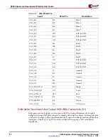
On-board Power Supplies (4)
Power supply circuitry on the board generates 1.2V, 1.25V, 1.8V, 2.5V, and 3.3V voltages to
power the components on the board. The 1.2V, 2.5V, and 3.3V supplies are driven by
switching power regulators. When these three switching regulators report they are
running at their nominal voltages, the PWR Good LED is turned on.
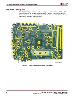
The diagram in
Figure 2-4
shows the power supply architecture and maximum current
handling on each supply. Note that the typical operating currents are significantly below
Table 2-1:
I/O Voltage Rail of FPGA Banks
0
1
2
3
4
5
6
7


