Chapter 6: Example Design
DPU IP Product Guide
37
PG338 (v1.2) March 26, 2019
ZCU102 Board Configuration
1.
Connect the Micro USB cable into the ZCU102 Board Micro USB UART (J83) and the other end into
an open USB port on the host PC. This cable is used for UART over USB communication.
2.
Insert the SD card with the content of image folder into the SD card slot.
3.
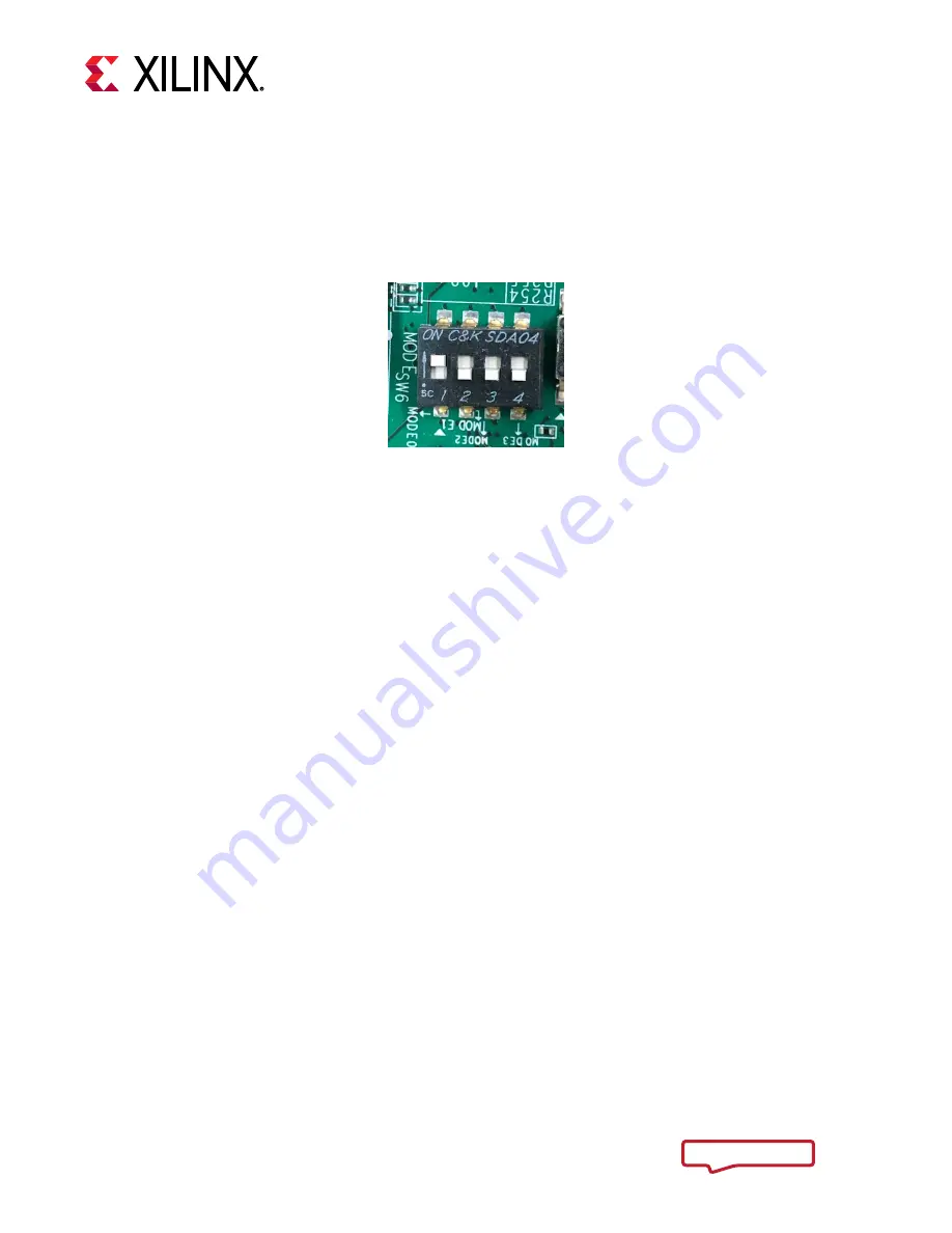
Set the SW6 switches and configure the boot setting to boot from SD as shown here.
Figure 28: Boot from SD
4.
Connect 12V power to the ZCU102 6-Pin Molex connector.
5.
Switch on SW1 to power on the ZCU102 board.
Project Build Flow
This section is about how to build the reference Vivado project with Vivado 2018.2. For information
about setting up your Vivado environment, refer to the
Vivado Design Suite User Guide
).
Building the hardware design consists of the following steps:
Building the Hardware Design on Linux
1.
Open a Linux terminal.
2.
Change the directory to
$TRD_HOME/pl
.
3.
Create the Vivado IP integrator project and invoke the GUI by running the following command:
% vivado -source scripts/trd_prj.tcl
Building the Hardware Design on Windows
1.
Select
Start > All Programs > Xilinx Design Tools > Vivado 2018.2 > Vivado 2018.2
.
2.
On the Quick Start screen, click
Tcl Console
.
3.
Type the following command in the Tcl console:
cd $TRD_HOME/pl
source scripts/trd_prj.tcl
After running the scripts, the Vivado IP integrator block design appears as shown in the following
figure.


