General Procedures and Information
FaxCentre 2121/2121L
11/06
6-15
Connections
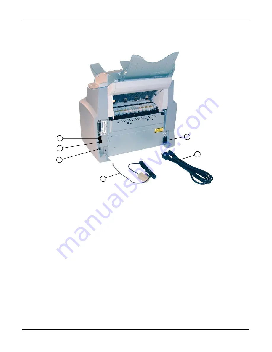
Figure 2
Connecting the telephone line and LAN
•
Plug one end of the telephone lead (1) into socket (A) of the machine and the other end into
the telephone wall socket (the types of connector may vary depending on the country).
•
If the machine is equipped with a LAN connection (depending on the model), plug one end of
the LAN cable (supplied by your network administrator) into socket (B) of the machine and
the other end into the local area network socket allocated to your fax.
Powering up the machine
WARNING
:
Refer to the safety regulations in the Introduction
•
Plug one end of the power cord (2) into the power socket (D) of the machine and the other
end into the wall socket (the types of connector may vary depending on the country).
•
Set the on/off switch to the <I> position (On). After a few seconds, as soon as the warm-up of
the machine is finished, the date and the time are displayed.
C
B
A
D
2
1
Содержание 2121L - FaxCentre B/W Laser
Страница 1: ...708P88662 11 06 Service Manual 708P88662 FaxCentre 2121 2121L ...
Страница 20: ...Service Call Procedures 1 2 11 06 FaxCentre 2121 2121L Page intentionally blank ...
Страница 28: ...Status Indicator RAPs 2 2 11 06 FaxCentre 2121 2121L Page intentionally blank ...
Страница 44: ...Image Quality 3 2 11 06 FaxCentre 2121 2121L Page intentionally blank ...
Страница 56: ...Repairs Adjustments 4 2 11 06 FaxCentre 2121 2121L Page intentionally blank ...
Страница 106: ...Spare Parts List 5 2 11 06 FaxCentre 2121 2121L PL 1 FaxCentre 2121 Assemblies and Trays 3 2 1 4 7 6 5 9 8 10 ...
Страница 108: ...Spare Parts List 5 4 11 06 FaxCentre 2121 2121L PL 2 Machine Assembly 1 3 5 6 2 4 ...
Страница 110: ...Spare Parts List 5 6 11 06 FaxCentre 2121 2121L PL 3 Control Panel and Scanner 2 1 ...
Страница 112: ...Spare Parts List 5 8 11 06 FaxCentre 2121 2121L PL 4 Retard Pad and White Roller Assemblies 1 5 6 7 4 3 2 8 ...
Страница 114: ...Spare Parts List 5 10 11 06 FaxCentre 2121 2121L PL 5 Printer Unit Assembly 1 4 2 3 8 5 6 7 9 11 10 ...
Страница 116: ...Spare Parts List 5 12 11 06 FaxCentre 2121 2121L PL 6 Control Panel Assembly 1 2 3 4 5 6 7 8 ...
Страница 118: ...Spare Parts List 5 14 11 06 FaxCentre 2121 2121L PL 7 Paper Tray 1 2 ...
Страница 120: ...Spare Parts List 5 16 11 06 FaxCentre 2121 2121L PL 8 CIS Support and Motor Drive Assemblies 1 2 4 5 3 ...
Страница 122: ...Spare Parts List 5 18 11 06 FaxCentre 2121 2121L PL 9 Drive Transfer Unit ...
Страница 124: ...Spare Parts List 5 20 11 06 FaxCentre 2121 2121L PL 10 Fuser Assembly 2 1 ...
Страница 126: ...Spare Parts List 5 22 11 06 FaxCentre 2121 2121L PL 11 Power Supplies and ROS Unit ...
Страница 128: ...Spare Parts List 5 24 11 06 FaxCentre 2121 2121L PL 12 Paper Feed Section ...
Страница 130: ...Spare Parts List 5 26 11 06 FaxCentre 2121 2121L PL 13 Consumables Tools and Kits ...
Страница 132: ...Spare Parts List 5 28 11 06 FaxCentre 2121 2121L Page intentionally blank ...
Страница 134: ...General Procedures and Information 6 2 11 06 FaxCentre 2121 2121L Page intentionally blank ...
Страница 187: ...General Procedures and Information FaxCentre 2121 2121L 11 06 6 55 Figure 1 ...
Страница 206: ...General Procedures and Information 6 74 11 06 FaxCentre 2121 2121L GP 23 Service Log ...
Страница 208: ...Wiring Diagrams 7 2 11 06 FaxCentre 2121 2121L Page intentionally blank ...
Страница 219: ...Wiring Diagrams FaxCentre 2121 2121L 11 06 7 13 Main PBA and CPU PJ Locations Figure 1 ...
Страница 220: ...Wiring Diagrams 7 14 11 06 FaxCentre 2121 2121L WD 1 Connection Diagram 1 of 5 Figure 1 ...
Страница 221: ...Wiring Diagrams FaxCentre 2121 2121L 11 06 7 15 WD 2 Connection Diagram 2 of 5 Figure 1 ...
Страница 222: ...Wiring Diagrams 7 16 11 06 FaxCentre 2121 2121L WD 3 Connection Diagram 3 of 5 Figure 1 ...
Страница 223: ...Wiring Diagrams FaxCentre 2121 2121L 11 06 7 17 WD 4 Connection Diagram 4 of 5 Figure 1 ...
Страница 224: ...Wiring Diagrams 7 18 11 06 FaxCentre 2121 2121L WD 5 Connection Diagram 5 of 5 Figure 1 ...


