background image

11

Electrode Size

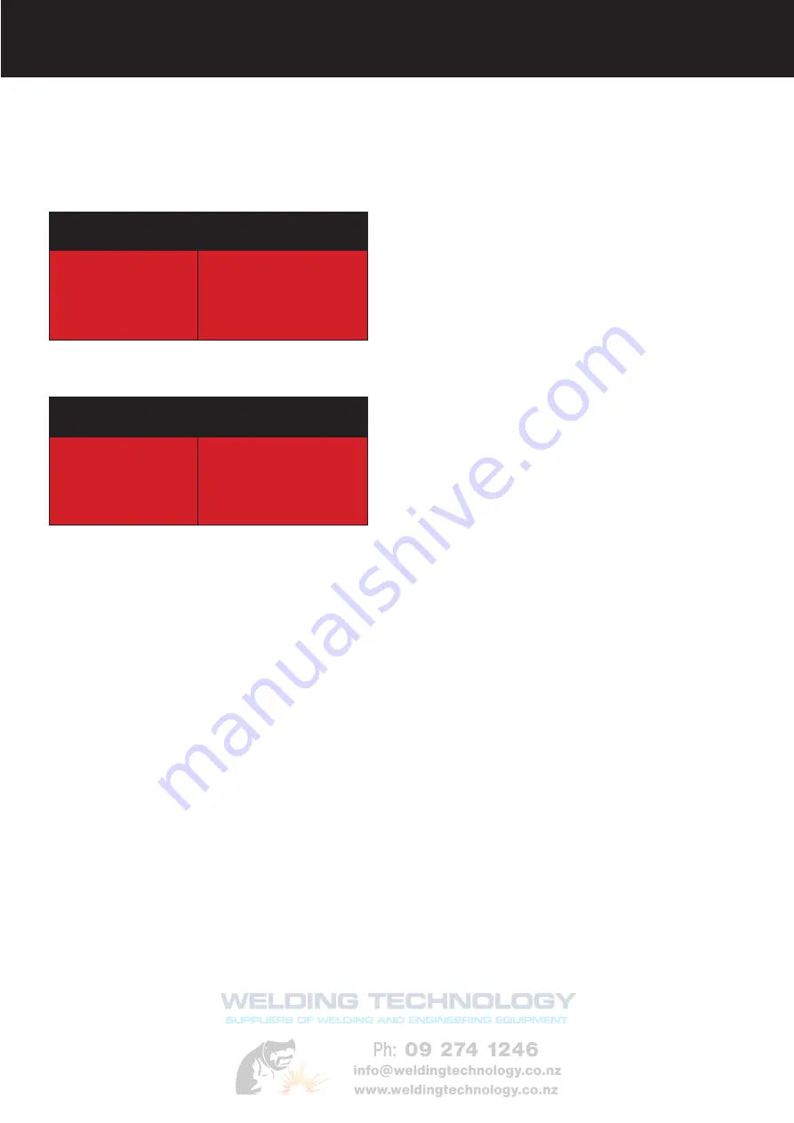
  Average Thickness  Maximum Recommended  


of Material 

Electrode Diameter


1.0 - 2.0mm 

2.5mm 


2.0 - 5.0mm 

3.2mm 


5.0 - 8.0mm 

4.0mm 


8.0 -  > mm 

5.0mm 

The size of the electrode generally depends on the 

thickness of the section being welded, and the thicker 

the section the larger the electrode required. The table 

gives the maximum size of electrodes that maybe used 

for various thicknesses of section base on using a gen-

eral purpose type 6013 electrode.

Correct current selection for a particular job is an im-

portant factor in arc welding. With the current set too 

low, difficulty is experienced in striking and maintaining 

a stable arc. The electrode tends to stick to the work, 

penetration is poor and beads with a distinct rounded 

profile will be deposited. Too high current is accompa

-

nied by overheating of the electrode resulting undercut 

and burning through of the base metal and producing 

excessive spatter. Normal current for a particular job may be considered as the maximum, which can be 

used without burning through the work, over-heating the electrode or producing a rough spattered surface.

The table shows current ranges generally recommended for a general purpose type 6013 electrode. 


Arc Length

To strike the arc, the electrode should be gently scraped on the work until the arc is established. There is a 

simple rule for the proper arc length; it should be the shortest arc that gives a good surface to the weld. An 

arc too long reduces penetration, produces spatter and gives a rough surface finish to the weld. An exces

-

sively short arc will cause sticking of the electrode and result in poor quality welds. General rule of thumb 

for down hand welding is to have an arc length no greater than the diameter of the core wire. 

Electrode Angle

The angle that the electrode makes with the work is important to ensure a smooth, even transfer of metal. 

When welding in down hand, fillet, horizontal or overhead the angle of the electrode is generally between 5 

and 15 degrees towards the direction of travel.  When vertical up welding the angle of the electrode should 

be between 80 and 90 degrees to the work piece. 


Travel Speed

The electrode should be moved along in the direction of the joint being welded at a speed that will give the 

size of run required. At the same time, the electrode is fed downwards to keep the correct arc length at all 

times. Excessive travel speeds lead to poor fusion, lack of penetration etc, while too slow a rate of travel 

will frequently lead to arc instability,slag inclusions and poor mechanical properties. 


Material and Joint Preparation

The material to be welded should be clean and free of any moisture, paint, oil, grease, mill scale, rust or 

any other material that will hinder the arc and contaminate the weld material. Joint preparation will depend 

on the method used include sawing, punching, shearing, machining, flame cutting and others.  In all cases 

edges should be clean and free of  any contaminates. The type of joint will be determined by the chosen 

application.

Welding Current (Amperage)


Electrode Size 

Current Range  


ø mm 

(Amps)


2.5mm 

60 - 95 


3.2mm 

100 - 130 


4.0mm 

130 - 165 


5.0mm 

165 - 260 

Electrode Selection

As a general rule, the selection of an electrode is straight forward,in that it is only a matter of selecting an 

electrode of similar composition to the parent metal. However, for some metals there is a choice of several 

electrodes, each of which has particular properties to suit specific classes of work. It is recommend to con

-

sult your welding supplier for the correct selection of electrode.

MMA (Stick) Welding Fundamentals

Содержание Viper ARC140V

Страница 1: ...1 Please read and understand this instruction manual carefully before the installation and operation of this equipment ARC140V ARC160V DC INVERTER WELDERS OPERATORS MANUAL...

Страница 2: ...erformance and interface between man and machine should be Within our team are specialist welders that have a proven history of welding knowledge and exper tise giving vital input towards ensuring tha...

Страница 3: ...rotected from hot metal and sparks Frequently inspect input power cable for wear and tear replace the cable immediately if damaged bare wiring is dangerous and can kill Do not use damaged under sized...

Страница 4: ...explode Because gas cylinders are normally part of the welding process be sure to treat them carefully CYLINDERS can explode if damaged Protect gas cylinders from excessive heat mechanical shocks phy...

Страница 5: ...rking to bring down the temperature inside the equipment The machine will be ready for use again when the internal temperature reaches safe level 2 3 Over Voltage Supply Regarding the power supply vol...

Страница 6: ...ith DC Scratch Start Tig capability and connection of the XA17V Tig torch allows DC Tig welding of steel stainless steel bronze and copper The VIPER 140 is an exceptional machine for the price and is...

Страница 7: ...ydrogen The VIPER160 is also equipped with DC Scratch Start Tig capability and connection of the XA17V Tig torch allows DC Tig welding of steel stainless steel bronze and copper The VIPER160 is an exc...

Страница 8: ...ol Dial Negative Output Terminal Positive Output Terminal Primary Power LED Thermal Alarm LED Primary Input Power Lead On Off Power Switch Rear Machine Layout Description Front Machine Layout Descript...

Страница 9: ...work to create the arc and hold the electrode steady to maintain the arc 6 Hold the electrode slightly above the work piece to maintain the arc while travelling at an even speed to create and even we...

Страница 10: ...ross the arc into the molten pool and becomes the deposited weld metal The deposit is covered and protected by a slag which comes from the electrode coating The arc and the immediate area are envelope...

Страница 11: ...length no greater than the diameter of the core wire Electrode Angle The angle that the electrode makes with the work is important to ensure a smooth even transfer of metal When welding in down hand...

Страница 12: ...it 4 Connect the gas line of the Tig torch to regulator and connect the regulator to the gas cylinder 5 Assemble front end parts of the TIG torch fitting a sharpened tungsten suitable for DC welding...

Страница 13: ...ards lightly touch the tungsten to the work piece as you drag the torch 9 The arc will strike as it does lift the tungsten slightly from the work piece to maintain the arc 5 Assemble front end parts o...

Страница 14: ...ypes DC TIG welding is also the cleanest weld with no sparks or spatter LIFT ARC IGNITION for TIG tungsten inert gas Welding Lift Arc is a form of arc ignition where the machines has low voltage on th...

Страница 15: ...pool Travel direction Angle torch Add Tig filler wire Retract the filler wire Move the torch forward to the front of the weld pool Repeat the process gas shield TIG Welding Fusion Technique Manual TIG...

Страница 16: ...nergy output E3 Tungsten Electrodes run cooler than 2 thoriated tungsten thereby extending overall tip lifetime E3 Tungsten Electrodes work well on AC or DC They can be used DC electrode positive or n...

Страница 17: ...running lengthwise and thus grinding crosswise is grinding against the grain If electrodes are ground crosswise the electrons have to jump across the grinding marks and the arc can start before the t...

Страница 18: ...ilable in 4m 8m Lengths Spare Parts Part Number Description 10 ERJK100 Jointing Repair Kit 11 ERNCS 32 Neoprene Cover x 3 2m ERNCS 72 Neoprene Cover x 7 2m 12 ERCO100 40 Sheath x 4m c w Leather Cover...

Страница 19: ...ody 1 6mm 45V26 Gas Lens Collet Body 2 4mm 45V27 Gas Lens Collet Body 3 2mm Part Description 54N18 Gas Lens Nozzle 6mm 4 54N17 Gas Lens Nozzle 8mm 5 54N16 Gas Lens Nozzle 10mm 6 54N15 Gas Lens Nozzle...

Страница 20: ...larger electrode Poor welding technique Use the correct welding technique or seek assistance for the correct technique Poor joint preparation Check the joint design and fit up make sure the material i...

Страница 21: ...etal Remove materials like paint grease oil and dirt including mill scale from base metal Contaminated filler wire Remove all grease oil or moisture from filler metal Incorrect filler wire Check the f...

Страница 22: ...e flow rate on the regulator to approximately 8 10 l min 4 Close the cylinder valve and pay attention to the needle indicator of the contents pressure gauge on the regulator if the needle drops away t...

Страница 23: ...23...

Страница 24: ...24 P O Box 4241 711 Tremaine Avenue Plamerston North New Zealand Tel 64 0 6 355 1103 Fax 64 0 6 357 2161 E Mail esseti esseti co nz New Zealand Limited www xcelarc com...

Отзывы: